Systems Reference Library
IBM 1710 Control System
This manual contains the basic programming and operating information required to control industrial processes with the IBM 1710 Control System. Information concerning industrial processing and instrumentation is presented in the technical language used in these fields.
This manual makes the following publications obsolete:
IBM 1710 Control System Reference Manual (A26-5601-0)
IBM Technical Newsletter N26-0021
IBM Technical Newsletter N26-0036 (
IBM 1710 Additional Special Features and Attached Units (A26-5660-1)
IBM Technical Newsletter N26-0041
Page IBM 1710 Control System. . . .. .~
Applications ... 5
1710 Control System Units... . . . 7
1710 Publications and Programming Systems. . . 7
1711 Data Converter... .... ... .... ... ... ... 8
1712 Multiplexer and Terminal Unit (MTV) , Model I ... 10
1711 Data Converter Features . ... 12
Ana1og-to-Digital Converter (ADC) . . . 12
Real-Time Clock (RTC) . . . 13
Terminal Address Selector (TAS) ... 14
1711 Operator's Panel ... 14
1710 Special Features and Additional Units . ... 15
Standard Terminal Block ... 15
Interrupt/Process Branch Indicator Terminals. . . .. 15
Contact Sense Terminal Block. . . .. 16
Thermocouple Terminal Block ... 16
Measuring Thermocouple Temperatures with the 1710 .... 16
High-Speed Contact Sense ... 18
Contact Operate ... 18
Analog Output. . . .. 19
Controlling Instrumentation ... 20
Closed-Loop Computer Control. . . .. 21
Analog Output Programming ... 23
Analog Output Fail-Safe Features ... 24
Interrupt ... 25
Interrupt Modes of Operation ... 25
External and Internal Interrupts ... 26
Random Addressing of TAS . . . • . • • . . . • . . . .. 28
Process Branch Indicators ... 29
Manual Entry . . . .. 29
1710 Process Operator Units ... 29
General Description ... < • • • • • • • • • • • • • • • • • • • • • • • • • 30 IBM 1713 Manual Entry Unit " . . . .. 31
IBM 1714 Sense Switch Unit ... 32
IBM 1715 Digital Display Unit ... 33
IBM 1717 Output Printer. . . .. 34
Serial Input/Output Channel ... 36
Programming Process Operator Units ... 40
Contents
Page 1710 Instructions . ... 44Selecting Input Signals and Contacts ... 44
Operating Contact Points and Set-Point Positioners ... 48
Interrupt Routine Instructions ... 48
Reading the Contents of TAS and RTC into Core Storage ... 49
Input/Output Operations with the 1710 Process Operator Units ... 50
Branch Instructions ... 50
1711 Operator's Panel ... 54
System Data Flow. . . .. 57
Appendix A ... 59
Instruction Summary ... 59
Appendix B ... 62
Summary of 1710 Features and Units ... 62
Appendix C ... 63
Significance of P and Q Addresses . . . .. 63
Appendix 0 ... 66
IODR Character Code Chart ... 66
Appendix E ... ... 67
Abbreviations and Acronyms ... 67
Table Areas in Core Storage . . . .. 67
Bit Configuration of Decimal Digits ... 67
1620 Storage Register Functions ... 67
Appendix F... . . . .. 68
Multiply and Add Tables ... 68
Appendix G... 69
Character Code Chart ... 69
Preface
Publications for the 1710 Control System have been adapted to the new IBM Systems Reference Library format. This publication contains the most current machine reference information for the 1710, and rep-resents a major revision of information contained in the publication IBM 1710 Refej'ence Manual (Form A26-5601) .
Machine reference information for the 1710 Control
1713
Fl
···
-
... .
....
·
.
.
1714
, _ ~:'. 1715
System is contained in the following publications:
IBM 1620 Centml Pmcessing Unit (Modell) A26-5706
IBM 1620 Input/Output A26-5707
IBM 1620 Special Features A26-5708
IBM 1710 Contml System (This publication) A26-5709
IBM 1311 Disk Storage Drive A26-5650
The IBM 1710 Reference Manual (Form A26-5601) is made obsolete by the publications listed above.
1711
~ --~ 1717
The IBM 1710 Control System is specially designed for controlling processes in such industries as petroleum refining, chemical processing, electric utility, natural gas transmission, and steel production. It is an on-line control system that meets the requirements demanded by industrial processing management by offering versa-tility of operation, reliability, and ease of expansion through modular construction of the System.
Reliability is achieved through the use of solid-state circuitry and a high-speed, self-checking, digital com-puter - the IBM 1620. Flexibility is achieved with the
availability of announced special features and addi-tional units, which offer any degree of control from data logging and analysis to complete closed-loop con-trol. The customer may start with the minimum 1710 System required to satisfy initial control and analysis needs, and selectively add or substitute features and units as control requirements change. Each control op-eration can be financially proven before a move toward more complex control is made. The initial investment is protected because changes in control requirements do not necessitate removal of the installed 1710 System.
Applications
The IBM 1710 is capable of accepting electrical signals, both analog and binary, from such devices as thermo-couples, pressure and temperature transducers, flow meters, analytical instruments, and contacts. It provides electrical on/off and analog control signals for the cus-tomer's controlling devices. Typical applications exist in the area of industrial processing and manufacturing quality control.
Industrial Processing
Industrial processing applications are as wide and varied as are the degrees of control that individual processes may require. All control is based on the col-lection of process data, and the more complex the control, the greater the need for rapid collection of data. Some of the degrees of control that a 1710 Control System may exercise follow in order of complexity:
Data Logging and Conversion. Process data is sent to the 1710 System, converted into digital information, and logged for process operator and management re-view.
IBM 1710 Control System
Data Collection and Analysis. Process data is col-lected by the computer for mathematical analysis. Cur-rent performance figures are compared with those obtained in the past, and the results are printed for process operator and management evaluation.
Data Evaluation and Operator Guidance. Process data is collected, analyzed, and evaluated with respect to previously stored guidance charts. Control instruc-tions are then typed out for the process and control room operator, and messages and log sheets are pro-vided for management review.
Process Study. The computer rapidly collects the process data that is necessary for the development of a model of the process. The model is developed by using a combination of empirical techniques and observing past methods of running the process. When a more complete and more precise description of the process is required, a model is constructed by using such mathe-matical techniques as correlation analysis and regres-sion analysis. The process control program is then tested on the mathematical model prior to its use on the process. Extensive operator guide information is obtained. In addition, the model represents consider-able progress toward closed-loop control.
Process Optimization. An extensive computer con-trol program, based on the model of the process, directs the 1710 System. Process data is continuously collected and analyzed for computation of optimum operating instructions. These instructions are given to the process operator via the computer console typewriter.
Closed-Loop Control. Closed-loop control is the ulti-mate in industrial process control. Process conditions obtainable through instrumentation are continuously monitored by the computer. The instrument readings are analyzed rapidly and simultaneously, and the com-putations initiate controlling signals, which are sent to the devices that control the process.
through controlling instrumentation and to provide continued process operator guidance.
Communication between the control room operator and the process is maintained through the Central Processing Unit (cpu). The console typewriter
pro-r
1
1711 Data Converter
1712 Multiplexer cnd
Terminal Unit
vides log sheets and messages that aid management in evaluating process performance. The speed and reli-ability of the 1710 System enable the operation of in
-dustrial processes at a higher level of performance than heretofore realized.
1713 Manual Entry Unit
1714 Sense Switch Unit
1715 Digital Display Unit
1717 Output Printer
1620 Central Processing Unit
The IBM 1710 Control System is comprised of the IBM
1620 Central Processing Unit, the IBM 1711 Data
Con-verter, and the IBM 1712 Multiplexer and Terminal Unit, Modell. In addition, all 1620 and 1710 special
features and additional units are available. Appendix
B is a chart of the features and units that can be utilized
in the 171O Control System. A system configuration
showing all special features anc! additional units and
their prerequisites is contained in the publication IBM 1710 System Configumtion (Form G26-5693)" All sys
-tem components and special features are modularly
constructed and use solid-state (transistorized) cir
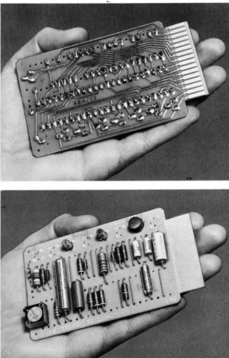
-cuitry. SMS (Standard Modular System) cards (Figure
2) are used throughout the 171O System. These printed
[image:7.618.66.299.338.703.2]circuit cards are pluggable. Each card contains all the
Figure 2. IIlM SMS Card
1710 Control System Units
electronic components and printed wifing for a par
-ticular function or functions. The use of SMS canis not
only makes the system more flexible and reliable, but,
in addition, increases its reliability and availability
be-cause of reduced maintenance requirements.
Abbreviations and acronoyms used in this publi
ca-tion that are peculiar to the 1710 Control System are
listed and defined in Appendix E.
J
7J 0 Publications and Programming SystemsSystems Reference Library
The continuing demands of business and industry have
necessitated the design and manufacture of an incr
eas-ing number and variety of versatile computer systems.
The programmers and operators of these systems (Ire challenged, as never before, to learn and implement
effective man-to-computer communications. The re c-ognition of this challenge and the desire to effect the
highest communication level between all concerned
-manufacturer, system engineer, user, and computer
-has resulted in the establishment of the IBM Systems
Reference Library.
A Systems Reference Library is provided for each computer system. Each reference library includes litera
-ture applicable to the installation and operation of its
respective system. The Systems Reference Library is organized in three main categories:
1. Systems Information - Condensed: introductory and summary publications for machine units and programming systems and a bibliography of all library literature is included in this category. 2. Machine Systems: includes a detailed publication
for each unit and feature of the system and its physical installation (cpu, I/0, Special Features, Physical Planning, etc.) .
3. Programming Systems: includes general and de-tailed publications for each programming system
(SPS, Utility Programs, Processors, etc.) .
1710 Bibliography (Form A26-5695)
Reference literature applicable to the installation and operation of the IBM 1710 Control System is indexed in this bibliography. The bibliography is published in three parts: In Part 1, the publications are listed under major subject headings; this listing can serve as a table of contents for the 1710 Systems Reference Library.
Part 2 is a cross-index of publications by machine type number to help the user find publications for which the title is not known.
Part 3 contains the abstracts of all publications in form number sequence. The abstract of a publication enables the user to determine whether the publication is applicable to his needs.
All 1710 publications listed in this bibliography can be obtained by form number from the local IBM Sales
Representative.
1710 Systems Summary
This publication briefly describes system concepts, sys-tem units, and special features. Of particular impor-tance to the programmer is the section of this manual that describes the programs and programming systems for the 1710 Control System.
17
J J
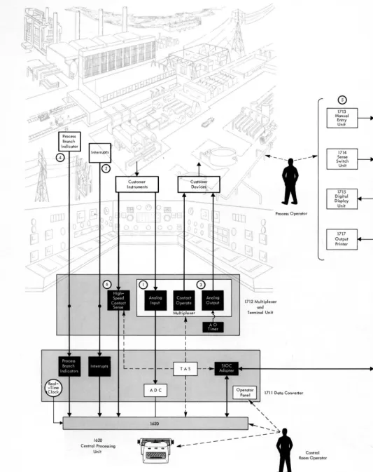
Data ConverterFigure 1 illustrated the relationship between an indus-trial process and the 1710 Control System. The 1711 may be programmed to control processes as follows (the numbers correspond to the circled numbers in Figure 4) :
1. Analog Input signals are sent to the 1710 System via the 1712 MTU. The 1712 is used as the
inter-connecting device between the process and the 1710.
2. The Interrupt feature enables the control system to give prompt attention to critical signals caused by such occurrences as the liquid level of a tank
approaching an overflow condition. The interrupt causes the computer to suspend routine operation, to notify the process operator of the condition, and/or to initiate corrective action. With the in-stallation of special features, corrective action can turn on a motor in the process area which will close a valve and stop liquid flow to the tank.
Interrupts are assigned to high-priority condi-tions in the process that are not expected to occur in normal processing, or if they are expected to occur, their occurrence cannot be scheduled. With-out the ability to interrupt its program at any time7 the computer would repeatedly scan these
signals, even though the signals occur infrequently or not at all.
An internal interrupt, Multiplex Complete, is available when the Input/Output Interrupt fea-ture is installed. The Multiplex Complete inter-rupt is turned on by completion of process input/ output functions such as the end of conversion of an analog input signal. The Multiplex Complete interrupt is used to direct the computer program to a program subroutine that will cause appropri-ate program action such as reading the contents of the ADC register into core storage.
3. Analog Output sends computer-controlled signal pulses to the customer's controlling devices in the process area. Contact Operate is used to turn on or off the customer's process devices (motors, alarms, etc.) .
4. Up to 20 Process Branch Indicators are available for program interrogation of conditions in the process area. Each Process Branch Indicator re-flects the on/off condition of a contact in the process area - if the contact is closed, its associated indicator is on. When the contact opens, the indi-cator is turned off. Thus, as the contacts in the process open and close, their respective indicators in core storage are turned off and on.
Process Branch Indicators can be assigned to signals in the process that are not as critical as those requiring the Interrupt feature, yet must be frequently interrogated by the computer program. These indicators can be individually scheduled for interrogation by the program at timed inter-vals.
(
c
~
1620
Centrol Processing
Unit
~
4---- - - g
• I
[image:9.621.41.574.35.708.2],-~---\
Figure . 4 . Data Flow Diagram of 1710 Control System
Process Operator
1712 Multiplexer and
Terminal Unit
1711 Doto Converter
Control Room Operator
o
1714
Sense Switch
Unit
1717 Output
6. The High-Speed Contact Sense feature enables the
1710 System to sense the on/off condition of up
to 400 contacts in the process. The contacts are
scanned and the status of the contacts is placed
in 1620 core storage at rates of up to 100,000 points
per second.
This feature is used to terminate the majority
of on/off signals in the process that are neither
critical nor must be interrogated individually.
These signals may occur frequently or infr
e-quently, but they are scanned by the computer as
a routine operation.
Unlike Process Branch Indicators that can be
continually turned on and off inside the computer
Figure 5. 1712 Multiplexer and Terminal Unit, Modell
by the opening and closing of their respective
con-tact poi nts in the process, the status of contact sense
points are recorded in the computer's core storage as being either off or on at the particular point in time at which they are scanned.
A particular advantage of the High-Speed Con
-tact Sense feature is that it can be used with any in
-dustrial contacts and any industrial wiring.
J 7J
2
Multiplexer and Terminal Unit (MTUJ, Model JThe 1712-1 MTU (Figure 5) provides interconnecting
It contains space for six terminal blocks (50 points per block) and associated SMS cards. A terminal strip may be installed for 12 Process Interrupts and 20 Process Branch Indicators. In addition, a terminal block may be installed for terminating as many as 400 contact sense points. In keeping with 1710 System philosophy, all terminal blocks and terminations are available as special features. In addition, the 1712-1 is available with one, two, or three SMS card panels, i.e., it is ca-pable of terminating a total of 150 or 300 process in-put/ outputs and 400 contact sense points.
The design and construction of the 1712-1 offers the following advantages: (1) multiplexing and terminat-ing in the same unit minimize couplterminat-ing problems be-tween the process and the control system, and (2) system expansion in the 1712 simply involves the connection of terminal wires and the addition of SMS cards.
Process Input/Output Special Features
Analog Input. Low-level voltage and current signals from process thermocouples and instruments are sent to the ADC in the 1711.
High-SPeed Contact Sense. Process conditions are sensed by the on/off status of contacts in the process area.
Process Branch Indicators. 1710 indicators are turned on and off by associated contacts in the process area. The 1710 program interrogates the indicators to deter-mine the appropriate program instructions to follow.
Interrupt. Process disturbances that require correc-tive action interrupt the routine operation of the 1710.
Analog Output. Controlling signals are sent from the 1710 to the customer's set-point positioners.
1711 Data Converter Features
The 1711 Data Converter contains an Analog-to-Digi-tal Converter (ADC) , a Real-Time Clock (RTC) , a Ter-minal Address Selector (TAS) , and an Operator's Panel.
Analog-to-Digital Converter (ADC)
The ADC enables the 1710 to accept analog voltages or
currents from customer instruments and transducers. Fifty milliseconds are required for each analog signal conversion (a maximum of 20 conversions per second) . Analog Input functions, available in increments of two, include SMS cards for matching (transforming incoming current signals to an acceptable voltage level) and filtering (reducing the effect of spurious signals) . Analog Input functions cannot be terminated on ter-minal blocks containing Contact Operate and Analog Output functions.
Analog Inputs
SMS matching and filter cards
Multiplexing relay cards
Standard SMS cards are available for terminating the following signals which may be of either polarity:
o
to 50 millivoltso
to 5 milliampereso
to 20 milliampereso
to 50 milliamperesSignal polarity is determined as a part of the function of signal conversion.
SMS cards for signals outside of the ranges listed are available by special order.
Analog Input
The program selects each analog signal individually via TAS (Terminal Address Selector) and the
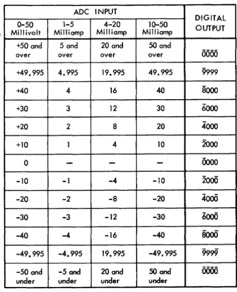
multi-plexing relays. As shown in Figure 6, an analog signal passes through a multiplexing relay contact and into the ADC (Analog-to-Digital Converter) . The converted
signal, which will be in the digital range of 0000 to
Analog-to- Digital r----~
_-+_~ ____ -+I Converter
1620
Core Storage
\
9999, remains in the ADC register until the program
causes it to be transferred to core storage. An ADC
con-version scale is shown in Figure 7. Pertinent pro-gramming details follow.
If a negative analog voltage is read into the ADC,
a flag is placed over the units digit of the ADC register
and the Negative light on the 1711 Operator's Panel is turned on. This flag bit is transferred to core storage with the units digit when the transfer from the ADC
register to core storage occurs.
If the analog signal exceeds the range of its match-ing card, four flag bits rather than the contents of the
ADC register are placed in core storage. The ADC register
and associated 1711 Operator Panel lights will contain an 8-2 or 8-2-1 bit configuration in the high-order posi-tion and 000-999 in the other three posiposi-tions depending on the value of the overload signal.
When the four digits from the ADC register are
trans-ferred to core storage, the high-order digit is flagged. The replaced data including flag bits is lost.
Once the converted data is in core storage, the pro-gram transforms the digital value into a meaningful measurement of the variable (temperature, flow rate, pressure, etc.) .
Two Program Select instructions: Select Address and Select ADC Register are available for reading analog
ADC INPUT
DIGITAL
0-50 1-5 4-20 10-50 OUTPUT
Millivolt Milliamp Milliamp Milliamp +50 and 5 and 20 and 50 and
over over over over
0000
+49.995 4.995 19.995 49.995 9999
+40 4 16 40 8000
+30 3 12 30 6000
+20 2 8 20 4000
+10 1 4 10 2000
0
-
-
-
0000-10 -1 -4 -10 2000
-20 -2 -8 -20
4000
-30 -3 -12 -30 6000
-40 -4 -16 -40 8000
-49.995 -4.995 19.995 -49.995 9999
[image:13.615.65.302.415.706.2]-50 and -5 and 20 and 50 and 0000 under under under under
Figure 7. ADC Conversion Scale
signals into the ADC for conversion. Select Address and
Select ADC Register are provided with Random Ad-dressing of TAS, a special feature. The Select Address
instruction merely reads the selected signal into the
ADC for conversion, whereas the Select ADC Register transfers the contents of the ADC register into core
stor-age first, and then reads the newly selected analog sig-nal for conversion.
The Multiplexer Busy indicator (29) is on during the 50 millisecond conversion cycle. This indicator may be interrogated to determine when conversion is com-pleted. The computer proceeds with succeeding in-structions during conversion unless an instruction that uses the multiplexer is initiated (Analog Input, Analog Output, or Contact Operate instructions) . In this case, both the instruction and the computer are delayed until after conversion is completed and Multiplexer Busy is turned off.
The Multiplex Complete indicator (40) is turned on at the end of conversion. Multiplex Complete initi-ates an interrupt which can cause reading of the ADC
register, selection of the next Analog Input address, etc. It is often desirable to take successive readings of an input variable in order to assure that no error occurred in the measuring of the variable or in the analog-to-digital conversion of the measurement. By taking three separate readings, the output of all three readings may be compared against a predetermined range. If all three readings lie within a specified range, the first reading, or perhaps an average of the three readings, may be used with more certainty as the value of the input vari-able. '!\Then this is done, a time delay of 600 ms should be programmed between successive readings of the same point to ensure maximum accuracy.
Real-Time Clock lRTCJ
The RTC designed for use in logging applications is
an electronically powered 24-hour mechanical device which keeps time (to the nearest minute) in hours, tenths of hours, and hundredths of hours. The contents of the RTC, 00.00 through 23.99, are displayed on the
1711 Operator's Panel, and may be read into core stor-age by use of the Select Real-Time Clock instruction. The low-order position clock wheel advances once each minute, as follows: 0-2-3-5-7-8-0.
The RTC may be programmed so that the logging
time is printed along with log data. To prevent the possibility of erroneous readings, readout of the RTC
is blocked during the time the clock wheels advance (approximately 320 milliseconds) .
as their respective clock wheels advance. The hun
-dredths of hours (rightmost) lever must be positioned by the clock to its upward limit of travel before it can
be used to set its clock wheel.
Terminal Address Selector
(TAS)
TAS is program-controlled to select individual process
signals. Consisting of a 300-point scanning counter and
matrix and a three-digit register, TA5 selects Analog
Input, Analog Output, and Contact Operate addresses
from 000 to 299; High-Speed Contact Sense address
from 00 to 19; and Process Operator Units addresses
from 00 to 99. TAS contents are displayed on the 1711 Operator's Panel. The Select TAS instruction Illay be
used to store the contents of TAS. For the purposes o[
programming and timing considerations, it is
impor-tant to note (see Figure 6) that Analog Input, Analog Output, and Contact Operate addresses are routed
through the Multiplexer, and that the Process Operator
Units addresses and the High-Speed Contact Sense ad
-dresses are not routed through the Multiplexer. The significance or this fact is mentioned in appropriate
parts of the manual.
1711 Operator's
Panel
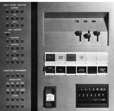
The 1711 Operator's Panel (Figure 8) contains
switches, keys, lights, and indicators that are pertinent
to opera ti ng the 1711. The Opera tor's Pa nel is
[image:14.618.42.404.360.714.2]Flexibility, a major advantage that permits the 1710 Control System to meet individual customer require
-ments, is achieved through the installation of an-nounced special features and additional units. A mini-mum 1710 Control System may be installed for existing needs, and the installed system may be altered as con-trol requirements change to provide new functions and increased capabilities. This section describes the 1710 special features and additional units. The publication IBM 1710 System Configuration (Form G26-5693) shows all special features and additional units and their pre-requisi tes.
Four types of terminal blocks are available for in-stallation in the 1712 Multiplexer and Terminal Unit: Standard Terminal Block, Thermocouple Terminal
figure 9. Terminal Block
1710 Special Features
and Additional Units
Block, Interrupt/Process Branch Indicator Terminals, and Contact Sense Terminal Blocks.
Standard Term
i
nal Block
The standard terminal block (Figure 9) may be used to connect Analog Input, Contact Operate, and Analog Output functions. The following rules must be ob-served, however:
Contact Operate and Analog Output functions may be connected on the same block. In order to minimize undesirable stray voltage effects, Analog J nput func-tions must be located on a block containing only An-alog Input functions.
Analog Output functions require two addresses for each analog output channel. In addition, two addresses must be assigned for control of the slew and trim oper-ations.
Fifty terminal addresses or 100 terminals are pro-vided for customer connections on each block.
Analog Input terminations other than thermocouple terminations can be made on a thermocouple terminal block. Analog Output and Contact Operate termi-nations can only be made on a standard terminal block.
Interrupt
/
Process Branch
Indicator Terminals
Contact Sense Terminal Block
This terminal block is used to terminate high-speed contact sense terminal points. Each block provides for termination of 50 contact sense connections.
Thermocouple Terminal Block
The thermocouple block is a standard terminal block that has been modified for thermocouple terminations. A thermocouple is a temperature-measuring device. It provides an analog voltage which is developed by the difference between the ambient temperatures of the thermocouple measuring junction and the thermo-couple block reference junction. A resistance bulb thermometer (RBT) and its associated circuit
compo-nents are mounted on the block to measure the refer-ence temperature. The RBT circuit also provides a
refer-ence voltage signal (VR)' The 1710 uses the thermo-couple, RBT~ and V R signals to compute the measured
temperature.
Analog Input terminations other than thermocouple terminations may be made on a thermocouple block. Analog Output and Contact Operate terminations can only be made on a standard terminal block.
Fifty terminal addresses or 100 terminals are pro-vided for customer connections on each block. The
RBT and V R must be assigned to the first two
(lowest-numbered) addresses on the thermocouple block.
Measuring Thermocouple
Temperatureswith the
1710
The 1710 Control System is connected to each process thermocouple via the 1712 MTU. The thermocouple
measuring junction is located in the process area where temperature sensing is desired, and the reference junc-tion is located on the 1712 terminal block. The refer-ence junction wires are extended to a matching card in the 1712. The 1710 compensates for reference tem-perature fluctuations by means of an RBT~ located on each thermocouple terminating block for reference-temperature sensing, and through calculations per-formed as part of the program.
Resistance Bulb Thermometer (RBT)
Essentially, an RBT is a wire-wound resistor whose
elec-trical resistance varies with temperature. The resistor is electrically connected to a Wheatstone bridge (bal-anced circuit) . A temperature variation causes a change in resistance and a consequent unbalance of the bridge circui t. The RBT circuit provides two signals for 1710
program evaluation: the voltage produced by the RBT,
and an RBT reference voltage. Thus, not only are
ther-mocouple signals compensated for by reference temper-ature fluctuations, but the reference tempertemper-ature signal itself is read by the computer to permit compensation for any RBT supply voltage variations that may occur.
Thermocouple Programming and Conversion
The conversion of a thermocouple signal to a meaning-ful and accurate temperature value is performed as part of the computer program. The signals from the thermo-couple and the RBT circuit, plus related thermocouple
and RBT data, provide the means for mathematical
anal-ysis and conversion. Thermocouple data is available from commercial sources for each thermocouple type, i.e., tables and curves which express the temperature-to-millivolt relationship. Data for the RBT supplied
with the thermocouple terminal block is provided be-low. Three points should be stressed about the con-version procedure which follows: (I) It is recognized that there are other means, such as curve fitting, to convert thermocouple signals, (2) The procedure be-low is valid only where the RBT supplied with the
ther-mocouple terminal block is used, and (3) This pro-cedure pertains to the signal conversion of only one thermocouple type, i.e., constants A, B, C, and D (see below) must be computed and stored for each ther-mocouple type:
This segmentation is required because thermo-couple millivolt output is not a straight line rela-tionship with respect to measured temperature-particularly at the upper end of the thermocouple temperature range. Smaller segments, of course, provide a more linear or straight line approxima-tion.
2. Take the upper and lower millivolt values from each segment, and use the relationship, I millivolt equals a DRO (digital readout) value of 200, to obtain equivalent DRO values. The DRO value for a given thermocouple signal is the same as the digital value obtained in the ADC register for
that same thermocouple signal. For example, a 15-millivolt value is equal to a DRO value of 3,000
(15 X 200) and, where the ADC range is +50
mil-livolts, a 15-millivolt thermocouple signal is con-verted to 3,000 by the ADC. Since all thermocouple
signals are converted to digital values, the use of DRO values rather than millivolt values facili-tates the computation of actual temperatures. 3. For each segment, use the formula
temperature = A (DRO)
+
Btwice to solve for A and B, the two unknowns, i.e., solve once for the upper temperature and DRO values and once for the lower temperature and DRO values. Actually, A is the slope of the segment and B is the intersection of the segment, if extended on the y-axis.
4. Store A and B for each segment.
5. Use the same formula (step 3) to solve for A and B in the temperature area of 250 C, which is the normal temperature region for the RBT
(approxi-mate room temperature). Use these A and B values in the following formulas
B D = - j \
These two formulas express the thermocouple block RBT relationship to the thermocouple
sig-nal; C and D are used for the linear conversion from temperature to DRO of the computed RBT
temperature (step 8) .
6. Store C and D. You now have stored: (1) a pair of constants, A and B, for each segment of the curve, and (2) constants C and D for the base temperature of the RBT.
7. Read both signals of the RBT circui t and use their ADC values in the formula
RBT RBTt = 28.82 (RBT
r
)
+
5.0to solve for the RBT temperature (RBTt ) . RBT
and RBTr are the ADC values obtained by
read-ing the RBT signal and the RBT reference signal
(the first two addresses on the thermocouple block). The values, 28.82 and 5 (expressed in degrees Centigrade), are constants for the RBT
supplied with the thermocouple block. These values must be converted to degrees Fahrenheit if the thermocouple tables and curves are ex-pressed as such (F
=
9/5 (C)+
32) .8. Use the formula
CRBT = C (RBTt )
+
Dto obtain a corrected DRO value for the RBT
(CRBT). C and D were obtained in step 5; RBTt was obtained in step 7.
9. Read the thermocouple signal, and use its ADC
value in the formula
ATC=TC
+
CRBTto obtain an adjusted DRO value (ATC). ] 0. Use the formula
TCt =A(ATC)
+
Bto compute the actual thermocouple temperature
(TCt ) . A and B are selected according to the
DRO value of ATC, i.e., whatever segment the value of A TC falls into, the A and B values are used from that segment.
Example of Thermocouple Conversion
Example: An iron-constantan (type
J)
thermocouple is installed in a temperature region of 8000 C. The Aand B values for the segment that includes 800°C are: A = .07803, B = 89.554. The A and B values for the segment that includes 25°C are: A
=
.096], B=
.385.From step 5: C = 10.4 and D = -4.0
Assume the RBT temperature (RBTt ) IS 25°C; then
from step 8:
CRBT=256.0
Assume the ADC or DRO value of the thermocouple is 9236; then from step 9:
ATC = 9492
High-Speed Contact Sense
High-Speed Contact Sense, available as a special feature, gives the 1710 the ability to determine the status of on/off conditions in the process area. It is especially suited for control system applications that require very fast sensing of process contacts and for reading the many types of contacts used in industrial processing. Contact sense points are available in incre-ments of five, with a maximum of 400 on anyone system.
Description
Contact sense points are terminated in blocks of 50 points each. One terminal address is assigned for a group of 20 terminal points. A total of 20 terminal addresses is available if all 400 contact sense points are installed. For the purposes of programming, the ter-minal block can be thought of as consisting of two parts with 200 terminal points (lO terminal addresses) on each part. When a program instruction specifies anyone of the 10 terminal addresses on either part, the 20 terminal points at that address and all of the terminal points tor the remaining higher-numbered terminal addresses tor that part are scanned and read into core storage. For example, in the following chart of terminal addresses it can be seen that an instruction specifying terminal address 03 causes the program to scan and read into core storage terminal points 60 through ] 99.
Terminal Points Terminal Points
Addresses Scanned Addresses Scanned
00 000-199 ]0 200-399
01 020-199 11 220-399
02 040-199 ]2 240-399
03 060-199 ]3 260-399
04 080-199 14 280-399
05 ] 00-199 15 300-399
06 120-199 16 320-399
07 ] 40-199 17 340-399
08 ] 60-199 18 360-399
09 180-199 19 380-399
As another example, terminal address 10 would cause the program to scan and read into core storage terminal points 200 through 399; thus, up to 200 terminal points can be read with one instruction.
Contact points are scanned and read into core stor-age at the rate of 100,000 points per second. When fewer than 200 points are scanned, the rate is less than 100,000 points per second.
Table 1 contains examples of actual scanning rates. The program instruction associated with the High-Speed Contact Sense special feature is Select Contact Block.
Table I. Examples of High-Speed Contact Sense Scanning Rates
Number of Number of Time in Scanning Rate Points Computer Microseconds in Points Scanned I nstruct ions per Second
20 1 335 59,000
100 1 1,035 96,000
200 1 1,910 105,000
400 2 3,820 105,000
Contact Operate
The Contact Operate feature enables the 1710 to con-trol on/off conditions in the process area. Motor start-ups, annunciators, horns, alarms - any device which can be controlled by a momentary contact closure may be programmed.
Contact Operate functions are available in incre-ments of two. They may be terminated on the same terminal block with Analog Output functions, but not with Analog Input. The special feature, Random Ad-dressing of TAS) is required. Contact Operate utilizes mercury-wetted relay switches for its operation.
Application
A simplified Contact Operate circuit is shown in Figure ] 0 to point out the following:
]. Customer power is used to operate a customer's device (an alarm in this case) - the Contact Oper-ate function merely completes the circuit. The contact capacity is 100 volt-amperes with a 2-am-pere, 120-volt AC or 24-volt DC maximum. Note
that the contact lines are fused within the 17] 2. 2. The customer's relay is energized when the
Con-tact Operate instruction is executed. The relay contact R-l closes and the alarm is activated. 3. The customer relay circuit mayor may not be
self-latching. The relay shown is latched, that is, held energized by its R-2 points. An unlatching method such as a push button may be provided by the customer.
4. Adequate arc suppression must be provided by the customer for contact protection. For addi-tional information, refer to IBM 1710 Control Sys-tem Installation Manual - Physical Planning
Contact Operate Function
latching Relay
I
R-2~~~~~
____________
Q)_I~~----~r-
____
-+ ____~
__ +-__~
17121 Process
[image:19.621.67.514.473.708.2]o
Circled numbers refer to textFigure 10. Contact Operate Logic
Contact Operate Programming
The Contact Operate instruction Select Address and Contact Operate initiates a contact closure of 50 ms. The Multiplexer Busy indicator is on during this time.
If the multiplexer is busy when the Select Address and Contact Operate instruction is initiated, the instruc-tion is delayed until the Multiplexer Busy indicator goes off. The computer is disconnected 160 fLsec after initiating the instruction. 1£ the computer is discon-nected before an instruction using the multiplexer is initiated and before completion of the 50 ms interval, the instruction is delayed for the remainder of the 50
~~
Controlling
I
Actuators
~I
Process 1Instrumentation 1
+
I
Set-PointI
PositionersProcess Area
-
-
- Control System-I
Analog Contact1712 MTU
Output Operate
I
1711t
1
1620Figure 11. On-Line, Closed-Loop Control
ms. 1£ the Input/Output Interrupts special feature is installed, a Multiplex Complete Interrupt signal occurs after the 50-ms interval.
Analog Output
The Analog Output feature enables process engineers to "close the loop" with the IBM 1710 Control System.
Process instrumentation provides data to the computer which, after programmed analysis of the collected data, returns controlling signals to the process via the Analog Output and Contact Operate features (Figure 11) . All
Measuring Instruments
-
-High-Speed Analog
I
Contact Sense Input
process instrumentation, both measuring and controll-ing, is provided by the customer, as are the set-point positioners, to alter the set-point adjustments on con-trolling instrumentation. The controllers regulate the actuators (valve motors and valves, dampers, relays, solenoids, etc.) that implement process control.
The Analog Output feature has been designed so that the customer has maximum control over his out-put functions.
Controlling Instrumentation
A home furnace thermostat is a controlling instrument. Depending on feelings of coolness or warmth, the householder adjusts the thermostat (set-point) up or down. The difference between the room temperature and the temperature specified by the set-point causes a signal that controls the fuel supplied to the furnace. The resulting change in BTU output from the furnace
corrects the room temperature to the temperature spec-ified by the set-point.
Industrial controlling instruments are generally more complex, but contain essentially the same ele-ments:
A device for measuring the value of variable. An adjustable set-point.
A control mechanism for maintaining the meas-ured variable at the value specified by the set-point.
In addition to these basic elements, a controlling in-strument mayor may not have associated with it an indicator and/or a recorder. An indicator provides a continuous visual indication of the measured variable, e.g., the thermometer mounted on the home thermostat.
I
Set Point
Flow Recorder Controller
}'igure 12. Automatic Control Loop
A recorder provides a continuous record of the meas-ured variable. Controlling instruments are generally named according to the scope of their functions - re-cording, indicating, and controlling. For example, an instrument consisting of all three units is referred to
as an Indicator/Recorder Controller; an instrument consisting of a recorder and a controller is referred to as a Recorder-Controller, etc.
A basic automatic control loop for regulating fluid flow is shown in Figure 12. The variable is measured and transmi tted to the Flow Recorder-Con troller by Flow Transmitter 1. The controller~ which mayor may not be mounted inside the instrument, acts as an analog computer in that it determines the difference between the measured variable and the set-point value. This difference, if present, results in a corrective signal to the actuator or controlling valve, V. Thus, the fluid flow is maintained at the value specified by the position of the set-point. When the process requires a change in flow rate, the process operator repositions the set-point up or down.
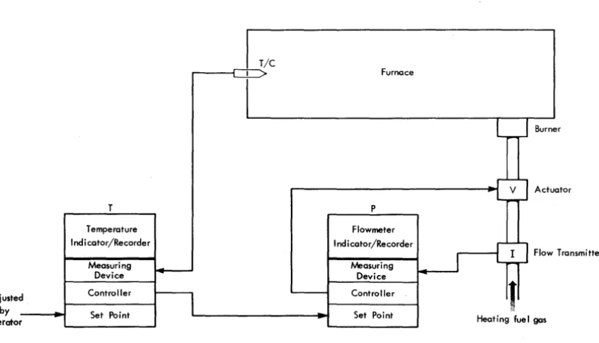
Most process instrumentation set-points are adjusted by the operator. Some control problems, however, re-quire that the set-point of an instrument be automati-cally adjusted by the controller of another instrument. This form of control is designated as Cascade or Mul-tiple-Loop control. Cascade control may be employed to regulate the supply of fuel to a steel-mill furnace. The fuel, coke oven gas, is obtained as a byproduct of another operation and as a result its pressure in the fuel line varies considerably. The demand for furnace heat also varies and Cascade control is employed to compensate for both variables (Figure 13). Fluctua-tions in furnace temperature are sensed by the thermo-couple (T / c) . The temperature Indicator /Recorder, T,
uses the T / C signal to determine the furnace
tempera-ture. Differences between the furnace temperature and the set-point value of T (note that the set-point is ad-justed by the operator) cause appropriate adjustments of the set-point on the fuel Flowmeter Controller, P. Fluctuations in fuel pressure cause flow rate changes which are sensed by Flow Transmitter I. Differences between the fuel flow rate and the Cascade-controlled set-point on P cause appropriate adjustments of the actuator V.
Set-Point Positioners
Set-Point Positioners (sPp's) are controlled by the 1710, and they, in turn, control the controlling instruments as shown in Figure II. An spp is required for each con-trolling instrument, and like T in Figure 13, each spp provides a signal to control the set-point and therefore permit computer control of its associated controlling instruments. The principal advantage of 1710 control is its ability to control many controlling instruments simultaneously. Process conditions are rapidly moni-tored and simultaneously analyzed and, based on this analysis, spp's are individually selected and simulta-neously adjusted for optimum process control.
A set-point positioner has an up motor and a down motor for up scale- and down-scale adjustments of its set-point. The up and down motors are individually operated, as determined by computer analysis of
proc-ess conditions. The up or down adjustment of a set-point causes a corresponding adjustment of its associ-ated controlling-instrument set-point.
Adjusted
by
operator
T
Temperature Indi cator/Recorder
Measuring Device
Controller
Set Point
Figure 13. Cascade Control
Closed-Loop Computer Control
Some Indicator /Recorder Controllers used with closed-loop computer control contain a three-position switch. These positions are labeled Cascade (or Computer), Automatic, and Manual. Others do not include the Cascade position.
Manual
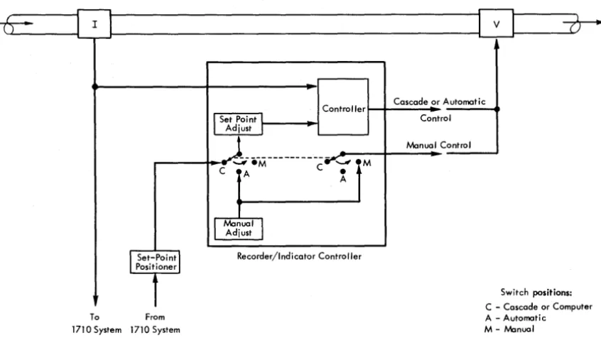
With the instrument switch on Manual, the Indicator / Recorder Controller is removed from closed-loop con-trol of the process variable. The valve position is com-pletely under control of the process operator. If any change in the valve position is necessary, the controlling signal to V is supplied through the manual adjustment knob (Figure 14). Thus, a means of operator control is available irrespective of instrument or computer mal-function. Switching from Automatic to Manual or Manual to Automatic usually requires some adjust-ment or matching by the process operator to avoid bumps.
Automatic
With the instrument switch on Automatic, the auto-matic control loop shown in Figure 12 is in effect. Set-point adjustment is under control of the process op-erator rather than the SPP (Figure 14) .
On automatic Indicator/Recorder Controllers not equipped with a three-position switch, i.e., without a Cascade (or Computer) position, the SPP signal goes directly to the set-point adjustment control. On some
Furnace
P
Flowmeter
I ndi cator/Recorder
Measuring Device
Controller
Set Point
Burner
Actuator
Flow Transmitter
[image:21.618.85.508.474.716.2]-IT-
I
II
I
vI
()" - - - - J ' - - - '
Controller Cascade or Automatic
I
Set Point IAdjust I
~---
..., eM C '-'" 4C A e
A
l
ManualJ
AdjustI
Set-Poin~I
Recorder/Indicator Controller Positioner1
To From
1710 System 1710 System
Figure 14. Controlling Logic
control loops an isolation switch or valve, which in effect duplicates the function of the Cascade switch described above, must be installed. Each individual situation must be investigated to determine whether such additional switching or valving is required, de-pending on the manufacturer of the instrument and the particular arrangement of the installation.
Cascade (or Computer)
Some Indicator/Recorder Controllers are designed to operate as Cascade Controllers. With the instrument switch on Cascade, the set-point is automatically adjusted with signals supplied from outside of the controller according to computer analysis of process conditions. As shown in Figure 14, the signal from the Flow Transmitter I is sent to both the controller and the 1710. If the signal is pneumatic, the customer must provide a transducer to convert the signal to the re-quired electrical range of the 1710. Based on program analysis of process data, including the signal from I, the 1710 sends controlling signals to the SPP. The SPP~ in turn, provides a signal through the Cascade switch position to adjust the set-point (the broken line be-tween the two switches signifies that both operate from the same manual switch - they are not connected elec-trically) . The SPP must provide the same type of signal, electrical or pneumatic, as 1. The controller, differen-tiating between the new set-point position and the signal from I, sends a signal to V which alters the fluid flow.
Control
Manual Control
M
Switch positions:
-C Cascade or Computer A - Automatic M - Manual
Analog Output Logic
There are two TAS (Terminal Address Selector) ad-dresses for each spp ~ an up address and a down address, and, in addition, one TAS address for selection of the slew signal and one T AS address for selection of the trim signal. Only one slew addres~ and one trim address are required, regardless of the number of SPP's. However, the slew and trim addresses should be consecutive and so numbered that they can be assigned to the same matching card.
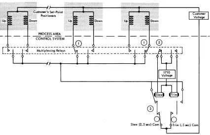
An Analog Output logic diagram is shown in Figure 15. The circled numbers refer to the numbers in text that follow.
]. The program determines from the collected data which spp's require slewing and what the direc-tion of each is, up or down. The multiplexing relay is latched for each up and down address selected. 2. The slew address is selected, and the 1710 voltage
supply causes energization of the slew relay. 3. With the slew relay picked and the 2.5-second
[image:22.620.39.462.65.303.2]Figure 15. Analog Output Logic
Analog Output multiplexing relays and the Ana-log Output Check circuit tests to be sure all multi-plexing relays are unlatched (Figure 16) . Program re-selection of spp's which require additional
slew-ing or trimmslew-ing begins. This description (steps 1 through 3) continues until all slewing and/or trimming operations are completed.
Analog Output Timer
The Analog Output Timer is located in the 1712 MTUJ and consists of a continuously running motor, circuit breakers, control relays, and associated circuitry. The
r-=---
3.6 Second AD Cycler.7.ec--r-2.S ,ec--___
.~ISetup _ _ _ _ _ ...
•
Slew _ _ _ _ _ _ _ _ _ _ _
. 1-.5 sec-I TrJm _ _ _ _ ~.,;
Reset_
[image:23.612.73.499.70.343.2]Analog Output Check Figure 16. Analog Output Timings
timer provides the following electrical pulses:
Setup. At the beginning of each Analog Output cycle, .7 seconds are allowed for the program selection of spp
addresses.
Slew. A pulse duration of 2.5 seconds is provided for driving the spp motors.
Trim. A pulse duration of .5 seconds is provided for driving the spp motors. spp motors may be either slewed
or trimmed in anyone Analog Output cycle, but not both. Note the nominal 5-1 ratio between slew and trim. A slew operation moves the spp set-point five times as
far as a trim operation.
Reset. Following a slew or trim operation, a reset pulse is provided to drop out the Analog Output multi-plexing relays. These relays, previously selected during setup time, are latch-type relays, i.e., once selected, they stay latched until reset.
Analog Output Check. Following a reset pulse, the Analog Output Check pulse tests to be sure that all Analog Output multiplexing relays are unlatched. A latched relay would cause the Analog Output Check indicator (23) to be turned on.
Analog
Output
ProgrammingThe IBM Analog Output program provides for three
before adjustment, (2) spp adjustments are synchro-nized by adjustment rate variation, and (3) spp's are automatically adjusted (slewed and/or trimmed) . The Select Analog Output and Signal instruction provides for SPP selection and operation.
SPP Set-Point Determination
Increased Analog Output accuracy is obtained when the precise setting of each spp is known before adjust-ment. Several methods may be used to keep track of spp settings: The computer can start with the original setting and progressively add and subtract each up and down adjustment, or it can read a feedback signal from either the spp or the controlling instrument (an Analog Input address is necessary for each feedback signal) . This latter method offers greater accuracy.
However, where the control loop is such that it is known that the offset between set-point and the proc-ess variable will be negligible, it is sufficient just to read the valve of the process variable and assume its position is equal to the set-point of that control loop.
SPP Adiustment Synchronization
A stored table is used to facilitate programmed syn-chronization of spp adjustments. The table includes the desiTed setting, the actual setting, the
%
of slew, the%
of trim, the feedback setting, and the rate change. The rate change is the frequency with which an spp is to be adjusted. For example, a rate change of four initiates a slew or trim every fourth 3.6-second Analog Output cycle. The fastest rate change is determined by the customer by proper selection of his SPP. Slowerrates of change can then be accomplished by the rate change program in the 1710.
Programmed Set-Point Positioner Adiustment
The desired SPP setting, determined by computer calcu-lations, is compared with the actual setting. If the difference between the desired and actual settings ne-cessitates one or more slew operations, a "Slew indi-cator" is turned on. The Slew indicator is strictly a program indicator (digit or no-digit in core storage) ; it is used as a slew or no-slew guide. Calculations re-move the digit when the desired SPP setting is either
achieved or so close to being achieved that another slew would be too much. The trim operations and a "Trim indicator" are programmed in a similar manner. Analog Output Setup IndicatoT (28). A Setup indi-cator, which is turned on and off with the setup circuit breaker in the Analog Output timer (see Figure 16), is provided for program interrogation; up or down or trim operations should not be initiated unless this indicator is on. The ON condition of this indicator is
the only means that the program has of determining that a full 2.5 seconds is available before the Analog Output multiplexing relays are reset. For example, if an up or down address is selected during slew or trim time, the selected spp will be operated less than a full slew or trim cycle. Execution of a slew or trim instruc-tion also turns off the Setup indicator.
Reset Conditioning. The program is not actually limited to .7 seconds of setup time. The reset pulse is conditioned so that it occurs only if a slew or trim has been initiated. Thus, additional 3.6-second Analog Output cycles may be used for setup time. The SPP is
not operated until the slew or trim instruction is exe-cuted.
Analog Output Check Indicator. The Analog Out-put Check indicator (23) is turned on if an Analog Output multiplexing relay fails to unlatch when the reset pulse occurs. The program interrogates this indi-cator at the end of every Analog Output operation. If the Basic Interrupt special feature is installed, an inter-rupt is initiated when this indicator is turned on.
Analog Output Fail-Sale
FeaturesProgramming Protection. The Analog Output pro-gram and the Analog Output Check indicator prevent erroneous slewing or trimming of spp's if an Analog Output multiplexing relay fails to unlatch. The pro-gram initiates an "open the loop" action.
The ratio between the duration of slew and trim pulses has been established to avoid process upsets by sudden undesirable set-point changes.
Set-point positioners are designed so the operator can observe what the computer is doing to the set-points, and, therefore, can easily take over control ot a set-point positioner with a minimum of delay.
If there is a power failure, the set-point positioner stays at, or very close to, its last position and cannot advance farther than the slew 01 trim adjustment in
operation at the time of the failure.
The internal data checking features of the 1710 Con-trol System are programmed to log and bypass inter-mittent errors. When internal checking reveals that effective control system operation is impossible, a "re-turn to manual operation" is initiated (see ANY CHECK
in the Interrupt section) .
SPP Adjustment Limiting. Most spp's are provided with mechanical stops which prevent adjustments be-yond the limits specified by the stops themselves. For example, an spp with a range of 0-100 cannot be slewed and/or trimmed beyond the 60-80 range if the stops are manually positioned at 60 and 80. Thus, neither SPP
nor 1710 malfunctions can cause SPP settings to exceed
Power Failure Protection. If a power failure occurs, the spp's are inoperative, except upon manual inter-vention. Thus, instrumentation set-points cannot be falsely altered as a result of power failures.
Interrupt
The Interrupt feature gives the 1710 the ability to recognize conditions demanding immediate attention. The disturbance (interrupting condition) causes the computer to suspend routine operation. In an open-loop system, the control room operator is notified of the disturbance by the console typewriter. A closed-loop system can actually initiate corrective action as well as notify the control room operator or the process operator.
Interrupt Modes
of Operation
The 1710 normally operates in the interruptible mode,
that is, it interrupts the main program when an inter-rupt condition occurs. However, once the interinter-rupt is recognized, the 1710 is in the noninterruptible mode
until the interrupt subroutine has been completed. In other words, an interrupt cannot interrupt another interrupt until the appropriate action required by the first interrupt has been completed. Interrupts are serv-iced in the program in a sequence that corresponds to the priority established for them by the process engi-neer. Four interrupt instructions, Branch Out (of non-interruptible mode), Branch Out (of nonnon-interruptible mode) and Load, Mask, and Unmask, are provided with this feature for interrupt control. The Branch Out and Branch Out and Load instructions are used to end an interrupt subroutine and to place the 1710 in the interruptible mode. The Mask instruction is used to mask all interrupts, i.e., it places the 1710 in the non-interruptible mode, delaying all interrupts until the interruptible mode is restored. The Unmask instruc-tion is used to restore the interruptible mode when the noninterruptible mode exists as a result of a Mask instruction.
Figure 17 shows the relationship between the four interrupt instructions and the two interrupt modes. Starting at the top (progress in time is shown from top to bottom) interrupt 1 causes the 1710 program to branch to interrupt subroutine 1 and to enter the non-interruptible mode. A Branch Out or Branch Out and Load instruction returns the 1710 to the main program and the interruptible mode. A Mask instruction places the 1710 in the noninterruptible mode, also causing interrupt 2 to be delayed (not lost) until the Unmask instruction is executed. The 1710 then enters the
inter-ruptible mode long enough to recognize interrupt 2; this causes an immediate return to the noninterruptible mode and the interrupt 2 subroutine. With the 1710 in the noninterruptible mode, as a result of interrupt 2, the Unmask has no effect, and the Branch Out. or Branch Out and Load returns the 1710 to the main pro-gram and the interruptible mode. Interrupt 3 causes the 1710 to branch to interrupt subroutine 3 and to enter the noninterruptible mode. Execution of the Mask instruction during interrupt subroutine 3 keeps the 1710 in the noninterruptible mode even after the Branch Out or Branch Out and Load has returned the computer to the main program. Any interrupts occurring after the Mask instruction are delayed, not only until a Branch Out or Branch Out and Load instruction is executed but until an Unmask restores the computer to the interruptible mode.
Interrupt 1
Int~r:r:oo~
__
~n:~=t;ble
_---J-Branch Out or
J
Branch Out
Mask _ _ ....
~,
_ _ _ _ _ _ _ _~
and LoadInterrupt 2 ~-.... ~ No Effect
I No effect
I at this time
I
L-__
~~z~~:=:-=.;:!~unmask
~Unmask
(no effect)
~--- - - ~BranchOutor
1
Branch Out
and Load
Interrupt3--... ~ - - - ~ ~Mask
~
Branch Out or Branch Out and Load (1710 returns to main
program but stays
in Noninterruptible
Mode because of mask)
[image:25.613.331.571.314.699.2]r---
.... UnmaskExternal
and
Internal InterruptsExternal interrupts are interrupts that occur as the result of conditions in the process. These interrupts cause the 1710 to give almost immediate attention to a situation or occurrence in the process whenever re-quired.
Internal interrupts originate within the 1710 Con-trol System and facilitate the concurrent handling of many programs.
External Interrupts
A maximum of twelve external (process) interrupts are available with the External Interrupt feature. An in-dicator is provided for each interrupt. Once an inter-rupt indicator is turned on by its related interinter-rupt, it remains on until it is interrogated by the program. The External Interrupt indicators are assigned indi-cator codes 48 through 59.
Internal Interrupts
Nine internal interrupts are available in groups of three, as follows:
Basic Interrupt Feature
Operator Entry (18)
Any Check (19)
CE (Customer Engineer) Interrupt (27)
Input/Output Interrupts Feature
Multiplex Complete (40)
Seek Complete (42)
Any slOe (Serial Input/Output Channel) (45)
Timed Interrupts Feature Analog Output Setup One Hour
One Minute
(41 ) (44) (43)
An indicator is provided for each interrupt listed above, and is identified by the number in parentheses. An interrupt condition turns on its associated indica-tor, which remains on until program recognition occurs.
Operator Entry Interrupt (Indicator 18). The Oper-ator Entry interrupt provides for the entry of data pre-viously set in the seven Manual Entry switches on the 1711 Operator's Panel. When the process opera tor posi-tions the Manual Entry switches and presses the Oper-ator Entry key, the OperOper-ator Entry indicOper-ator turns on and the computer branches to the program subroutine that causes the contents of the Manual Entry switches to be read into core storage.
This indicator is a basic feature of the system; its interrupt function is available as part of the Basic Interrupt feature.
Any Check Interrupt (Indicator 19). The Any Check indicator (19) is turned on by any of nine error con-ditions shown here:
Read Check Indicator 06
Write Check Indicator 07
MAR Check Indicator 08
MBR-E Check Indicator 16
MBR-O Check Indicator 17
TAS Check Indicator 21*
Function Register Check Indicator 22*
Analog Output Check Indicator 23*
Any Disk Check Indicator 39*
*These indicators are available only if their associated special features are installed on the system.
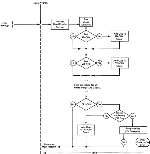
When one of these errors occurs, the Any Check in-terrupt is initiated and the computer can branch to the Interrupt Identification routine (Figure 18). (Thus, all of the indicators shown above initiate an interrupt, through the Any Check interrupt.) This routine identi-fies the interrupt and initiates a branch to the Any Check Interrupt subroutine or Error Analysis subrou-tine. The programming philosophy of this subroutine is to keep the process in operation, regardless of errors, if at all practical. Thus, as shown in the logic diagram (Figure 18), each error check is tested individually with a Branch Indicator instruction, and, if that cator is on, a one is added to the count of that indi-vidual error. The count of each type of error can be reviewed by the IBM Customer Engineer during
diag-nostic testing and analysis. Note that the TAS error is
handled differently if the error occurs during an An-alog I/O operation - here, the anAn-alog instruction will repeat until it is executed correctly or until three con-secutive errors occur. When three concon-secutive TAS errors
occur on an analog input or output operation, It IS
assumed that the control system is unreliable, and system o