http://dx.doi.org/10.4236/ojfd.2015.54031
Control of Transonic Shock Wave
Oscillation over a Supercritical Airfoil
Muhammad Rizwanur Rahman
1, Mohammad Itmam Labib
1,
Abul Bashar Mohammad Toufique Hasan
1, Mohammad Saddam Hossain Joy
1,
Toshiaki Setoguchi
2, Heuy Dong Kim
31Department of Mechanical Engineering, Bangladesh University of Engineering and Technology (BUET),
Dhaka, Bangladesh
2Institute of Ocean Energy, Saga University, Saga, Japan
3Department of Mechanical Engineering, Andong National University, South Korea
Received 11 September 2015; accepted 3 December 2015; published 7 December 2015
Copyright © 2015 by authors and Scientific Research Publishing Inc.
This work is licensed under the Creative Commons Attribution International License (CC BY). http://creativecommons.org/licenses/by/4.0/
Abstract
In the present study, a numerical investigation is carried out on the aerodynamic performance of a supercritical airfoil RAE 2822. Transonic flow fields are considered where self-excited shock wave oscillation prevails. To control the shock oscillation, a passive technique in the form of an open rectangular cavity is introduced on the upper surface of the airfoil where the shock wave oscillates. Reynolds Averaged Navier-Stokes (RANS) equations have been used to predict the aerodynamic behavior of the baseline airfoil and airfoil with cavity at Mach number of 0.729 and at angle of at-tack of 5˚. The aerodynamic characteristics of the baseline airfoil are well validated with the available experimental data. It is observed that the introduction of a cavity around the airfoil up-per surface can completely stop the self-excited shock wave oscillation and successively improve the aerodynamic characteristics.
Keywords
Transonic Flow, Shock Oscillation, Passive Control, Airfoil
1. Introduction
flow conditions, periodic self-sustained shock oscillations with large amplitudes are observed. This large scale shock induced oscillation has many undesirable unsteady effects including fluctuations in lift and drag coeffi-cients, aero acoustic noise and vibration, buffeting, aileron buzz, periodic flows in supersonic intakes, cascades and so on. Tijdeman [1] classically determined the three possible modes of self-excited shock motion for an air-foil with an oscillating flap. These were self-sustaining in a manner that the motion is maintained without the supply of external energy. McDevitt et al. [2] and Levy [3] performed an experimental and theoretical investiga-tion on unsteady flow behavior at transonic speeds over an 18% circular-arc airfoil. Supercritical airfoils could also experience self-sustained unsteady shock oscillation despite the fact that they have been developed to in-crease drag divergence Mach number. Alshabu and Olivier [4] studied the properties of BAC3-11 supercritical airfoil and found the existence of upstream moving pressure around the airfoil surfaces. Recently, Zhao et al. [5] performed an experimental study on shock oscillations over SC (2)-0714 supercritical airfoil and found that the phenomenon was two dimensional in the symmetric plane.
Several approaches have been employed in recent years to reduce the shock wave strength as well as for the control of shock oscillation. Qin et al. [6] numerically demonstrated the effectiveness of some active shock con-trol mechanism such as suction, blowing and the benefits and drawbacks of these active concon-trol techniques have been addressed. Hasan et al. [7] in their recent study showed that the use of moist air was useful to reduce the intensity of shock induced oscillations in transonic flow regimes. Stanewksy [8] extensively studied various conventional means of flow control in case of moderate to large aspect ratio wings, delta wings. Li et al. [9] proposed micro-blowing as another flow control technique. However, these active flow control methods are not always economically viable. Passive shock control techniques such as local geometrical changes in airfoil sur-face have been employed due to their economic benefits. Ashil et al. [10] incorporated shock control bump (SCB) in NLF airfoils. It has been shown that airfoil with SCB provides higher lift, lower drag, and delayed buffet onset which results in improved aerodynamic performance. The ability of SCB to control the unsteady shock induced oscillation has been reported by Hasan and Alam [11]. Mazaheri et al. [12] numerically opti-mized the SCB for shock/boundary layer interaction control in a transonic airfoil and it has been shown that the airfoil with SCB reduces the wave drag while improving the boundary layer velocity profiles downstream of the shock wave.
Another passive method is the use of a shock control cavity (SCC) on airfoil surface. Bahi et al. [13] experi-mentally demonstrated SCC concept on a supercritical airfoil for reducing drag. McCormick [14] showed that the passive cavity significantly reduced the total pressure loss. Very recently, Rahman et al. [15] showed that the airfoil with cavity significantly reduced the flow field unsteadiness such as the amplitude of pressure oscillation and root mean square of pressure oscillation in case of transonic internal flow application. Other passive control techniques such as local slots and grooves and perforated plates have been studied to improve the aerodynamic performance of airfoil [16] [17]. In addition to these shock control techniques, a hybrid flow control method based on bump and suction and injection in transonic flow fields has been tested recently [18].
Though there have been a great deal of researches on the control of shock wave, the control mechanism has still been remained unknown. Beside these, authors have found a lack of extensive study on the prospect of shock control cavity (SCC) as a passive means to control the shock wave oscillation over a supercritical airfoil. This paper numerically investigates the shock control mechanism by introducing an open rectangular cavity on the surface of a supercritical airfoil RAE 2822. Three different geometries of the rectangular cavity are investigated. Different aerodynamic characteristics of the airfoil with cavity are compared with that of the baseline airfoil.
2. Numerical Methods
2.1. Governing Equations
The transonic external flow field around RAE 2822 supercritical airfoil in the present investigation is governed by time dependent, compressible, viscous form of the fluid flow conservation equations. For simulating the compressible flow, the total energy equation including viscous dissipation is also included and coupled to the set with the perfect gas law. The thermodynamics and transport properties for air are held constant; their influence is not found to be significant. To capture the turbulence in the flow field, Menter’s SST k-ω model [19] is used in present computations. The molecular viscosity is assumed to obey Sutherland’s law of viscosity which is based on kinetic theory of ideal gases and an idealized inter-molecular force potential.
scheme while second order upwind scheme is used to discretize density and momentum terms. For the time de-rivatives, an implicit multistage time stepping scheme, which is advanced from time, t to time, t + Δt with a second order Euler backward scheme for physical time and implicit pseudo-time marching scheme for inner ite-ration, is used. A time step size of 10−5 s is used which is found sufficient for this type of unsteady computation. A solution convergence is obtained when the residuals for each conserved variables reduced below the order of magnitude 10−6.
2.2. Computational Domain and Boundary Condition
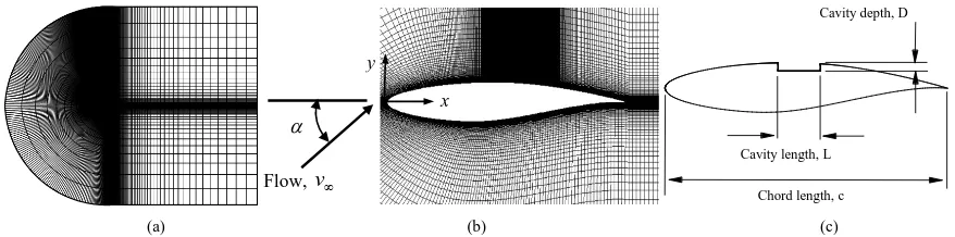
C-topology structured mesh is used to discretize the computational domain of RAE 2822 airfoil. The chord length, c of the airfoil is 610 mm. The upstream and downstream boundaries are located at 11.5c and 20c apart while the top and bottom boundaries are 12.5c apart from the airfoil surface. These distances are found sufficient to apply free stream condition at the outer boundaries. No-slip boundary conditions are applied at the airfoil surfaces. The computational domain and a zoomed view of the grids in the vicinity of the airfoil can be seen in Figure 1(a) and Figure 1(b) while Figure 1(c) shows the airfoil with shock control cavity. The free stream Mach number is kept constant at 0.729 and angle of attack, α = 5˚. The free stream pressure and temperature are considered to be 101,325 Pa and 300 K, respectively. Very fine grid spacing is used to ensure the computational accuracy. The first grid above the airfoil surface is kept in such a location which results y + less than 1.0. Com-putations with various grid sizes are initially performed to find out the optimum grid size to solve the present problem. Finally, a grid size of 76,000 is considered for all the computations which ensure a grid independent solution.
3. Results and Discussion
3.1. Computational Validation
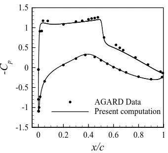
Before going to the detail discussion on present study, the computational results of transonic flow over RAE 2822 supercritical airfoil have been validated with the available experimental test data from AGARD case A6 [21]. In the present two-dimensional computation, the free-stream Mach number and angle of attack are empiri-cally modified to eliminate the influence caused by the walls of the wind tunnel and to match the wind-tunnel results. The flow parameters are corrected according to the method proposed by Coakley [22] and the corrected flow conditions are given in Table 1. Similar transonic flows have been computed numerically by Yu et al. [23]. Thus, results obtained from present computation in case of baseline RAE 2822 airfoil have been compared with the experiments of AGARD and other numerical approaches. Table 2 shows that both the aerodynamic coeffi-cients Cl and Cd have been predicted well with wind-tunnel test results of AGARD [21] as well as with the nu-merical results of Yu et al. [23]. Further, the distribution of surface pressure coefficient is shown in Figure 2. In general, the distribution obtained from present computation is in good accordance with the experimental data of AGARD [21]. The shock location is also found identical.
However, a slight difference in magnitude of pressure coefficient from experimental one is observable, which is obviously created due to the complexities in real flows, the main flow non-uniformity and the sidewall boun-dary layers, which are never taken into account in usual numerical computation.
At free stream Mach number of 0.729 and α of 2.79˚, the transonic flow field was found to be steady with no shock wave movement as observed by AGARD [21] and Yu et al. [23]. However, in the present study, the angle
[image:3.595.94.533.596.705.2](a) (b) (c)
Figure 1. (a) Computational domain; (b) close view of grids in the vicinity of baseline airfoil; (c) airfoil with cavity.
α
Flow, v∞
x y
Cavity length, L
Cavity depth, D
Figure 2. Distribution of surface pressure over baseline RAE 2822 airfoil (M∞= 0.729, α = 2.79˚).
Table 1. Corrected flow conditions.
Parameter Value
Mach number, M∞ 0.729
AOA, α 2.79˚
Free stream static pressure, p0 101,325 Pa
[image:4.595.230.400.82.237.2]Free stream temperature, T0 300 K
Table 2. Experimental and computational data for RAE 2822 (baseline).
Method AOA Cl ΔCl(%) Cd ΔCd(%) Shock location, xs/c
AGARD (A6) [21] 3.19˚ 0.803 - 0.0168 - 0.52
Yu et al. [23] 2.79˚ 0.784 −2.4 0.0171 1.8 0.52
Present computation 2.79˚ 0.787 −2.0 0.0170 1.2 0.52
of attack is successively increased (keeping the same Mach number) to obtain an unsteady transonic flow field which is known as buffet onset. It was found that at α = 5˚, the flow field becomes unsteady with self-excited and self-sustained transonic shock wave oscillation around the airfoil upper surface. The basic flow structure at this flow condition is described below in cases of baseline airfoil and airfoil with cavity to control the unsteady shock oscillation.
3.2. Baseline RAE 2822 Airfoil
The baseline airfoil shows unsteady flow behavior at buffet onset condition at α = 5˚ (M∞ = 0.729). Along with the flow field, the aerodynamic characteristic parameters also become unsteady. Figure 3 shows the time distri-bution of Cl and Cd in case of baseline airfoil. Both the parameters are fluctuating with time as seen in this figure. However, the unsteadiness follows a periodic pattern with uniform fluctuating magnitude. Cl fluctuates from 0.868 and 0.909 while Cd varies in the range of 0.044 to 0.048. The frequency of shock oscillation is found to be around 30 Hz which gives the reduced frequency equal to 0.45.
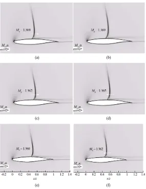
Along with the aerodynamic coefficients, the shock wave is also found to be oscillated with a periodicity in its movement. In Figure 4, the computer numerical Schlieren images (density gradient) of the shock wave at dif-ferent time instants in a shock oscillating cycle are shown. At the beginning of the oscillation at t/T = 1/5 (Figure 4(a)), the shock is located at x/c = 0.40 and Mach number upstream of the shock, Ms is found to be
1.369. The shock wave is strong enough to separate the boundary layer which could be seen in all the images. As the flow moves to the next time instant, at t/T = 1/5 (Figure 4(b)), the shock waves moves downstream to x/c = 0.43. The Mach number upstream of the shock, Ms at this time is 1.362. The direction of shock movement is
x/c
-C
p
0 0.2 0.4 0.6 0.8 1
-1.5 -1 -0.5 0 0.5 1 1.5
[image:4.595.117.516.398.462.2](a) (b)
Figure 3. Unsteady aerodynamic behavior for baseline RAE 2822 airfoil; (a)
Cl and (b) Cd (M∞= 0.729, α = 5˚).
(a) (b)
(c) (d)
(e) (f)
Figure 4. Numerical Schlieren images for transonic flow past baseline RAE 2822 airfoil; (a) t/T = 0/5, (b) t/T = 1/5, (c) t/T = 2/5, (d) t/T = 3/5, (e) t/T = 4/5, (f) t/T = 5/5.
[image:5.595.172.457.256.626.2]shock location is found at 0.43 with Ms = 1.360 (Figure 4(e)). And at t/T = 1 (Figure 4(f)) the shock returns to
its initial position of x/c = 0.40 with the identical Ms as in t/T = 0. In this way, the shock wave oscillates around
the airfoil upper surface and this phenomenon has been confirmed with repeated identical oscillation in a long duration unsteady computation which is allowed in present computation.
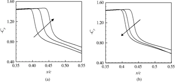
This oscillating behavior of shock wave is further demonstrated in Figure 5 where the distribution of Cp over the airfoil upper surface is shown at different time steps in one time period of shock oscillation. Figure 5(a) shows the downstream movement of the shock wave with increment of time in the first half cycle while Figure 5(b) shows that the shock wave travels upstream and reaches its initial position at the end the second half cycle. This clearly shows the unsteady yet periodic nature of the transonic shock wave oscillation around baseline RAE 2822 supercritical airfoil.
3.3. Airfoil with Shock Control Cavity
Transonic shock wave oscillation as found in baseline RAE 2822 airfoil imposes fluctuating aerodynamic pres-sure and thermal loads on the airfoil which obviously have detrimental consequences of airfoil operation. Thus, the control of transonic oscillation is a must for safe and reliable operation of supercritical airfoil. To control the shock oscillation, an open rectangular cavity is introduced on the top surface of the airfoil around the shock ex-cursion zone. In case of baseline airfoil, the shock oscillates from x/c = 0.40 to x/c = 0.45 which is already been discussed in the previous section. The root mean square (RMS) pressure distribution over the airfoil surface, as plotted in Figure 6, shows that there is significant pressure rise in oscillation at and near the shock wave. How-ever, the variation of pressure distribution upstream of x/c = 0.40 and downstream of x/c = 0.55 is smooth. Thus, a shock control cavity (SCC) is placed over this entire zone that spans from x/c = 0.40 to x/c = 0.55. The shape of the shock control cavity is purely rectangular with length of 15% c. To identify the effect of cavity geometric dimension on the shock oscillation control, three different depths of the cavity, D = 2%, 2.5% and 3% of c are investigated in this study. These configurations will be denoted by cavity-1, cavity-2 and cavity-3, respectively. With the introduction of control cavity, the transonic flow field becomes steady with no shock wave movement around the airfoil upper surface. In addition, the aerodynamic coefficients (lift and drag) also showed non-fluc- tuating behavior in an unsteady computing environment. Schlieren images of the steady flow fields for the con-trol cases are shown in Figure 7. It is seen that in case of airfoil with cavity-1, the shock is concentrated at a particular location and the shock Mach number has been increased compared to that of the baseline airfoil. But in cases of airfoil with cavity-2 and cavity-3 shock Mach numbers are found to be reduced than that of the base-line airfoil. The shock wave structure changes from normal to a λ-shock in these two control cases. The reduc-tion in shock Mach number and the appearance of the λ-shape shock structure are fundamental indications of the reduction of shock strength. Furthermore, the shock position remains fixed over the time for all the three control cases which means the shock oscillation has been disappeared.
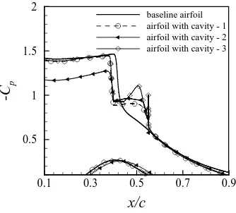
The Cp distributions, shown in Figure 8, over the surfaces of airfoils with cavity are compared with the time- averaged Cp distribution of the baseline airfoil. It is observed that unlike the baseline airfoil, sudden pressure drop is minimized in control cases. The cavity results in a series of isentropic compression waves making the
[image:6.595.162.467.554.696.2](a) (b)
Figure 6. Distribution of Root Mean Square (RMS) of pressure oscillation over airfoil upper surface and cavity location.
(a) (b) (c)
Figure 7. Computer numerical Schlieren images of steady shock for airfoil with (a) cavity- 1, (b) cavity- 2, (c) cavity- 3.
Figure 8. Comparison of pressure distribution for baseline airfoil and airfoil with control cavities.
shock wave weaker. In this study, for the airfoil with cavity-2, the pressure drop is observed to be the least, re-sulting in the largest reduction in shock strength among the three investigated cavity geometries.
Figure 9 shows the time histories of Cd and Cl for the airfoils with shock control cavity. It is clear from the figure that the Cd and Cl for the control cases have became time independent after initial transients. The unsteady behavior which was observed in the baseline airfoil has been no more observed. A comparison of aerodynamic behaviors among the three geometries is listed in Table 3. Though all the modified airfoils stabilize the flow field and hence the shock wave to steady, the lift-to-drag ratio is slightly decreased for the airfoil with cavity-1 and 3 while it shows further improvement in case of airfoil with cavity-2. In terms of drag characteristics, the
x/c
-C
p
0.1 0.3 0.5 0.7 0.9
0.5 1 1.5 2
[image:7.595.136.496.258.410.2] [image:7.595.230.397.447.598.2](a) (b)
Figure 9. Steady behavior of (a) Cland (b) Cd in cases of airfoil with cavity (M∞= 0.729, α = 5˚).
Table 3. Aerodynamic performance of baseline airfoil and airfoil with shock control cavity.
Cases Cl Cd l/d Drag change
Baseline airfoil 0.8868 0.0466 19.03 -
airfoil with cavity - 1 0.8667 0.0456 19.00 −2.14%
airfoil with cavity - 2 0.8675 0.0453 19.15 −2.78%
airfoil with cavity - 3 0.8953 0.0476 18.80 + 2.14 %
airfoil with cavity-2 shows the best results with 2.78% drag reduction compared to baseline airfoil.
4. Conclusion
A numerical computation has been carried out by solving Reynolds Averaged Navier-Stokes (RANS) equations to investigate the transonic shock behavior over a supercritical airfoil RAE 2822 with and without a shock con-trol cavity. The free stream Mach number and angle of attack (AOA) were kept constant at 0.729 and 5˚, respec-tively. The findings from this present study can be summarized as follows:
• Self-excited and self-sustained shock wave oscillation is observed for the baseline RAE 2822 airfoil at the flow conditions under present investigation.
• The aerodynamic characteristics of the baseline airfoil are found to be varying in time with a periodic form. • With the introduction of an open rectangular shock control cavity, the shock wave oscillation has been com-pletely disappeared.
• The presence of cavity changes the shock structure from normal to λ-shock which results in the reduction of shock strength in the flow field.
• This confirms the cavity as a promising approach of passive control for shock wave oscillation around a su-percritical airfoil in transonic flow conditions.
Acknowledgements
The present work has been carried out with computational resource support from Higher Education Quality En-hancement Project (HEQEP), AIF (2nd Round)-Sub-Project CP 2099, UGC, MoE, Government of Bangladesh (Contract No. 28/2012).
References
[1] Tijdeman, H. (1977) Investigation of the Transonic Flow around Oscillating Airfoils. PhD. Thesis, TU Delft, Delft. [2] McDevitt, J.B., Levy, L.L. and Deiwert, G.S. (1976) Transonic Flow about a Thick Circular-Arc Airfoil. AIAA Journal,
14, 603-613. http://dx.doi.org/10.2514/3.61402
[3] Levy, L.L. (1978) Experimental and Computational Steady and Unsteady Transonic Flows about a Thick Airfoil. AIAA
Journal, 16, 564-572. http://dx.doi.org/10.2514/3.60935
t (s) Cl
0.2 0.4 0.6 0.8 1
0.80 0.85 0.90 0.95 1.00
airfoil with cavity - 1 airfoil with cavity - 2 airfoil with cavity - 3
t (s) Cd
0.2 0.4 0.6 0.8 1 0.030
0.040 0.050 0.060
[image:8.595.137.492.276.355.2][4] Alshabu, A. and Olivier, H. (2008) Unsteady Wave Phenomena on a Supercritical Airfoil. AIAA Journal, 46, 2066- 2073. http://dx.doi.org/10.2514/1.35516
[5] Zhao, Z., Ren, X., Gao, C., Xiong, J., Liu, F. and Luo, S. (2013) Experimental Study of Shock Wave Oscillation on SC (2)-0714 Airfoil. Proceedings of the 51st AIAA Aerospace Sciences Meeting, Dallas, 7-10 January 2013, AIAA 2013- 0537. http://dx.doi.org/10.2514/6.2013-537
[6] Qin, N., Zhu, Y. and Shaw, S.T. (2004) Numerical Study of Active Shock Control for Transonic Aerodynamics.
Inter-national Journal of Numerical Methods for Heat & Fluid Flow, 14, 444-466.
http://dx.doi.org/10.1108/09615530410532240
[7] Hasan, A.B.M.T., Matsuo, S., Setoguchi, T. and Islam, A.K.M.S. (2012) Effects of Condensing Moist Air on Shock Induced Oscillation around an Airfoil in Transonic Internal Flows. International Journal of Mechanical Sciences, 54, 249-259. http://dx.doi.org/10.1016/j.ijmecsci.2011.11.004
[8] Stanewsky, E. (2001) Adaptive Wing and Flow Control Technology. Progress in Aerospace Sciences, 37, 583-667. http://dx.doi.org/10.1016/S0376-0421(01)00017-3
[9] Li, J., Lee, C.H., Jia, L. and Li, X. (2009) Numerical Study on Flow Control by Micro-Blowing. Proceedings of the
47th AIAA Aerospace Sciences Meeting, Orlando, 5-8 January 2009, AIAA 2009-779.
http://dx.doi.org/10.2514/6.2009-779
[10] Ashill, P.R., Fulker, J.L. and Shires, J.L. (1992) A Novel Technique for Controlling Shock Strength of Laminar-Flow Airfoil Sections. Proceedings of the 1st European Forum on Laminar Flow Technology, Hamburg, 16-18 March 1992, 175-183.
[11] Hasan, A.B.M.T. and Alam, M. (2014) A Numerical Study on the Control of Self-Excited Shock Induced Oscillation in Transonic Flow around a Supercritical Airfoil. International Journal of Fluid Mechanics Research, 41, 440-459. http://dx.doi.org/10.1615/InterJFluidMechRes.v41.i5.50
[12] Mazaheri, K., Kiani, K.C., Nejati, A., Zeinalpour, M. and Taheri, R. (2015) Optimization and Analysis of Shock Wave/Boundary Layer Interaction for Drag Reduction by Shock Control Bump. Aerospace Science and Technology,
42, 196-208. http://dx.doi.org/10.1016/j.ast.2015.01.007
[13] Bahi, L., Ross, J.M. and Nagamatsu, H.T. (1983) Passive Shock Wave/Boundary Layer Control for Transonic Airfoil Drag Reduction. Proceedings of the 21st Aerospace Sciences Meeting, Reno, 10-13 January 1983, AIAA-83-0137. http://dx.doi.org/10.2514/6.1983-137
[14] McComick, D.C. (1993) Shock/Boundary-Layer Interaction Control with Vortex Generators and Passive Cavity. AIAA
Journal, 31, 91-96. http://dx.doi.org/10.2514/3.11323
[15] Rahman, M.M., Hasan, A.B.M.T., Islam, A.K.M.S., Matsuo, S. and Setoguchi, T. (2015) Computation of Transonic Internal Flow around a Biconvex Airfoil with Cavity. Journal of Mechanical Science and Technology, 29, 2415-2421. http://dx.doi.org/10.1007/s12206-015-0540-0
[16] Smith, A.N., Babinsky, H., Dhanasekaran, P.C., Savil, A.M. and Dawes, W.N. (2003) Computational Investigation of Groove Controlled Shock Wave/Boundary Layer Interaction. Proceedings of the 41st Aerospace Sciences Meeting and
Exhibit, Reno, 6-9 January 2003,AIAA 2003-0446. http://dx.doi.org/10.2514/6.2003-446
[17] Bur, R., Corbel, B. and Delery, J. (1998) Study of Passive Control in a Transonic Shock/Wave Boundary Layer Inte-raction. AIAA Journal, 36, 394-400. http://dx.doi.org/10.2514/2.376
[18] Yagiz, B., Kandil, O., Pehlivanoglu, Y.V. (2012) Drag Minimization Using Passive and Active Flow Control Tech-niques. Aerospace Science and Technology, 17, 21-31. http://dx.doi.org/10.1016/j.ast.2011.03.003
[19] Menter, F.R. (1994) Two-Equation Eddy-Viscosity Turbulence Models for Engineering Applications. AIAA Journal,
32, 1598-1605. http://dx.doi.org/10.2514/3.12149 [20] ANSYS, Inc., Canonsburg. www.ansys.com
[21] Cook, P.H., McDonald, M.A. and Firmin, M.C.P. (1977) Aerofoil RAE 2822: Pressure Distribution and Boundary Layer and Wake Measurements. AGARD AR 138, A6-1-A6-77.
[22] Coakley, T. (1987) Numerical Simulation of Viscous Transonic Airfoil Flows. Proceedings of theAIAA 25th
Aero-space Sciences Meeting, Reno,12-15 January 1987, AIAA-87-0416. http://dx.doi.org/10.2514/6.1987-416
[23] Yu, T., Wang, J.J. and Zhang, P.F. (2011) Numerical Simulation of Gurney Flap on RAE-2822 Supercritical Airfoil.