Pervasive Computing and Its Application to Traffic
Collision and Congestion Control
Rahul Srivastava
MCA Final year StudentABES Engg. College Ghaziabad, India
Kitty Ahuja
Assistant Professor ABES Engg. CollegeGhaziabad, India
ABSTRACT
Pervasive computing means "existing everywhere”. It is the growing trend towards embedding microprocessors in everyday objects so they can communicate information. Due to this, all the embedded and mobile computing devices are becoming more and more pervasive and dynamically adaptive. In this paper we have described how a pervasive computing model helps to achieve dynamic adaptation with the environment and ubiquitously handles the overall environment. This paper sketches a hypothetical pervasive computing scenario, and uses them to identify key capabilities missing from today’s systems. And for so we have demonstrated a pervasive model which can handle various traffic issues such as deadlock prevention and various random cases like car to car collision, sending signals to the vehicles approaching towards the point of collision and to prevent further deadlock problems. In this paper, we have shown previous problems in the era of computing and its solution achieved by this computing technology. The first section of this paper gives introduction to pervasive computing then second section describes the approach overview of this computing technology, third section deals with its layered architecture and fourth concentrates on case study analysis with explanation of hypothetical scenarios fifth, sixth and seventh deals with the proposed work and finally the last section gives the conclusion and references.
Keywords
Pervasive, Ubiquitous, Mobile Computing, Agent
1.
INTRODUCTION
The term 'pervasive' computing was coined and popularized by Mark Weiser in his ground breaking 1991 paper [1] when he envisioned computing and communication environments seamlessly integrated with end users. Previously there were so many problems and issues which were solved with much human intervention but these problems get solved with this new era of computing and will provide the attractive vision of future reality.
It is an idea of making things smarter and interactive systems and revolutionalize, the way human beings interact with the world around them. Everything from a small pen to human body can be embedded with a chip or sensor and behave in response to the environment by storing and providing facility and various data in real time.
In the past, systems that supported self adaptation were rare, confined mostly to domain like telecommunications switches or deep space control software, where taking a system down for upgrades was not an option, and where human intervention was not always feasible. However, in a pervasive computing world more and more systems have this requirement, because they must continue to run with only minimal human oversight, and cope with variable resources as a user moves from one environment to another (bandwidth, server availability etc.), system faults (servers and networks going down, failure of external components, etc.), and changing user priorities (high-fidelity video streams at one moment, low (high-fidelity at another, etc.).
Traditionally there was a pre-defined set up and system self-repair has been handled within the application, and at the code level. A mechanism or a procedure has to be written in response to an action. For example, applications typically use generic mechanisms such as exception handling or timeouts to trigger application-specific responses to an observed fault or system anomaly.
So there is a need to make things pervasive or ubiquitous. An important requirement for pervasive computing systems is the ability to adapt them at runtime to handle such things as user mobility, resource variability, changing user needs, and system faults. There is a need to design the system which is having a global perspective and smart interaction with its environment. Basic themes of pervasive computing are:
• Intelligence • mobile computing • Sensor network technology • Invisibility
2.
APPROACH OVERVIEW
Human attention is specially a scarce source in such environments, since the user is often preoccupied with walking, driving or other real world interactions. In addition, this environment has many challenges including the use of handheld devices with limited network capability and battery power and the presence of diverse and possibly unfamiliar physical space.
purpose there is a system which can define the primary entities in the user’s context such as people, devices, physical space and network. It also provides information about relationship between these entities. For example location based services provide information about people location and physical space.
This field of computing showing a very vast emerging growth in the upcoming generation which can completely changes the human surrounding and capabilities that describe the extent of its functionality. Mobility and ad-hoc networking capabilities are expected to emerge relatively soon. Context awareness and embedment in everyday objects are viewed as pervasive computing definitive and formative characteristics.
3.
LAYERED ARCHITECTURE OF
MODEL
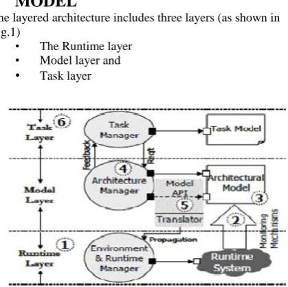
The layered architecture includes three layers (as shown in Fig.1)
• The Runtime layer • Model layer and • Task layer
Figure 1 Layered Architecture of Pervasive Computing [3]
Runtime Layer
The runtime layer is responsible for observing a system’s runtime properties and performing low-level operations to adapt the system. It consists of the system itself, together with its operating environment (networks, processors, I/O devices, communications links, etc.)
Observed runtime information is propagated upwards using a monitoring infrastructure that condenses, filters, and abstracts those observations in order to render that information (2) in architecture-relevant terms
Model Layer
The model layer is responsible for interpreting observed system behavior in terms of higher-level, and more easily analyzed, properties. It forms the centerpiece of the approach, consisting of one or more architectural models of the system (3) Together with respective architecture managers (4) that determine whether a system’s runtime behavior is within the
envelope of acceptable ranges. An architecture manager includes a constraint checker and a repair handler. The former determines when architectural constraints are violated; the latter determines how to adapt the system. Repairs are propagated down to the running system (5).
Task Layer
(6) The task layer is responsible for determining the quality of service requirements for the task(s). A task is a high-level representation of a user’s computational needs, and indicates the action required, as well as the desired performance profile for those actions.
These profiles in turn determine the range of behavior permissible at an architectural level.
The task layer has knowledge of the kind of actions which is to be taken when required and the quality of service (accuracy, response time etc.) requirements for retrieving the information.
This knowledge feeds into the Model Layer, so that relevant analyses can be performed to determine the appropriate configuration at random situation.
The model layer then makes changes through the runtime layer, to the executing system to fulfill those requirements and take supportive actions.
4.
CASE STUDY ANALYSIS
Smith is approaching towards his office in the morning and he chooses a path via a junction named “Cross wood”. It is a junction of four Roads coming from East, West, North and South. Smith is driving a car at a distance of 3 km. before “Cross wood” junction. Suddenly an accident happens at “Cross wood” junction and lot of cars were standing and waiting for their passage but none of them is able to get the pass. Then traffic management automatic system at “Cross wood” analyses the environment and based on analysis generates an alert signal which is sent to all the vehicles approaching towards “Cross wood”. The automatic system not only sends alert signal but also specifies some alternative path and suggest a list of available paths, the driver can choose any one of them according to their norms. Therefore Smith chooses a new way to reach his destination on time without any hindrance. Signals are passed through signaling system which conveys the message to the vehicles in the way. And thus the system helps in reducing the deadlock at junction point.
This model alarms people about the accident that can be understood by understanding the following:
• Firstly the communication can takes place between the vehicles and the automatic system and between the cars.
[image:2.595.61.271.243.452.2]5.
PROPOSED MODEL
[image:3.595.55.280.82.246.2]In our proposed concept “Warning Signals” can be generated by the “traffic automated system” which is transmitted securely to the vehicles which can cause any kind of danger. When the signal received by the vehicle the “car system” automatically applies brake and the “Automatic brake” system gets activated which stops the vehicle at the position when the automated tool senses the vehicles position moving towards each other it sends warning signal when the car is at some distance say (less than 20 meter). It measures the distance between the cars through sensors e.g. capacitive displacement sensor. The Figure. 3 shows the pictorial representation of the proposed model.
Figure 3 Proposed Model
Working Procedure
The tool will work on the principle of the deflection caused due to the change in the capacitance value between the cars and this deflection will be caused when the two cars approach towards each other also when the cars are about to crash. Here the “capacitive sensor” is used to measure the distance between the cars.
When the distance ”d” in capacitive displacement sensor becomes small due to capacitance increase and when this distance between the cars become small the tool starts working to sense its behavior, it then sends signal to cars. It uses some training data to perform the task. Therefore, the car will either slow down or apply automatic break when the distance is too less say (2 meter) or some predefined limit.
6.
WORKING MODULE ALGORITHM
The following is the algorithm which describes how this tool works.
Input: Distance “DB_car” (distance between the car) Output: Warning signal, automatic break in the car with some parameters such as TimeLeft, Speed and distance between the approaching cars.
ALGORITHM Accident_Saviour() {
For each car perform the following steps: While (DB_car <= DIST_THRESH) do
Calculate next distance DB_car between cars.
Calculate RelativeSpeed (SP_car) =Distance (DB_car)/time (T_car).
If distance DB_car < DIST_THRESH and SP_car > SP_THRESH and (T_car <= PEAK_TIME)
Then WSignal=”this is a critical speed please slow down your speed now”;
R_Factor=High;
send critical situation details-Automatic Break Signal, SP_car, R_Factor(risk factor), T_car(time).
Else
R_Factor=Medium;
Wsignal=”Travel with recommended speed for safe journey”;
Send warning signal (WSignal), R_Factor (risk factor). Out of coverage area, ignore and do nothing.
[image:3.595.54.278.420.588.2]Figure 4 Decision Tree Diagram
Table 1 Training Data for Automated Tool
Geometrical Scenario of Cars with Tool
Case 1
Case 2
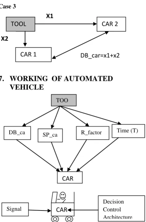
Case 3
7.
WORKING OF AUTOMATED
VEHICLE
The tool is having the same architecture as above mentioned three layers:
The signals received by the smart tool in the car will be interpreted or acquisition by the Runtime layer and gets propagated by its upper layers Model layer and Task layer. Let’s have a look how it works.
7.1
Working Procedure
Based on the above algorithm Accident_Saviour() some parameters will be transmitted to the tool end (i.e. device in the car).On receiving the parameters the first step is to evaluate the parameters, therefore on the basis of the parameters received the following are the cases that may arise.
Case 1: If R_Factor (risk factor) is “High” then next step is to check the time limit (minimum time in which accident can be saved) , this will be checked first in order to ensure that accident or collision can be saved in defined time or chances of applying the break by driver. If the case above is not then over all control is in the hand of automated tool in the car to apply further necessary action such as application of automatic break.
Case 2: If R_Factor is “Medium” then infrom the driver to take control of the car speed also display various parameters like display Wsignal (warning signal), DB_car (distance between two car), R_Factor(risk factor), T_car(time to save the collision) and message to slow down speed of car.
Case 3: If R_Factor is low then simply ignore the message and remains in its state.
Distance (meters)
Speed(km/hour )
Action Risk
factor(R_Factor )
D>DIST_ THRESH
SP_car>SP_T HRESH
Warning! Medium
D< DIST_TH RESH
SP_car>SP_T HRESH
Warning + Automatic break
High
D< DIST_TH RESH
SP_car<SP_T HRESH
Warning Normal
D> DIST_TH RESH
SP_car<SP_T HRESH
Warning Normal
No T_car,DB_car,
SP_car
DB_car,
SPcar, T_car
tDB_car,
SPcar,
T_carTT
DB_car,
SPcar,
T_carT_carT_
carT_carT_ca
rT_carT_carT
_carT_carT_c
arT_carT_car
T_caraaa
CAR DB_car < DIST_THRESH
yes
No
SP_car > SP_THRESH
ar >
SP_THRESH
SP_THRESH
Ignore and do nothing
yes
Send warning signal SP_car, R_Factor=Medi um
Send Critical situation details
SP_car, R_Factor=High
CAR 1
CAR 2
TOOL
DB_car
X1
X2
TOOL
CAR 1
CAR 2
X1
X2
TOOL
CAR 2
DB_car=x1+x2
CAR 1
X1
X2
TOO L
R_factor SP_ca
r DB_ca
r
Time (T)
CAR
Signal
CAR
Car_Saviour(WSignal, R_Factor, T_car, DB_car) {
1. Check the parameters Wsignal, R_Factor, T_car, DB_car
2. If(R_Factor=High) 3. Do check
4. If (T_car>=Time_Limit)
5. Extract Wsignal message and display DB_car on screen or notification to apply break.
6. Else
7. Send automatic break signal to internal devices and working break applied results time+details 8. Else if(R_Factor=Medium)
9. Display Wsignal, DB_car, and message to apply break or slow down the speed of car.
10. Else
11. Ignore the signal and remains in the same state. }
8.
CONCLUSION
Pervasive computing has proven to be amazing source of challenging problems in computer system for many years to come and in the current scenario, one of the special area is the area of traffic collision and congestion control which requires proper communication between cars and traffic automated tool for managing traffic and prevent accidents which we have presented in our paper, but when it comes to communication between human and computer there is requirements of software agents with high level pro-activity behavior like human, capabilities from these areas also needs to be integrated with systems as discussed in this paper. As our life is moving more towards miniaturization and 21st century will be moving more likely towards hardware progress and in research areas like sensors and automated devices with special pro-activity and context sensing capabilities is helping to achieve the objective.
The present scenario of traffic problems are still faced by people in their day-to-day life. So pervasive computing offers new beginning for the adventurous and the restless-a rich open space where the rules are yet to be written and borders yet to be drawn[5].
9.
ACKNOWLEDGMENT
We are thankful to Prof. Jagdish Singh for inspiring and guiding us to write this paper. We are grateful to dozens of others whose names are given among the references of this paper, for influencing our understanding and views of pervasive computing.
10.
REFERENCES
[1] Weiser M., The Computer for the 21st Century, Scientific American, September, 1991.
[2] Weiser, M, Brown, J.S. The Coming Age of Calm Technology. In Denning, P.J., Metcalfe, R.M. (editors), Beyond Calculation: The Next Fifty Years of Computing. Copernicus, 1998.
[3] Shang-Wen Cheng, David Garlan, Bradley Schmerl, João
[4] 2006 Bundesamt für Sicherheit in der Informationstechnik –BSI Godesberger Allee 185-189, 53175 Bonn, Germany and SecuMedia Verlags-GmbH .Page73 Postfach 1234 55205 Ingelheim, Germany Tel. 06725/93040 Fax. 06725/5994 E-Mail: [email protected]
[5] M. Satyanarayanan-Pervasive Computing Vision and Challenges. School of Computer Science, Carnegie Mellon University.
[6] Abowd, G., Allen. and Garlan, D. Using Style to Understand Descriptions of Software Architectures. In Proceedings of SIGSOFT’93: Foundations of Software Engineering, December1993.
[7] Abowd, G., Burmitt, B., and Shafer, S. (Eds). Ubicomp 2001: Ubiquitous Computing - Third International Conference Atlanta, Georgia, USA, September 30 - October 2, 2001 Proceedings. Lecture Notes in Computer Science 2201, Springer, October 2001
[8] David Garlan, Daniel Siewiorek, Asim Smailagic, and Peter Steenkiste. Project Aura: Towards Distraction-Free Pervasive Computing. IEEE Pervasive Computing, 1(2):22–31, April-June 2002.
[9] INTERNATIONAL CIVIL AVIATION
ORGANIZATION, Biometrics Deployment of Machine Readable Travel Documents, Technical Report, Version 2.0, 21/05/2004.
[10]INOUE, H., OSAWA, S. et al., Dedicated Short-Range Communications (DSRC) for AHS Services, Proceedings 2004 IEEE Intelligent Vehicles Symposium, June 14-17, 2004, Parma, Italy, pp-369-374.
[11]Technology and Society Magazine, Volume 24, Issue 1, pp. 24 - 33, 2005
[12]Michael H. Coen, "Design Principles for Intelligent Environments", Proceedings of the fifteenth national/tenth conference on Artificial intelligence/Innovative applications of artificial intelligence, Madison, Wisconsin, United States; pp. 547 - 554, 1998
[13]Guy Dewsbury, "The Social and Psychological Aspects of Smart Home Technology within the Care Sector", Journal of New Technology In The Human Services, Volume 14 , Issue 1-2 , pp. 9-18 , 2001
[14]Paul Dourish and Genevieve Bell, "Yesterday’s tomorrows: notes on ubiquitous computing’s dominant vision", Personal and Ubiquitous Computing, Volume 11, Issue 2, pp. 133 - 143, 2007
[15]Yitao Duan and John F. Canny, "Protecting user data in ubiquitous computing: Towards trustworthy environments", Privacy Enhancing Technologies, Volume 3424, pp. 167 - 185, 2005
![Figure 2 Traffic Management Automatic System [4]](https://thumb-us.123doks.com/thumbv2/123dok_us/8034858.769904/3.595.54.278.420.588/figure-traffic-management-automatic-system.webp)