STRUCTURAL BEHAVIOUR OF BEAM WITH HDPE PLASTIC BALLS
SUBJECTED TO FLEXURE LOAD
Noridah Mohamad1, W.I.Goh2*, A.A.A. Samad3, A. Lockman4, Josef Hadipramana5
1,2,3,4,5 Department of Structure and Material Engineering, Faculty of Civil and Environmental Engineering
Universiti Tun Hussein Onn Malaysia, Parit Raja, 86400 Batu Pahat, Johor, Malaysia
*Corresponding author: [email protected]
Abstract
This paper presents the structural behavior of reinforced concrete beam embedded with high density polyethylene balls (HDPE) subjected to flexural load. The HDPE balls with 180 mm diameter were embedded to create the spherical voids in the beam which lead to reduction in its self-weight. Two beam specimens with HDPE balls (RC-HDPE) and one solid beam (RC-S) with dimension 250 mm x 300 mm x 1100 mm were cast and tested until failure. The results are analysed in the context of its ultimate load, load-deflection profile, and crack pattern and failure mode. It was found that the ultimate load of RC-HDPE was reduced by 32% compared to RC-S beam while the maximum deflection at its mid span was increased by 4%. However, RC-HDPE is noticed to be more ductile compared to RC-S beam. Both types of beams experienced flexure cracks and diagonal tension cracks before failure.
Keywords: HDPE plastic balls, self-weight, structural behavior, flexural load, deflection
1.0 Introduction
Concrete is the most consumed material for construction industries. However, the concrete weight penalty has become its weakness. This has created interest among researchers to look at possible ways to overcome this shortcoming by altering the mixture of material used in concrete casting. The usage of lightweight materials in construction has become increasingly popular due to huge available of such materials either artificially made or from industrial and organic waste. Among the lightweight materials that have been used as materials in construction are extruded polystyrene, foamed concrete, lightweight aggregate, plastic bottle, aluminum, and even products from plantation such as peanut shells and rice husk. Studies have proven that certain materials mentioned above are viable to be used as building materials. For example, polystyrene has been used as the insulation material enclosed between two outer skin layers in walls [1,2,3]. Recycled aggregate is proven to have lower density and mechanical properties slightly lower or similar to natural aggregate depending on the percentage it is used as replacement and also the type of curing [4, 5]. Meanwhile, alumina is proven to be viable as both skins and core layer in sandwich panel system [6,7].
One of the solutions to reduce the weight of the concrete is by using reinforced concrete with hollow plastic balls such as high-density polyethylene balls or HDPE. HDPE is created from ethylene through catalytic process. This material is higher in density and strength compared to low density polyethylene. HDPE is also good in impact resistance, light weight, low moisture absorption, and high tensile strength. HDPE can be recycled where it has economically advantages due to lower costs of removing the waste and thereduction of pollution and contamination. This type of polymer wastes is suitable for non-structural use and more cost effective compared to normal concrete [8].
3.0 Materials and Methods
Total number of three (3) beam specimens were cast in this study; two specimens with HPDE hollow plastic ball and one specimen without the plastic ball which function as the control specimen. The proportion for the materials used to cast the concrete beam is presented in Table 1. The concrete’s strength targeted is 30 MPa with 2400 kg/m³ density. The proportion of these materials were measured by weight. Concrete cubes and cylinders were also cast and tested to determine the concrete’s compressive and tensile strength.
Table 1: Mixture of concrete materials
Conrete Grade (MPa) Cement Content (kg) Fine aggregates (kg) Coarse aggregates (kg) Maximum w/c ratio
30 29 57 113 0.5
The beam specimens were reinforced by the main bar and stirrups. The dimension of the specimens is 250 mm width x 300 mm depth x 1100 mm length. High tensilesteel reinforcement bar of 12 mm diameter was used as the main reinforcement at top and bottom of the beam. Meanwhile, low tensile strength steel with 6 mm diameter was used as the stirrup along the span of the beam. HDPE plastic balls with diameter 180 mm are placed in the beam to create the hollow section.
3.1 Fabrication Process
The fabrication process includes the preparation of formworks, mixing the concrete, placing the reinforcement and stirrup in the concrete and finally pouring the concrete. The formwork is made of plywood as shown in Figure 1. The process started with placing a few concrete cover blocks to make sure the steel reinforcement will be fixed in the formworks. The plastic balls and steel reinforcement were then placed in the formwork. Sufficient spacing with length of 180 mm was used to make sure the plastic balls can fit in between the stirrups. Steel wire was used to tie the stirrups to make sure the plastic balls will not float during the casting process. Figure 2 shows the arrangement of plastic balls in the steel reinforcement. The details of the dimension are as shown in Figure 3 and Figure 4 for its layout design and cross-section design, respectively.
Figure 1: Formwork Figure 2: arrangement of plastic balls in the steel reinforcement
Figure 3: Layout design for reinforced concrete beam with plastic balls
Figure 4: Cross section design for concrete beam with plastic balls
3.2 Test Set-up
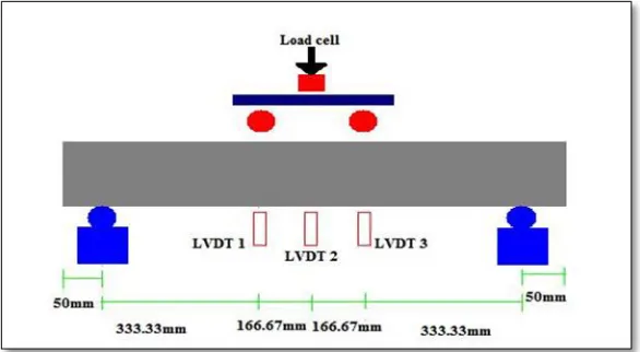
Four point bending test was carried out to study the behaviour of beam with HDPE plastic balls. In this experiment, reinforced concrete beams with plastic balls and the reinforced concrete solid beam as controlled specimen were tested under four point bending test to compare the behaviour obtained by both beams. This test required a load cell to impose the applied load on the beam and Linear Voltan Digital Transducer (LVDT ) to measure the deflection of the specimen. Three LVDT were placed at various locations along the span of the beam as shown in Figure 5 and
300mm
mmmm mm
2T12 1100 mm
100mm 100mm
48 mm
48 mm
250 mm
T12 Y6
50 mm
25 mm
[image:3.612.206.434.417.571.2]Figure 5: Schematic diagram of reinforced concrete beam tested by four point bending test.
Figure 6: Reinforced concrete beam specimen were ready for testing
4.0 Results and Discussions
4.1 Mechanical Properties of Concrete
[image:4.612.158.448.347.522.2]Figure 7: Compressive Strength of concrete
[image:5.612.114.501.362.432.2]4.1.2 Split Tensile Strength. From the split cylindrical tensile strength test conducted, the average value results for tensile strength of the concrete at 28 days is 2.78 MPa. Table 1 shows the results recorded for both cylinder specimens
Table 1: Split Tensile Strength of concrete
Specimen Grade Age Load (kN) Strength (MPa)
C1 C30 28 days 203.04 2.89
C2 C30 28 days 195.11 2.67
Average stength (MPa) 2.78
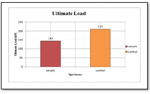
4.2 Ultimate Load. From the results recorded, the average ultimate load of reinforced concrete beam with plastic balls has reached 143kN while the ultimate load of controlled specimen has reached 210kN before failure. The different in percentage for both specimens is almost 32%. The beam with HDPE plastic balls failed at 32% lower load compared to the control specimen.
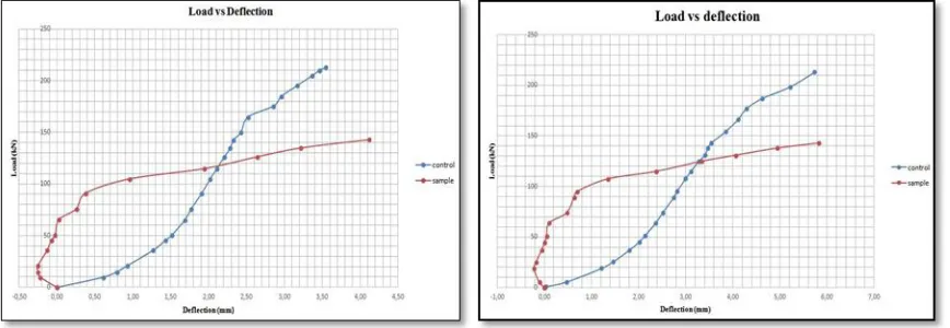
[image:5.612.184.426.516.669.2]Figure 8: Load-Deflection at the mid-span of reinforced concrete beam specimens
Figure 9: Load-Deflection at the (a) left and (b) right point load of reinforced concrete beam specimens
[image:6.612.90.524.365.515.2]Figure 10: (a) The crack patterns of reinforced concrete with plastic balls (b)The crack patterns of reinforced concrete solid beam
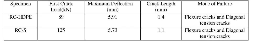
[image:7.612.106.508.73.216.2]As for the controlled specimen, the first crack took a longer time to occur and only appeared when the load reached 125 kN with crack length recorded at 1.1 mm. The crack propagated as tension crack at the bottom part of the beam. Compared to the reinforced concrete beam with plastic balls, the flexural cracks for reinforced concrete solid beam were recorded to occur at more locations along the beam’s span. This is due to the larger load it took before failure. Table 2 presents the values of first crack load, maximum deflection at mid-span, crack length, and mode of failure for both RC-HDPE and RC-S beams. All the values recorded for RC-HDPE beam are the average values recorded from two tested RC-HDPE specimens.
Table 2: Values of first crack load, maximum deflection at mid-span, and the crack length of RC-HDPE
Specimen First Crack Load(kN)
Maximum Deflection (mm)
Crack Length (mm)
Mode of Failure
RC-HDPE 89 5.91 1.4 Flexure cracks and Diagonal
tension cracks
RC-S 125 5.73 1.1 Flexure cracks and Diagonal
tension cracks
5.0 Conclusions
The ultimate load and first crack load recorded for RC-HDPE are lower compared to the RC-S beam. Maximum deflection and crack length of RC-HDPE beam is slightly higher compared to RC-S beam. However, from the load-deflection profile, it is noticed that RC-HDPE beam is more ductile compares to RC-S beam where it took longer time to fail after the first crack load.
Acknowledgement
[image:7.612.59.542.402.481.2]Innovative Infrastructures, Seoul, Korea. 2012.
[5] Sato, R., Maruyama, I., Sogabe, T., & Sogo, M. “Flexural Behavior of Reinforced Recycled Concrete Beams.” Journal of Advanced Concrete Technology, 5, 1, 43–61. 2007.
[6] M. Kampner, R. M. Deacon, A. R. Marder. Failure analysis of an aluminum sandwich panel skin from the space shuttle Columbia. Journal of Failure Analysis and Prevention. Volume 6, Issue 1, 46-50. 2006
[7] K.Kantha Rao, K. Jayathirtha Rao, A.G.Sarwade, B.Madhava Varma. Bending Behavior of Aluminum Honey Comb Sandwich Panels . International Journal of Engineering and Advanced Technology (IJEAT) ISSN: 2249 – 8958, Volume-1, Issue-4, 2012.
[8] M.Mustafa Al Bakri, S. Mohammad Tamizi, A. R. Rafiza, Y. Zarina, Investigation Of HDPEPlastic Waste Aggregate On The Properties Of Concrete. Journal of Asian Scientific Research, 1(7), pp. 340-345, 2011
[9] Saifee Bhagat , Dr. K. B. Parikh . Comparative Study of Voided Flat Plate Slab and Solid Flat Plate Slab . Internatinal Journal of Innovative Reasearsch and Development. Vol. 3, Issue 3. 2014.