THE EXPERIMENTAL STUDY AND NUMERICAL SIMULATION OF FALLING LIQUID FILM FLOW ON HORIZONTAL TUBES
IBNU ANAS BIN HASSAN
A thesis submitted in
fulfillment the requirement for the award of the Degree of Master of Mechanical Engineering by research
Faculty of Mechanical and Manufacturing Engineering Universiti Tun Hussien Onn Malaysia
iii
I wish to dedicate especially to
my beloved family , supervisor, co-supervisor, colleagues and those who have guided and inspired me throughout my journey of education.
iv
ACKNOWLEDGEMENT
Bismillahirrahmanirrahim, In the name of Allah, the Most Gracious and the Most Merciful. All praise and glory to Almighty Allah who gave me courage and patience to carry out this research and successfully completing my master’s thesis.
The special thanks to my helpful supervisor, Dr. Azmahani Sadikin and co supervisor, Dr. Norasikin Mat Isa. Also, many thanks to internal examiner, Prof. Madya Dr. Nor Zelawati Binti Asmuin, external examiner, Dr. Fatimah Al-Zahrah Binti Mohd Sa'at, Chairperson, Dr. Shahrul Azmir Bin Osman, Chairperson's Assistant, and Dr. Mohd Faizal Bin Mohideen Batcha for their attention, cooperation, comments and constructive criticism. All cooperation are extremely useful for progression and smoothness of my research.
I extend my acknowledgement and heartfelt love to my mother and family members. I am also in indebted to my colleagues Azlizul, Arena Cipta for their patience and understanding. All the experiences, learning and hands on during the program would be nothing without the enthusiasm and imagination from these people.
Finally, I would like express my unrestrained appreciation to Universiti Tun Hussein Onn for supporting this research and providing me with necessary infrastructure and excellent research environment.
v
ABSTRACT
vi
ABSTRAK
vii
CONTENTS
TITLE i
DECLARATION ii
DEDICATION iii
ACKNOWLEDGEMENT iv
ABSTRACT ABSTRAK
v vi
CONTENTS vii
LIST OF TABLES xiii
LIST OF FIGURES xiv
LIST OF SYMBOLS xxiv
LIST OF ABBREVIATIONS xxvii
LIST OF APPENDICES xxviii
CHAPTER 1 INTRODUCTION 1
1.1 Introduction 1.2 Problem Statement 1.3 Objectives of Study 1.4 Scopes of Study 1.5 Dissertation Overview
1 2 2 3 4
CHAPTER 2 LITERATURE REVIEW 5
2.1 Introduction to Falling Liquid Film 2.1.1 Falling Film Evaporator
2.2 Characteristics of Falling Liquids Film on Horizontal Tube
2.2.1 Spray density, ΓL of Falling Film on Horizontal Tube
5 6
12
viii 2.2.2 Working Fluids of Horizontal Falling Film
2.2.3 Dimensions and Material Used in Horizontal Falling Film
2.2.4 Water Boiling Point during MEHT Operation
2.2.5 Ideal Gas Equation for Environmental Air
2.2.6 Archimedes Number for Falling Film Thickness
2.2.7 Humidity of Environmental Air
2.2.8 Reynolds Number of Falling Liquid Film 2.2.9 Environmental Heat Transfer on
Horizontal Falling Film
2.2.10 The Film Thickness on Tube Surface 2.2.11 Numerical Simulation of Falling Liquid
Film
2.3 Critical Review of Previous Studies
16 17 18 19 20 20 21 24 40 49 53 CHAPTER 3 DESIGN AND INSTALLATION OF TEST
FACILITY 56
3.1 Research Methodology
3.2 Introduction to Test Facility of Falling Film 3.3 Design Consideration for Test Facility of Falling
Film
3.4 General Layout for Test Facility of Falling Film 3.5 Detail Description of Test Facility Components
3.5.1 Test Section of Falling Film
3.5.1.1 Material and Tubes Size for Test Facility of Falling Film
3.5.1.2 Spray Distributor for Test Facility of Falling Film
3.5.2 Water Pump for Test Facility of Falling Film
3.5.3 Hose for Water Flow in Test Facility of
ix
Falling Film 63
3.6 Instrumentation and Calibration of Test Facility 3.7 Air Flow Meter and Humidity Apparatus 3.8 Fluids Properties of Falling Film
3.9 Rotameter and Manual Control Valve 3.9.1 Water Flow Rate Measurement for
Horizontal Falling Film
3.9.2 Water Flow Rate Per Unit Length 3.10 Digital Electronic Thermometer
3.11 Thermocouples for DAQ System 3.12 Test Facility Set-up before Experiment
3.12.1 Establishing Sheet Flow Pattern 3.12.2 Flow Pattern Commissioning Tests 3.13 Data Acquisition System
3.13.1 Calibration of DAQ Temperature 3.13.2 Recording Temperatures Data in
Experiment
3.13.3 Extracting and Analyzing Test Data 3.14 Sources of Error in Experiment of Falling Film 3.15 Experimental Standard Operating Procedures
(SOP) and Conditions
64 65 66 67 68 69 70 71 73 74 74 75 78 81 81 82 84 CHAPTER 4 COMPUTATIONAL MODELLING OF WATER
FALLING FILM : TEMPERATURE DIFFERENT &
FILM THICKNESS 86
4.1 Physical and Properties of Numerical Model 4.1.1 Physical of CFD Model for Falling Film
Simulation
4.1.2 Operating Parameters
4.1.3 Fluids Properties for Falling Film Simulation
4.2 Numerical Methodology of Falling Film
4.2.1 Geometry Model - Design Modeler 14.0 4.2.2 Mesh Setup - ANSYS Meshing 14.0
x 4.2.3 Grid Independences Test for CFD Model
4.2.3.1 Grid Independences Test for Temperature Variation
4.2.3.2 Grid Independences Test for Film Thickness
4.2.4 Simulation Setup 4.2.4.1 Analysis Solver 4.2.4.2 Boundary Conditions 4.2.4.3 Solution Methods 4.2.4.4 Solution Controls 4.2.4.5 Initialization Solution 4.3 Analysis of Simulation Results
4.3.1 Measurement Techniques in CFD-Post 4.3.1.1 Positioning of Measurement Lines 4.3.1.2 Average Film Thickness
92 93 94 94 95 97 104 107 107 108 108 110 112
CHAPTER 5 RESULTS AND DISCUSSIONS 113
5.1 Experimental Results of Horizontal Falling Film 5.1.1 Flow Patterns on Horizontal Falling Film 5.1.1.1 Sheet Flow Pattern on Horizontal Falling
Film
5.1.1.2 Column Flow Pattern on Horizontal Falling Film
5.1.1.3 Droplet Flow Pattern on Horizontal Falling Film
5.1.2 Temperature Measurement within Horizontal Falling Film
5.1.2.1 Temperature Measurement for Intertube Spacing of 8 mm
5.1.2.2 Temperature Measurement for Intertube Spacing of 28mm
5.1.2.3 Temperature Measurement for Intertube Spacing of 47mm
5.1.2.4 Temperature Measurement for Intertube
xi Spacing of 133mm
5.1.3 The Cooling Heat Transfer Coefficient Outside Horizontal Falling Film
5.2 The Results of Numerical Simulation for Horizontal Falling Film
5.2.1 Velocity Contour of Fluids Flow
5.2.2 Pressure and Temperature of Fluids Flow 5.2.3 Development of Falling Liquid Film
Profile
5.2.4 Numerical Simulation for Temperature Variations within Horizontal Falling Film 5.2.4.1 Numerical Simulation for Temperature
Variations within Intertube Spacing of 8mm
5.2.4.2 Numerical Simulation for Temperature Variations within Intertube Spacing of 28mm
5.2.4.3 Numerical Simulation for Temperature Variations within Intertube Spacing of 47mm
5.2.5 Numerical Simulation of Film Thickness for 3 Dimensional Models
5.2.5.1 Numerical Simulation of Film Thickness for Intertube Spacing of 10 mm
5.2.5.2 Numerical Simulation of Film Thickness for Intertube Spacing of 20 mm
5.2.5.3 Numerical Simulation of Film Thickness for Intertube Spacing of 30 mm
5.2.5.4 Numerical Simulation of Film Thickness for Intertube Spacing of 40 mm
xii
CHAPTER 6 CONCLUSION AND RECOMMENDATIONS 184
6.1 Conclusion
6.2 Recommendations
184 185
REFERENCES 186
LIST OF CONFERENCES 192
APPENDIX A
Defining Fluids Properties
193 193 APPENDIX B
The Cooling Heat Transfer of Horizontal Falling Film
200 200 APPENDIX C
Procedure in Setting Up NI-DAQmx Software
202 202 APPENDIX D
The Coordinate Points in Locating Measurement Lines for CFD-Post
212
212
INDEX 214
xiii
LIST OF TABLES
2.1 Operational data of two MED with different number of
effects 17
2.2 Range ofRe no.corresponding to flow patterns 21 2.3 Result comparison between Simulation and Experiment 50 3.1 Properties of Water and Air at Five Different States 67 3.2 The accuracy of temperature measurement is depending
on temperature range 70
3.3 Four location points of thermocouples 72
4.1 Properties of falling film at three different states 88
4.2 Fluent Simulation Settings 106
4.3 Water volume fraction in a single measurement line 109 4.4 Coordinate points to locate measurement lines in
CFD-Post 110
5.1 Comparison results for all flow patterns 121
xiv
LIST OF FIGURES
2.1 Water falling film flowing over horizontal tubes 4 2.2 General classification of falling film evaporator 6 2.3 Configuration of horizontal falling film evaporator 8
2.4 Schematic diagram of MED-TVC with 2 effects 9
2.5 Schematic diagram of MED-MVC with simplified
design 10
2.6 Schematic diagram of MED-MVC with two effects 10 2.7 Ammonia-water chiller for air conditioning and
refrigeration system 11
2.8 Γ L remains constant regardless of tube length 13
2.9 Two cases of different tube length 14
2.10 Variation of film thickness between seawater and
pure water 16
2.11 Schematic of three flow modes a) droplet mode,
b) column or jet mode and c) sheet mode 20
2.12 Heat and mass transfer processes associated with
horizontal falling film 23
2.13 Effect of feeder height on heat transfer coefficient
for multiple flow rates 24
2.14 Effect of diameterdand heat transfer coefficients,
hheat on falling liquid film 25
2.15 Experimental set-up of Hoffmannet al.(1996) 26 2.16 Temperature variations along 24 horizontal tubes in
stages 26
2.17 Variation of liquid film and cooling water
xv 2.18 The experimental set-up of Hani (2013) a) Water
falling film system b) Parallel arrangement 28
2.19 Series arrangement 28
2.20 Comparison of the coolant temperature variation
between series and parallel arrangements 29
2.21 The physical model of Gonget al.(2014) 29
Temperatures measurement withinthree directions
of flows 31
2.22 Temperatures measurement withinthree directions
of flows 30
2.23 The variation ofΔT, along the tube column direction
under different falling film flow rates 30
2.24 The experimental set-up of Liuet al.(2014) 31 2.25 Measuring points are located at the front and back
ends of the tube bundle 31
2.26 Effect of condensed water and spray density on
pressure different 32
2.27 Effect of condensed water and spray density on
temperature different 32
2.28 Effect of the tube row in computation data 33
2.29 The temperature distribution across falling-film
tubes bundle 33
2.30 Seven horizontal in-line test tubes bank
configuration in test section 34
2.31 Temperature distribution across tubes bundle 34 2.32 Measuring points along tube to measure the
temperature profile of the water flowing inside 35
2.33 Water temperature profile 36
2.34 Experimental set-up of set-up of Zhenet al.(2001) 36 2.35 Schematic of six thermocouples positions on test
tube 37
2.36 Temperature difference corresponding to heat wall
xvi 2.37 Experimental set-up of Yang & Shen (2008) 38 2.38 Experimental set-up of Yang & Shen (2008) a)
Water falling film system b) Schematic of six
thermocouples positions on test tube 38
Variation of heat flux with heat transfer temperature
differences 38
2.39 Water falling film system of Armbruster & Mitrovic
(1998) 39
2.40 Water temperature different between tubes versus
falling film flow rates 40
2.41 Falling film thickness around horizontal tube 41 2.42 Effects of film flow rate on the heat transfer
coefficient 42
2.43 Variation in film thickness with circumferential
angles 44
2.44 Variation of film thickness at different intertube
spacings 44
2.45 Effect of intertube spacing,S–d, on film thickness,
δ 45
2.46 Effect of outside diameter and film flow rate on the
thickness of a liquid film 46
2.47 Effect of flow rates on film thickness distributions
outside the tube 46
2.48 Effect of tube diameter on film thickness along
circumferential direction 47
2.49 Comparison with previous results 47
2.50 Model: SI-F Series Micro-head Spectral-interference
Laser Displacement Meter 48
2.51 Technical data of model: SI-F Series 49
2.52 Schematic of a triangular configuration of
3-dimensional CFD model 50
2.53 Three types of 2-dimensional CFD model with
xvii 2.54 CFD model with three cylinders on half-symmetry
of numerical domain 51
2.55 Graph of film thickness of water falling on a circular
horizontal tube 52
2.56 Results comparison by Qiuet al.,(2015) 52
2.57 Comparison with previous results 53
3.1 Methodology Flow Chart 57
3.2 Design of test facility in research 58
3.3 Test facility layout of water falling film 59
3.4 Test Section 60
3.5 Internal parts of test section 61
3.6 Stainless steel tube with diameter of 19.05mm 62 3.7 Distributor layout suggested by Armbruster &
Mitrovic (1998) 62
3.8 Water pump for Test Facility of Falling Film 63 3.9 Data acquisition system and other instrumentation
on test facility 64
3.10 Digital air flow meter and humidity apparatus 66 3.11 Acrylic flowmeter in Test Facility shows a)
Rotameter layout and b) There are 2 types of units
available 68
3.12 66 spray holes equal to 0.195 m in length 69
3.13 Digital thermometer for measuring water
temperature 70
3.14 k-typethermocouples based onIECstandards color
codes 71
3.15 Four pairs of thermocouples 72
3.16 Temperature measuring points 72
3.17 Clogged holes prevent water from spraying out
a) Before cleaning and b) After cleaning 73 3.18 Schematic diagram of data acquisition system
xviii 3.19 Data acquisition unit consists of modules, USB
chassis, power and data transfer cables 76
3.20 NI DAQ set-up flow diagram 77
3.21 DAQ device and digital electronic thermometer a) All instruments in test facility and b) Identify
temperature deviation between 2 different probes 78 3.22 Temperature commissioning tests a) Four
temperatures lines b) Digital electronic
thermometer 79
3.23 Thermocouples positions a) Side view and b) Front
view 79
3.24 Comparison of temperature lines a) White line graph
supposed to be the upper b) Normal running 80 3.25 White line deviated significantly from other lines 80
3.26 DAQ visual interface during test run 81
3.27 Unsteadiness due to formation of bubbles 82
3.28 The steadiness formation of sheet flow pattern 83 3.29 Instantaneous disruption of sheet flow structure by
the presence of air flow and water flow disturbance 83 4.1 The features of CFD model in test section for a)
Technical terminology and b) Domain of fluids
region 87
4.2 CFD models with difference intertube spacing,S -d
for a) 40 mm b) 30 mm and c) 10 mm 89
4.3 CFD model designed in ANSYS Design Modeler for
a) 2D drawing view and b) 3D solid 90
4.4 Mesh refinement on CFD model for
a) 2D view and b) 3D view 91
4.5 Boundary conditions on CFD model for 2D view
and b) 3D view 91
4.6 Structured mesh refinement along left side surfaces 92
4.7 Grid independent solution for 28 mm 93
xix
4.9 Grid independent solution for 20 mm 94
4.10 Grid independent solution for 30 mm 95
4.11 Grid independent solution for 40 mm 95
4.12 Ratio of sheet length over CFD model width 97
4.13 Spray holes with diameter,d= 0.9 mm ≈ 1 mm in
diameter 100
4.14 The bottom side of falling film 100
4.15 The length of lbottom 101
4.16 The half of falling film is considered as mhalf 102
4.17 The residual levels showed convergence has been
reached in this analysis 105
4.18 Positioning measurement line normal to tube surface 108 4.19 Film thickness at various orientation angles 109 4.20 Six measurement lines in a row along z- axis at z = 0
mm, z = 3 mm, z = 6 mm, z = 9 mm, z = 12 mm,
and z = 15 mm 111
4.21 All measurement lines attached normal to tube
surface 111
5.1 Sheet mode for 8 mm intertube spacing 115
5.2 Sheet mode for 28 mm intertube spacing 115
5.3 Sheet mode for 47 mm intertube spacing 115
5.4 Sheet mode for 133 mm intertube spacing 116
5.5 Column mode for 8 mm intertube spacing 117
5.6 Column mode for 28 mm intertube spacing 118
5.7 Column mode for 47 mm intertube spacing 118
5.8 Column formation cut off before reaching surface of
bottom tube 119
5.9 Droplet mode for 8 mm intertube spacing 120
5.10 Droplet mode for 28 mm intertube spacing 120
5.11 Droplet mode for 47 mm intertube spacing 120
5.12 Droplet mode for 133 mm intertube spacing 121
5.13 Variation of intertube spacing in present
xx 5.14 Comparison results for 8 mm intertube spacing 125 5.15 Percentage of errors for 8 mm intertube spacing 126 5.16 Comparison results of 28 mm intertube spacing 127 5.17 Percentage of errors for 28 mm intertube spacing 128 5.18 Results comparison of 47 mm intertube spacing 129 5.19 Percentage errors for 47mm intertube spacing 130
5.20 Results for 133 mm intertube spacing 131
5.21 Percentage errors for 133 mm intertube spacing 132 5.22 Characteristics of Nusselt number for comparison 134
5.23 Variation of heat transfer coefficient 135
5.24 Percentage errors of heat transfer coefficient 136 5.25 Velocity condition of mixture (water and air) for
CFD model of 8 mm intertube spacing. The results consist of a) Velocity vector and b) Velocity contour
in z plane = 9 unit (mm) 138
5.26 Velocity condition of mixture (water and air) for CFD model of 10 mm intertube spacing. The results consist of a) Velocity vector and b) Velocity contour
in z plane = 9 unit (mm) 139
5.27 Velocity condition of mixture (water and air) for CFD model of 20 mm intertube spacing. The results consist of a) Velocity vector and b) Velocity contour
in z plane = 9 unit (mm) 140
5.28 Velocity condition of mixture (water and air) for CFD model of 28 mm intertube spacing. The results consist of a) Velocity vector and b) Velocity contour
in z plane = 9 unit (mm) 141
5.29 Velocity condition of mixture (water and air) for CFD model of 30 mm intertube spacing. The results consist of a) Velocity vector and b) Velocity contour
xxi 5.30 Velocity condition of mixture (water and air) for
CFD model of 40 mm intertube spacing. The results consist of a) Velocity vector and b) Velocity contour
in z plane = 9 unit (mm) 143
5.31 Velocity condition of mixture (water and air) for CFD model of 47 mm intertube spacing. The results consist of a) Velocity vector and b) Velocity contour
in z plane = 9 unit (mm) 144
5.32 Velocity condition of mixture (water and air) for CFD model of 8 mm intertube spacing. The results consist of a) Pressure contour and b) Temperature
contour in z plane = 9 unit (mm) 145
5.33 Velocity condition of mixture (water and air) for CFD model of 28 mm intertube spacing. The results consist of a) Pressure contour and b) Temperature
contour in z plane = 9 unit (mm) 146
5.34 Velocity condition of mixture (water and air) for CFD model of 47 mm intertube spacing. The results consist of a) Pressure contour and b) Temperature
contour in z plane = 9 unit (mm) 147
5.35 Velocity condition of mixture (water and air) for CFD model of 10 mm intertube spacing. The results consist of a) Pressure contour and b) Temperature
contour in z plane = 9 unit (mm) 148
5.36 Velocity condition of mixture (water and air) for CFD model of 20 mm intertube spacing. The results consist of a) Pressure contour and b) Temperature
contour in z plane = 9 unit (mm) 149
5.37 Velocity condition of mixture (water and air) for CFD model of 30 mm intertube spacing. The results consist of a) Pressure contour and b) Temperature
xxii 5.38 Velocity condition of mixture (water and air) for
CFD model of 40 mm intertube spacing. The results consist of a) Pressure contour and b) Temperature
contour in z plane = 9 unit (mm) 151
5.39 The figure shows water flow starts from the top of inlet boundary at t = 0.001 s. The results viewed from z – plane, z = 9 unit (mm) for a) 8 mm intertube spacing, b) 28 mm intertube spacing, and
c) 47 mm intertube spacing. 154
5.40 The figure shows water gradually spreads to form water film along tube surface at t = 0.006 s. The results viewed from z – plane, z = 9 unit (mm) for a) 8 mm intertube spacing, b) 28 mm intertube spacing,
and c) 47 mm intertube spacing 155
5.41 The figure shows water falling film met under side of upper tube at t = 0.025 s. The results viewed from z – plane, z = 9 unit (mm) for a) 8 mm intertube spacing, b) 28 mm intertube spacing, and
c) 47 mm intertube spacing 156
5.42 The figure shows water sheet flow pattern developed within intertube spacing at t = 0.058 s. The results viewed from z – plane, z = 9 unit (mm) for a) 8 mm intertube spacing, b) 28 mm intertube spacing, and
c) 47 mm intertube spacing 157
5.43 The figure shows water fully flow pass through both cylinder tubes at t = 0.081 s. The results viewed from z – plane, z = 9 unit (mm) for a) 8 mm intertube spacing, b) 28 mm intertube spacing, and
c) 47 mm intertube spacing 158
xxiii
c) 47 mm intertube spacing 159
5.45 The figure shows contour of volume fraction (water) profile during entry at the top of inlet boundary att= 0.001 s. The results viewed from z – plane, z = 9 unit (mm) for a) 10 mm intertube spacing, b) 20 mm intertube spacing, and c) 30 mm intertube spacing,
and d) 30 mm intertube spacing 161
5.46 The figure shows water gradually spreads to form water film along tube surface at t = 0.006 s. The results viewed from z – plane, z = 9 unit (mm) for a) 10 mm intertube spacing, b) 20 mm intertube spacing, and c) 30 mm intertube spacing, and
d) 30 mm intertube spacing 162
5.47 The figure shows sheet flow pattern developed within intertube spacing viewed from z – plane, z = 9 unit (mm) att= 0.031 s. The results viewed from z – plane, z = 9 unit (mm) for a) 10 mm intertube spacing, b) 20 mm intertube spacing, and c) 30 mm
intertube spacing, and d) 30 mm intertube spacing 163 5.48 The figure shows water fully flow pass through both
cylinder tubes at t = 0.098 s. The results viewed from z – plane, z = 9 unit (mm) for a) 10 mm intertube spacing, b) 20 mm intertube spacing, and c) 30 mm intertube spacing, and d) 30 mm intertube
spacing 164
5.49 The figure shows sheet flow patterns on four different intertube spacings at t = 0.098 s. The results viewed from z – plane, z = 9 unit (mm) for a) 10 mm intertube spacing, b) 20 mm intertube spacing, and c) 30 mm intertube spacing, and d) 30
mm intertube spacing 165
xxiv 5.51 Percentage errors for numerical result of 8 mm
intertube spacing 168
5.52 Results comparison for 28 mm intertube spacing 169 5.53 Percentage errors for numerical result of 28 mm
intertube spacing 170
5.54 Temperature comparison for 47 mm intertube
spacing 171
5.55 Percentage errors for numerical result of 47 mm
intertube spacing 172
5.56 Variations of film thickness with circumferential
angles,θ, for 10 mm intertube spacing 173
5.57 Results comparison with previous literatures 173 5.58 Percentage errors for 10 mm intertube spacing 174 5.59 Variations of film thickness for 20 mm intertube
spacing 174
5.60 Results comparison with Equation (2.22) and
Gstoehlet al.,(2004) 175
5.61 Percentage errors for film thickness of 20mm
intertube spacing 176
5.62 Variations of film thickness for 30 mm intertube
spacing 176
5.63 Results comparison with Equation (2.22) 178
5.64 Percentage errors for film thickness of 30 mm
intertube spacing 178
5.65 Variations of film thickness with circumferential
angles,θ, for 40 mm intertube spacing 179
5.66 Results of comparison with Equation (2.22) 180 5.67 Percentage of errors for film thickness of 40 mm
intertube spacing 181
xxv
LIST OF SYMBOLS
Symbols Quantity Units
1 - Inlet point 2 - Exit point
a - Air or Gas
-α - Magnification Factor
-A - Surface Area of Fluid Passed Through m2
Ar - Archimedes Number
-c - Coefficient Values
-Cp - Specific Heat of Water kJ/kg K
d - Outside Diameter of Tube m
δ - Average Falling Film Thickness on Tube Surface m
δi - Local Film Thickness on Tube Surface m
Dh - Hydraulic Diameter m
F
σ - surface tension vector N/mg - Gravitational Acceleration m/s²
g - gravity vector m/s²
H - Feeder Height m
Hsteam - Steam Generation Rate kg/m s
h - Water Elevation Height m
hheat - Heat Transfer Coefficient Wm-2K-2
h
fg - Latent heat (enthalpy) of evaporation J/kgf - Number of Frequency in Hertz Hz
i - Real Whole Number
-k - Thermal Conductivity W/m K
xxvi
l* - Dimensionless Length
-L - Liquid Water
-m - Liquid Mass kg
m - Liquid Mass Flow Rate kg/s
mCFD - Liquid Mass Flow Inlet for CFD Model kg/s
n - Exponent Values
-N - Number of Data
-Ncolumn - Number of Tube Column
-Nu - Nusselt Number
-θ - Orientation Angles º
θcone - Included Angle of Cone º
Pa - Absolute Pressure of Air Pa
patm - Ambient Pressure Pa
PL - Absolute Pressure of Water Pa
Pcr - Critical Pressure Pa
Php - Power in Horse Power hp
PR - Reduced Pressure
-Pv - Vacuum Pressure mBar
Pw - Power in Watts Watts
qw - Average Wall Heat Flux Wm-2
ρa - Mass Density of Air kg/m³
ρL - Mass Density of Liquid kg/m³
ΓL - Spray Density kg/s m
R - Gas Constant kJ/kg K
Re no. - Reynolds Number
-ReL - Reynolds Number of Falling Liquid Film
-s - Entropy kJ/kg K
S - Pitch Tube m
∑
- Summation of Local Film Thickness mt - Time s
T Temperature K(ºC)
xxvii
Ta - Temperature of Air K(ºC)
Tcr - Critical Temperature K(ºC)
TR - Reduced Temperature
-Twall - Wall Temperature ºK(ºC)
ΔT - Temperature Different ºK(ºC)
μL - Newtonian dynamic viscosity of liquid film kg/ms
μa - Newtonian dynamic viscosity of air kg/ms
γ - Surface Tension Coefficients dynes/cm
Va - Velocity of Air Flow m/s
VL - Velocity of Liquid Film m/s
νa - Specific Volume of Air m³/kg
νideal - Specific Volume of Ideal Gas m³/kg
V - Volumetric Rates of Fluid in Experimental Measurement m³/s or
l/min
V - Velocity Vector m/s
VCFD - Volumetric Rates of Fluid for Numerical CFD Model m³/s or l/min
z - Fluid Displacement in Period oft m
-xxviii
LIST OF ABBREVIATIONS
Symbols Descriptions Units
atm Atmosphere Pressure
CFD - Computational Fluids Dynamics
-DAQ - Data Acquisition
-gpm - Gallon per Minutes Gal/min
gsm - Gram per Minutes g/min
IEC - International Electrotechnical Commission ISO - International Organization for Standardization
lpm - Volumetric Rates of Fluid in Liter per Minutes l/min
MED - Multiple Effects Distillation
-MEHT - Multiple Effects of Horizontal Tube
-MVC - Mechanical Vapour Compression
-NIST - National Institute for Standards and Technology I/O - Input-Output
rpm - Rotation per minutes round/min
TVC - Thermal Vapour Compression
-USB - Universal Serial Bus
VAC - Voltage Alternating Current volt
-xxix
LIST OF APPENDICES
APPENDIX TITLE PAGE
A Defining Fluids Properties 193
B The Cooling Heat Transfer on Horizontal Falling Film 200
C Procedure in Setting Up NI-DAQmx Software 202
D The Coordinate Points in Locating Measurement Lines for
CHAPTER 1
INTRODUCTION
1.1 Introduction
2 determining film thickness. Houet al.(2012) provides in-depth analysis of the work of Nusselt (1916) by adapting intertube spacing variable in the correlation. According to an investigation by Hou et al. (2012), the minimal values of the film thickness locate at different circumferential angles in the range of 90°–115° rather than at the single point ofθ= 90° predicted by Nusselt correlation. Houet al. (2012) also found that film thickness is minimized at intertube spacing of 40 mm. The finding is consistent with findings of their proposed correlation. A careful study of the literature reveals that the study on heat transfer coefficient and the effect of temperature distribution for intertube spacing up to 100 mm has not been thoroughly investigated. No attempt was done to explore the potential of intertube spacing up to 100 mm. A clear understanding of temperature distribution at this large size is very essential for predicting maximum heat transfer coefficient. On the other hand, no study has examined simulation analysis of film thickness under influence of intertube spacing in 3 dimensional models. Thus, the present study deals with numerical simulation of film thickness under influence of 10 mm to 40 mm intertube spacing in 3 dimensional models. The goal of this study also is develop a more rigorous understanding of temperature distribution for intertube spacing up to 100 mm. The current study contributes to our knowledge by addressing two important issues. First, the maximum of heat transfer coefficient for intertube spacing up to 100 mm. Secondly, the role of CFD simulation softwares in determining film thickness under influence of intertube spacing.
1.2 Problem Statement
3 reduce operating cost. Therefore, to the best of author’s knowledge, the enlargement of intertube spacing inside fix space of evaporator will reduce the number of tubes. There is no report has been found so far in studies of heat transfer coefficient for intertube spacing up to 100 mm. On the other hand, there is no simulation analysis of film thickness under influence of intertube spacing in 3 dimensional models. Based on these observations, the ability of simulation software in predicting film thickness on horizontal tube surface is still questionable. These findings are important to serve improvement in designing more efficient falling film evaporator without compromising the ability of heat transfer that meet commercial needs. The study has also gone some way towards enhancing our understanding of heat transfer behaviour at maximum values and provide significance data on this size of intertube spacing.
1.3 Objectives of Study
In order to achieve the main aims of this research, the following objectives have been emerged to fulfill available gaps within previous research;
1. To study heat transfer coefficients in experiment by increasing intertube spacing to a maximum limit up to 100 mm.
2. To investigate falling film flow behaviour by varying intertube spacing.
3. To investigate falling film thickness and variations of temperatures by using ANSYS Fluent Version 14.0 software.
1.4 Scopes of Study
The scopes of this research are as follows;
1. This research is focusing to the water falling film flow on horizontal tubes with a diameter of 19.5 mm as typically used in industry standards size. 2. The coverage of Reynolds number in this study ranged between 300 and 3300
4 3. Ansys as Computational Fluid Dynamics (CFD) software was used for
development simulation process.
4. The present simulation was designed to predict the hypothesis that 40 mm intertube spacing presents the minimal average of film thickness.
1.5 Dissertation Overview
CHAPTER 2
LITERATURE REVIEW
2.1 Introduction to Falling Liquids Film
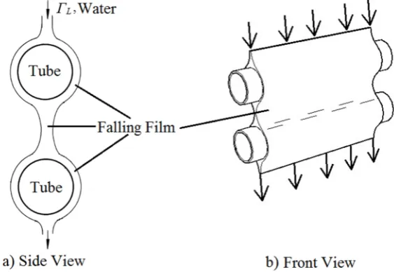
[image:33.595.180.462.532.726.2]When a liquid is flowing over horizontal tube, it was uniformly distributed around tube periphery and fell off at the bottom. This flow has been influenced by gravitational force and often referred to as falling liquid film (Robert, 1999). As the flow reached at the bottom of tube, it drips and fall freely between intertube spacing and impinges directly onto the surface of below tubes. The flow formed a thin layer on tube surface and it is also known as a liquid film. The properties of this flow is usually dominated by viscous, gravity and surface tension effects (Habert et al., 2009).
6 2.1.1 Falling Film Evaporator
7
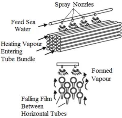
8 The evaporation of falling liquid film on horizontal tubes have been employed in a wide variety of commercial applications. In recent years, there are many improvement efforts have been done primarily for applications of desalination and refrigeration technology. However, in applications of air conditioning and refrigeration, the principle of falling film is not widely employed due to difficulties in liquid distribution and tube alignment. This affected the uniformity of flow and generate more dryout spaces especially inside deep bundles (Ribatski & Jacobi, 2005). The increasing use of horizontal falling film evaporation to remove undesired minerals from saline water has brought an impact to the conventional heat exchangers such as the coil and flooded evaporation. The flooded evaporation systems have received less attention and being replaced gradually in recent years. In configuration of horizontal tubes as shown in Figure 2.3, the sprayed liquid is to be evaporated on outside tube bundle. The heating fluid flows inside the tube. The liquid outside the tube forms a thin film flowing around the tube. When it reaches the bottom of tube, it drips off onto the tube below. One particular advantage of horizontal falling film evaporation compared to vertical unit is reduction of liquid distribution problems onto the tube surface. During a steady-state operation in vertical unit, the same amount of liquid is fed and distributed uniformly around the periphery of each tube. However, the even liquid distribution onto the horizontal tube surface is done by adjusting sprays nozzles or perforated plates on the top of tube bundle. Another advantages of horizontal falling film evaporation including high heat transfer rates at low liquid flow rates, small temperature differences and pressure drop over the tubes is negligible (Kakac & Whalley, 1991). In addition, this unit can be operated with even lower pressure drops compared to the vertical design. In the case of vertical unit, the tubes must be oriented precisely in vertical way and any adjustment required a greater tolerance of deviation compare with horizontal falling film evaporator.
9 evaporation have been extensively utilized in MED system and the performance improvement efforts are still ongoing over time.
Figure 2.3: Configuration of horizontal falling film evaporator (Ettouney & Wilf, 2009)
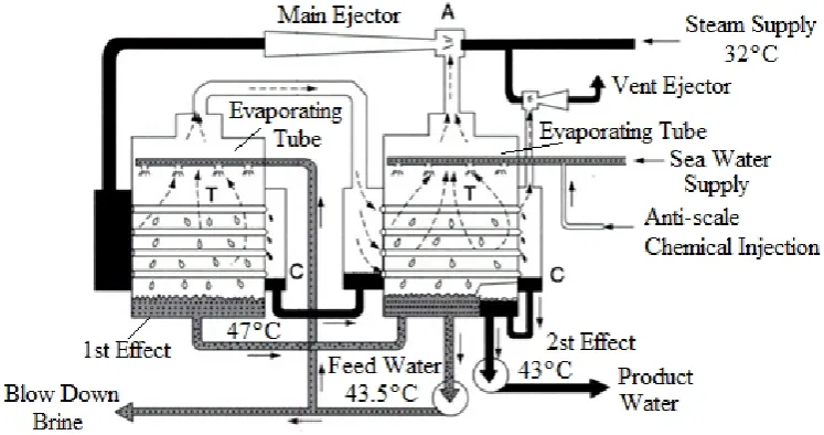
10 driven by a small quantity of high pressure steam and deliver a hotter compressed mixture of stream and vapour to the tubes of the first effect. On the shell side of each effect, the seawater supply is sprayed onto the outside of the evaporator tubes. Part of rejected brine from seawater in the last effect is reused as feed to the first effect. The product of fresh water is collected in the last effect (E. Delyannis & Belessiotis, 2006).
Figure 2.4: Schematic diagram of MED-TVC with 2 effects (Delyannis & Belessiotis, 2006)
The working principle of MVC unit is quite similar to TVC unit unless the compressor is used to reheat the vapour to higher temperatures as shown in Figure 2.5. The MVC system contains five major elements, which include mechanical vapour compressor, evaporation, preheaters for the intake seawater, brine and product pumps, and venting system. The system of MVC unit is driven by electric power and it does not require any external heating source. The low operation temperature of 60ºC in MVC unit allows for reduced scaling and heat losses as well as minimize requirement of thermal insulation (El-Dessouky & Ettouney, 2002). The maximum boiling temperature of brine is 70ºC (Ettouney & Wilf, 2009).
11
Figure 2.5: Schematic diagram of MED-MVC with simplified design (El-Dessouky & Ettouney, 2002)
Figure 2.6: Schematic diagram of MED-MVC with two effects (Sidem & Entropie, 2009)
[image:39.595.138.500.355.617.2]12 charge. With this advantage, falling film evaporation was economical used for high costs of HFCs and HCFCs refrigerant in refrigeration industry and also increased safety in the case of toxic ammonia. Falling film evaporation are expected to provide a high ratio of refrigeration capacity to refrigerant charge.
Figure 2.7: Ammonia-water chiller for air conditioning and refrigeration system (Jabardo & Gonzalez, 1992)
2.2 Characteristics of Falling Liquids Film on Horizontal Tube
13 and pressures to ensure the accuracy of data with acceptable ranges. The studies involving falling liquid film on horizontal tube requires several standardization for some important parameters. It is essential to understand and develop standards measurement in order to enable comparability between two or more configurations of falling liquid film. The use of software in analysis has increased rapidly over the past few decades. The growth leads to a better development performances and high demands in research. The Computational Fluid Dynamics (CFD) has brought a great understanding in development of thermal fluids analysis. The CFD softwares are capabled to cover all characteristics of falling liquid film, physical modeling of heat transfer, turbulence model flow, and reactions for industrial applications ranging from bubble columns to oil platforms, from blood flow to semiconductor manufacturing, from clean room design to wastewater treatment plants and from air flow over an aircraft wing to combustion in a furnace. The complex analysis is no longer impossible with assistance of this software. This section describes all related parameters of falling liquid film.
2.2.1 Spray Density, ΓL of Falling Film on Horizontal Tube
14
Figure 2.8: ΓLremains constant regardless of tube length
With developments of falling liquid film technologies, various designs have been constructed to meet the suitability of any operating conditions and sizes. Furthermore, the increasing number of studies in recent years have involved with different tubes length between one another. The common unit of flow rates kg/s were also changed corresponding to length of each tube. The diversity of these values need to be standardized to allow comparisons between different systems. The best way to implement this standards is by adopting a new unit called kg/sm instead of kg/s in common analysis of liquids flow. In order to prove that unit of kg/sm remains constant regardless of tube length, all derivations are explained in the following page. By definition, the flow rates per unit length of tube or known as spray density,
ΓL, is defined as:
l t m
ΓL (2.1)
l m
ΓL (2.2)
wherem is mass of water, m is water mass flow rate, t is time and is tube length. Based on Figure 2.7, l2 is longer than l1 (l2>l1) with magnification factor
α.αindicates length ratio between l1and l2 . The variables are related by
l α
l2 1 (2.3)
l l α
1 2
15 The relation between flow rates of m2 and m1 are also governed by thisα:
m α
m2 1 (2.5)
m m α 1 2 (2.6) Thus, m m l l α 1 2 1 2 (2.7) Hence, l m l m Γ 2 2 1 1
L (2.8)
[image:43.595.152.486.521.669.2]In other words, Γ L remains constant regardless of tube length as shown in Equation (2.8). This unit facilitates any comparison between two different systems of falling liquid film. This unit is typically used to classify 3 different types of flow patterns as will be mentioned in section 2.2.8. The Equation (2.8) can be clearly understood by considering two cases of falling film as illustrated in Figure 2.9. The length of tube in case 2 is three times longer than case 1. The pitch tube, S for both cases were fixed at 0.04 m. The mass flow rates per unit length of tube ΓL for both cases were compared as shown in the following calculation.
Figure 2.9: Two different length of tube
16
3 1 3
α (2.9)
The mass flow rates m2 for case 2 is determined using Equation (2.5) as
follows:
m 3
m2 1 (2.10)
s / kg 1 3
m2 (2.11)
s / kg 3
m2 (2.12)
Hence, the unit of kg/sm for both cases are : Case 1:
kg/sm 1 1 1
ΓL (2.13)
Case 2:
kg/sm 1 3 3
ΓL (2.14)
In conclusion, Γ L remained at the same values even though each tube was different in length.
2.2.2 Working Fluids of Horizontal Falling Film
17 fluid at low temperatures. Ribatski & Jacobi (2005) showed that various types of working fluid were used in their experiment and the most preferable one is water. Water was the main option as a working fluid in many previous analysis. It was a key of choice for many researchers due to its form of liquid at room temperature under atmospheric pressures. It is also readily available at a low cost and easily handled. As specialized studies required the use of a real fluids such as a refrigerant of ammonia, R-11, R-13 and R-134a, water is no longer suitable to be used in analysis. The results of these studies were closed the real process of horizontal falling film evaporation. Based on results provided by Houet al.(2012) in Figure 2.10, the film thickness,δ between seawater and pure water are almost the same.
Figure 2.10: Variation of film thickness between seawater and pure water (Houet al., 2012)
2.2.3 Dimensions and Material Used in Horizontal Falling Film
18 used by most of researchers. The limits range of their selections were typically in between 19.05 mm up to a bigger size of 132 mm. The most preferable among researchers were 25.4 mm.According to Hisham (2009), the thicknessof falling film evaporation tubes used ranged between 0.01 to 0.05 m and their corresponding length is between 5 to 8m. The tube are normally made of stainless steel (304 or 316) with highly polished surface to conform the hygienic standard (George, 2002).
2.2.4 Water Boiling Point During MEHT Operation
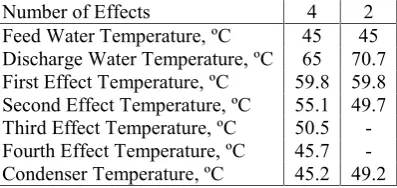
[image:46.595.222.421.616.710.2]The normal range of water boiling point operates in falling film evaporation varies as low as 8 kPa to as high as 31 kPa of absolute pressures. In these operating conditions, a varying reduced pressure is to reduce the boiling point of working liquids and to allow a low temperature operation. The type and number of MEHT’s effects are factors affecting the temperature conditions of each unit. Each effect is slightly different compare to unit located next to it. The first and warmest effect is typically operated at a temperature below 70°C to avoid scale formation. In normal operating conditions of MED, the working temperatures and pressures ranges between 40°Cto 70°C corresponding to 7.3 kPa and 32 kPa respectively(Bighamet al., 2015). Table 2.1 shows several operating parameters for two MEHT with different number of effects.
Table 2.1: Operational data of two MEDwith different number of effects(Bighamet al., 2015)
Number of Effects 4 2
Feed Water Temperature, ºC 45 45 Discharge Water Temperature, ºC 65 70.7 First Effect Temperature, ºC 59.8 59.8 Second Effect Temperature, ºC 55.1 49.7 Third Effect Temperature, ºC 50.5 -Fourth Effect Temperature, ºC 45.7 -Condenser Temperature, ºC 45.2 49.2
19
(2007) was maintained at the evaporation temperature and pressure in the range of 40°C/0.074 bar to 90°C/0.7 bar. Ribatski & Jacobi, 2005 reviewed various temperature and pressure used in previous studies. These differences depended on objectives of each study. Most of their working temperatures ranges between 40°C to a maximum of 70°C.
2.2.5 Ideal Gas Equation for Environmental Air
The ideal gas equation of state relates several properties including pressure, temperature and specific volume by three equations (Cengel & Boles, 2006). These equations are shown as follows:
RT ν
Pa a a (2.15)
where Pa is absolute pressure of air, νa is specific volume of air, R is gas constant, Ta is absolute temperatures of air and ρa is mass density of air. The gas
constant R is fixed at 0.287 kJ/kg K. All real gases approach ideal-gas behavior at low pressures, and therefore the use of ideal gas equation in this condition is resulted with no deviation of errors. However, the properties of gases significantly deviated from ideal-gas behavior at states near the saturation region and the critical point. The deviation from ideal-gas behavior is corrected by introduction of correction factors called compressibility factorZand defined as follows:
RT ν P Z
a a a
(2.16)
P P P
cr a
R (2.17)
T T T
cr a
20 The terms PR, Pcr, TR and Tcrare reduced pressure, critical pressure, reduced temperature and critical temperature respectively. The values of PR , T R andZare found in Nelson – Obert generalized compressibility chart provided by Cengel & Boles (2006).
2.2.6 Archimedes Number for Falling Film Thickness
The Archimedes number, Ar is used in determining falling film thickness. By definition, the equation is defined as follows:
rces Viscous Fo
rces Gravity Fo
Ar (2.19)
μ d ρ g Ar
L L
2 3
(2.20)
where g is gravitational acceleration, ρLis mass density of liquid, d is
diameter of tube, and
μ
L is dynamic viscosity of liquid.2.2.7 Humidity of Environmental Air
21 2.2.8 Reynolds Number of Falling Liquid Film
The most used formula of Reynolds number, Re no., for falling film on horizontal tubes was referred to several previous studies and it was defined as Equation (2.21) (Adib, Heyd, & Vasseur, 2009; Çengel & Cimbala, 2006; Jafar et al., 2007; Li, Wu, & Luo, 2010; Liu & Yi, 2002). The derivation of this formula maybe found in works of Ahmed (2014).
μΓ Re
L L
L 4 (2.21)
[image:49.595.144.498.586.711.2]where ΓL is mass flow rate of liquid film per unit length of tube and
μ
Lis dynamic viscosity of liquid. On the other hand, the flow modes are basically classified into three different patterns when falling liquid films is flowing over horizontal cylinders. Each of these flow patterns is known as droplet mode, the jet or column mode and the continuous liquid sheet mode as shown in Figure 2.11. The flow patterns of falling film on horizontal tube plays important role in heat and mass transfer of falling liquids film. The complex nature of these process have received wide attention from many researchers. Many theoretical and experimental studies have provided valuable contributions and generally, they observed by means of control over the mass flow rate and other physical parameters including pitch length, shape of tube surface, and types of fluids used as reported by Mohamed (2007).22 Apart from that, two patterns of transition regions between these three flow modes were also described as droplet-columnar and columnar-sheet. In analysis of horizontal falling film, the flow patterns was closely related to Reynolds number,Re no.. It was used as key parameter to determine specific type of flow patterns on horizontal falling film. Many previous researchers tried to define these flow patterns in details to get a more accurate range ofRe no.In addition, the experimental results of several previous literatures showed a certain ranges of Re no. as shown in the following Table 2.2.
Table 2.2: Range ofRe no.corresponding to flow patterns
Scenarios of Water Flow Pattern
Reynolds Number,Re no.
Previous Literatures With Zero Velocity of Air Flow
(Armbruster & Mitrovic, 1998) (Mohamed, 2007) (Schausber geret al.,
2009) (F. A. Jafar, Thorpe, & Turan, 2009) (J. Chen, Zhang, & Niu, 2015)
a. Droplet 0-84.5 0-210 150-200 0-200
-b. Droplet - Droplet
/ column - - - - 450
c. Droplet - column 84.5-110 210-290 - -
-d. Droplet / column
- Column - - - - 567
e. Column 110-301 290-620 315-600 200-800
f. Column - Column
/ sheet - - - - 1174
g. Column - sheet 301-389 620-780 - -
h. Column / sheet
-Sheet - - - - 1311
i. Sheet Re no.≥ 389 780-1000 Re no.600 ≥ 800-2000
-Temperature, ºC 50 25 50 20 10
24 2.2.9 Environmental Heat Transfer on Horizontal Falling Film
[image:52.595.258.381.357.548.2]Several investigations of heat transfer process have examined significant effect of environment and intertube spacing on falling film. All experiments have been conducted with purpose to enhance heat transfer process on horizontal falling film. This effect is more pronounced under influence of air flow. According to Armbruster & Mitrovic (1998), there were two different locations on falling film system where heat transfer process took place in two different ways. The first process was convection between intertube spacing while the other was conduction on tube surface. Both processes were varied independently from one another. The processes of heat transfer on the tube surface took place as the water at temperature different than that of the surface.
Figure 2.12: Heat and mass transfer processes associated with horizontal falling film (Armbruster & Mitrovic, 1998)
REFERENCES
Abed, A. M., Alghoul, M. A., Yazdi, M. H., Al-Shamani, A. N., & Sopian, K. (2015). The role of enhancement techniques on heat and mass transfer characteristics of shell and tube spray evaporator: a detailed review. Applied Thermal Engineering,75, 923–940.
Abraham, R., & Mani. (2015). Heat transfer characteristics in horizontal tube bundles for falling film evaporation in multi-effect desalination system. Desalination,375, 129–137.
Adib, T. A., Heyd, B., & Vasseur, J. (2009). Experimental results and modeling of boiling heat transfer coefficients in falling film evaporator usable for evaporator design. Chemical Engineering and Processing: Process Intensification, 48(4), 961–968.
Ansys Fluent Notes v6.3. (2006). Solver Settings. Pennsylvania, USA: Notes.
Armbruster, R., & Mitrovic, J. (1998). Evaporative cooling of a falling water Film on horizontal tubes.Experimental Thermal and Fluid Science,18(1998), 183–194. Bigham, S., KouhiKamali, R., & P. Zadeh, M. (2015). A general guide to design of
falling film evaporators utilized in multi effect desalination units operating at high vapor qualities under a sub-atmospheric condition.Energy,84, 279–288. Bourouni, K., Martin, R., Tadrist, L., & Tadrist, H. (1998). Modelling of heat and
mass transfer in a h0rizontal-tube falling-film evaporator for water desalination. Desalination,116(11).
Cengel, Y. A., & Boles, M. (2006). Property of Pure Substances. Thermodyamics: An Engineering Approach. 5th Edition. New York, Unite States of America: McGraw-Hill.
187 Chen, J., Zhang, R., & Niu, R. (2015). Numerical simulation of horizontal tube
bundle falling film flow pattern transformation.Renewable Energy,73, 62–68. Chen, X., Shen, S., Wang, Y., Chen, J., & Zhang, J. (2015). Measurement on falling
film thickness distribution around horizontal tube with laser-induced fluorescence technology.International Journal of Heat and Mass Transfer,89, 707–713.
E. Delyannis, & Belessiotis, B. (2006). Desalination.Encyclopedia of Environmental Science and Engineering,Volumes 1 & 2.5th Edition. Boca Raton: CRC Press. El-Dessouky, H. T., & Ettouney, H. M. (2002). Fundamentals of Salt Water
Desalination.5th Edition. Netherlands. Elsevier.
Cipollina, G. Micale, & L. Rizzuti (Eds.) (2009). Seawater Desalination: Conventional and Renewable Energy Processes. Heidelberg Berlin: Springer Science & Business Media.
Fernández-Seara, J., & Pardiñas, Á. Á. (2014). Refrigerant falling film evaporation review: Description, fluid dynamics and heat transfer. Applied Thermal Engineering,64(1–2), 155–171.
Fridhi Hadia, Kaiss Ahmed, Soua Wadhah, T. L. (2014). Flow Patterns And Wavelength Measurement For Liquid Film Falling. 2014 International Conference on Composite Materials & Renewable Energy Applications (ICCMREA), 1–6.
Gong, L., Shen, S., Liu, H., Mu, X., & Chen, X. (2014). Three-dimensional heat transfer coefficient distributions in a large horizontal-tube falling film evaporator.Desalination,357, 104–116.
Gstoehl, D., Roques, J. F., Crisinel, P., & Thome, J. R. (2004). Measurement of Falling Film Thickness Around a Horizontal Tube Using a Laser Measurement Technique.Heat Transfer Engineering,25(8), 28–34.
Habert, Mathieu, Thome, & Richard, J. (2009). Falling film evaporation on a tube bundle with plain and enhanced tubes. École Polytechnique Fédérale De Lausanne: Ph.D. Thesis.
188 Hou, H., Bi, Q., Ma, H., & Wu, G. (2012). Distribution characteristics of falling film
thickness around a horizontal tube.Desalination,285, 393–398.
Hou, H., Bi, Q., & Zhang, X. (2012). Numerical simulation and performance analysis of horizontal-tube falling-film evaporators in seawater desalination. International Communications in Heat and Mass Transfer,39(1), 46–51.
Hu, & Jacobi. (1998). Departure-site spacing for liquid columns falling between horizontal circular tubes. Experimental Thermal and Fluid Science, 16, 322– 331.
Incropera, F. P., DeWitt, D. P., Bergman, T. L., & Lavine, A. S. (2007). Fundamentals of Heat and Mass Transfer. 6th Edition. United States: John Wiley & Sons, Inc.
Jabardo, & Gonzalez. (1992).Falling Film Ammonia Evaporators. University of Illinois: Ph.D. Thesis.
Jafar, F. A., Thorpe, G. R., & Turan, Ö. F. (2009). Flow Mode Characterisation of Liquid Films Falling on Horizontal Plain Cylinders. Seventh International Conference on CFD in the Minerals and Process Industries, (December), 1–6. Jafar, F., Thorpe, G., & Turan, O. F. (2007). Liquid Film Falling on Horizontal
Circular Cylinders, (December), 1193–1200.
Jafar, Thorpe, & Turan. (2007). Liquid Film Falling on Horizontal Circular Cylinders. 16th Australasian Fluid Mechanics Conference, (December), 1193– 1200.
Kakac, S., & Whalley. (1991). Boilers, evaporators, and condensers. 1st Edition. Kanada: John Wiley & Son, Inc.
Keyence. (2011). Ultra High-accuracy Reliable Measurement. Elmwood Park, New Jersey: Marketing Brochure.
Kocamustafaogullari, G., & Chen, I. Y. (1988). Falling film heat transfer analysis on a bank of horizontal tube evaporator.AIChE Journal,34(9), 1539–1549.
Lee, S., Köroğlu, B., & Park, C. (2012). Experimental investigation of capillary-assisted solution wetting and heat transfer using a micro-scale, porous-layer coating on horizontal-tube, falling-film heat exchanger.International Journal of Refrigeration,35(4), 1176–1187.
189 Li, W., Wu, X.-Y., Luo, Z., & Webb, R. L. (2011). Falling water film evaporation on newly-designed enhanced tube bundles.International Journal of Heat and Mass Transfer,54(13–14), 2990–2997.
Li, W., Wu, X., & Luo, Z. (2010). Falling Film Evaporation of Water on Horizontal Configured Tube Bundles.Proceedings of the 14th International Heat Transfer Conference,4, 495–502.
Liu, H., Shen, S. Q., Gong, L. Y., & Chen, S. (2013). Shell-side two-phase pressure drop and evaporation temperature drop on falling film evaporation in a rotated square bundle.Applied Thermal Engineering, 1–7.
Liu, Z., & Yi, J. (2002). Falling Film evaporation heat transfer of water / salt mixtures from roll-worked enhanced tubes and tube bundle, Applied Thermal Engineering, 22, 83–95.
Liu, Shen, Gong, & Chen. (2014). Shell-side two-phase pressure drop and evaporation temperature drop on falling film evaporation in a rotated square bundle.Applied Thermal Engineering, 69(1–2), 214–220.
Luo, L., Zhang, G., Pan, J., & Tian, M. (2013). Flow and heat transfer characteristics of falling water film on horizontal circular and non-circular cylinders. Journal of Hydrodynamics, Ser. B,25(3), 404–414.
Maroulis, Z. B., & Saravacos, G. D. (2003).Food Process Design. 1st Edition. New York, United States: CRC Press.
Meijun, Lu, Y., Zhang, S., & Xiao, Y. (2016). A numerical study of effects of counter-current gas flow rate on local hydrodynamic characteristics of falling films over horizontal tubes.Desalination,383, 68–80.
Merrell, & Floyd. (1998).Simplicity and Complexity: Pondering Literature, Science, and Painting. 4rd Edition. Michigan: University of Michigan Press.
Mohamed, A. M. I. (2007). Flow behavior of liquid falling film on a horizontal rotating tube.Experimental Thermal and Fluid Science,31(4), 325–332.
Ouldhadda, D., Idrissi, A. Il, & Asbik, M. (2002). Heat transfer in non-Newtonian falling liquid film on a horizontal circular cylinder. Heat and Mass Transfer/Waerme- Und Stoffuebertragung,38(7–8), 713–721.
190 Piotr Cyklis, P. M. (2016). The Influence of The Spatial Discretization Methods on The Nozzle Impulse Flow Simulation Results. IX International Conference on Computational Heat and Mass Transfer ICCHMT 2016, (May).
Qiu, Q., Zhu, X., Mu, L., & Shen, S. (2015). Numerical study of falling film thickness over fully wetted horizontal round tube.International Journal of Heat and Mass Transfer,84, 893–897.
Ribatski, G., & Jacobi, A. M. (2005). Falling-film evaporation on horizontal tubes— a critical review.International Journal of Refrigeration,28(5), 635–653.
Ribatski, G., & Thome, J. R. (2007). Experimental study on the onset of local dryout in an evaporating falling film on horizontal plain tubes. Experimental Thermal and Fluid Science,31(6), 483–493.
Rogers. (1981). Laminar Falling Film Flow and Heat Iransfer Characteristics on Horizontal Tubes, Department of Mechanical and Aeronautical Engineering, 59.
Rogers, J. T., & Goindip, S. S. (1989). Experimental Laminar Falling Film Heat Transfer Coefficients on a Large Diameter Horizontal Tube. The Canadian Journal of Chemical Engineering,67, 560–568.
Ruan, B., Jacobi, A. M., & Li, L. (2009). Effects of a countercurrent gas flow on falling-film mode transitions between horizontal tubes. Experimental Thermal and Fluid Science,33(8), 1216–1225.
Sait, H. H. (2013). Heat transfer analysis and effects of feeding tubes arrangement, falling film behavior and backsplash on ice formation around horizontal tubes bundles.Energy Conversion and Management,73, 317–328.
Sait, & Hani. (2012). Heat Transfer Characteristics and Temperature Distribution of Falling Film over Horizontal Hot Tube Arrays. Asian Transactions on Engineering,2(3), 24–34.
Saravacos, G., & Athanasios. (2002). Handbook of Food Processing Equipment. New York: Kluwer Academic/Plenum Publishers.
Schausberger, Paul, Nowak, Johannes, Medek, Otto and Paul. (2009). Heat Transfer in Horizontal Falling Film Evaporators. IDA World Congress on Desalination and Water Reuse(Vol. 327, pp. 1–10).
191 Shen, S., Gong, L., Liu, H., Mu, X., & Liu, R. (2014). Characteristic study of steam maldistribution in horizontal-tube falling film evaporators. Applied Thermal Engineering, 1–13.
Subramaniam, V., & Garimella, S. (2014). Numerical study of heat and mass transfer in lithium bromide-water falling films and droplets. International Journal of Refrigeration,40, 211–226.
Thome, J. R. (2004).Engineering Data Book III. Lausanne Switzerland: Wolverine Tube, Inc.
Thulukkanam, & Kuppan. (2000). Heat Exchanger Design Handbook. New york: CRC Press.
Wang, X., He, M., Fan, H., & Zhang, Y. (2009). Measurement of falling film thickness around a horizontal tube using laser-induced fluorescence technique. Journal of Physics: Conference Series,147, 12039.
Wang, X., Hrnjak, Elbel, Jacobi, & Maogang. (2012). Flow Modes and Mode Transitions for Falling Films on Flat Tubes. Journal of Heat Transfer, 134(2), 21801.
Wildebrand, C., Glade, H., Will, S., Essig, M., Rieger, J., Büchner, K.-H., & Brodt, G. (2007). Effects of process parameters and anti-scalants on scale formation in horizontal tube falling film evaporators.Desalination,204(1–3), 448–463. Xu, L., Ge, M., Wang, S., & Wang, Y. (2004). Heat-transfer film coefficients of
falling film horizontal tube evaporators.Desalination,166, 223–230.
Yang, L., Liu, Y., Yang, Y., & Shen, S. (2016). Microscopic mechanisms of heat transfer in horizontal-tube falling film evaporation.Desalination,394, 64–71. Yang, L., & Shen, S. (2008). Experimental study of falling film evaporation heat
transfer outside horizontal tubes.Desalination,220(1–3), 654–660.
Yang, L., Shen, S., Xingsen, Shengqiang, Yang, Y., & Liu, X. (2012). Experimental study of falling film evaporation heat transfer outside horizontal tubes. Desalination,220(1–3), 654–660.