COMPARISON OF DATA HIDING USING LSB AND DCT FOR IMAGE.
ZAMZAM HOHAMED AHMED
A project report submitted in partial
fulfillment of the requirement for the award of the Degree of Master of Computer Science (Information Security)
Faculty of Computer Science and Information Technology Universiti Tun Hussein Onn Malaysia
ABSTRACT
ABSTRAK
TABLE OF CONTENTS
TITLE i
DECLARATION ii
DEDICATION iv
ACKNOWLEDGEMENT v
ABSTRACT vi
ABSTRAK vii
TABLE OF CONTENTS viii
LIST OF TABLES xi
LIST OF FIGURES xii
ABBREVIATIONS xiii
CHAPTER 1 INTRODUCTION 1
1.1 Background 1
1.1 History of steganography 2
1.2 Problem statement 2
1.3 Objectives 3
1.4 Scope 3
1.5 Dissertation outline 4
CHAPTER 2 LITERATURE REVIEW 5
2.1 The basic framework of steganography 5
2.2 The purpose of steganography 7
2.3 Types of steganography 7
2.3.1 Text steganography 8
2.3.3 Image steganography 9
2.4 Image format 9
2.4.1 Tiff file 10
2.4.2 Gif file 10
2.4.3 Bmf file 10
2.4.4 Jpeg file 11
2.5 Image compression 11
2.5.1 Jpeg compression 12
2.6 Steganography domain and technique 12
2.6.1 Spacial domain 13
2.6.1.1 Least significant bit Technique 13 2.6.1.1.1 Lsb algorithm 15
2.6.2 Frequency domain 16
2.6.2.1 Discrete cosine transform technique 16 2.6.2.2 Discrete wavelet transform 18 2.7 Peak signal to noise ratio (PSNR) 18
2.8 Summary 19
CHAPTER 3 METHODOLOGY 20
3.1 The proposed method 20
3.1.1 Proposed framework 21
3.2 Least significant bit technique 22 3.3 Discrete cosine transform technique 24
3.4 Comparison and measurement 25
2.5 Summary 26
CHAPTER 4 IMPLEMENTATION 27
4.1 Introduction 27
4.3.2 Dct extracting algorithm in matlab 33 4.4 The peak signal to noise ratio for Dct and lsb 35
4.5 Summary 36
CHAPTER 5 RESULT AND DISCUSSION 37
5.1 Introduction 37
5.2 Least significant bit (LSB) technique 37 5.2.1 Lsb embedding algorithm result 38 5.2.2 Lsb extracting algorithm result 39 5.3 Discrete cosine transform (DCT) technique 40 5.3.1 Dct embedding algorithm result 40 5.3.2 Dct Extracting algorithm result 41
5.4 Comparison and measurement 42
5.4.1 Analysis of test result for lsb 47 5.4.2 Analysis of test result for dct 48 5.4.3 Analysis of test result for lsb and dct 49
5.5 Summary 51
CHAPTER 6 CONCLUSION 52
6.1 Conclusion 52
6.2 Future work 53
REFERENCES 54
LIST OF TABLES
5.1 BMP images using LSB 43
5.2 BMPimages using DCT 44
5.3 LSB stego images 256x256 45
5.4 LSB stego images 512x512 45
5.5 DCT stego images 256x256 46
5.6 DCT stego images 512x512 46
LIST OF FIGURES
2.1 The different embodiment disciplines of information hiding 6
2.2 General model of Steganography 8
2.3 Algorithm of Least Significant Bit 15
2.4 Block diagram of JPEG encoder and decoder 17
2.5 One Dimensional DCT 17
2.6 Two Dimensional DCT 18
3.1 Proposed Framework 21
3.2 LSB embedding algorithm 23
3.3 LSB extraction algorithm 23
3.4 DCT based embedding algorithm 24
3.5 DCT based extraction algorithm 25
4.1 LSB based embedding implementation code in Matlab 28
4.2 LSB based extracting implementation code in Matlab 29
4.3 DCT based embedding implementation code in Matlab 31
4.4 DCT based extracting implementation code in Matlab 34
4.5 Matlab code for PSNR of the LSB stego image 35
4.6 Matlab code for PSNR of the DCT stego image 36
5.1 The result obtained by running LSB embedding algorithm 38
5.2 The result obtained by running LSB extraction algorithm 39
5.3 The result obtained by running DCT embedding algorithm 40
5.4 The result obtained by running DCT extracting algorithm 41
5.5 LSB stego images 512x512 and 256x256 47
5.6 DCT stego images 512x512 and 256x256 48
5.7 Stego images 512x512 resolutions for LSB and DCT 49
LIST OF ABBREVIATIONS
LSB Least Significant Bit MSB Most Significant Bit DCT Discrete Cosine Transform DWT Discrete Wavelet Transform DFT Discrete Fourier Transform PSNR Peak Signal-to-Noise Ratio
MSE Mean Squared Error
HVS Human Visibility System TIFF Tagged Image Format File GIF Graphic Interchange Format
BMP Bitmap
JPEG Joint Photographic Experts Group
ASCII American Standard Code for Information Interchange
CHAPTER 1
INTRODUCTION
1.1 Background
1.1.1 History of Steganography
Steganography goes back to ancient times and used by different cultures such as: Greeks, Chinese, and medieval Europe. A famous which case dates back to 1586, when Mary Queen of Scots was conspiring to have Queen Elizabeth of England assassinated, with a view to taking over the English throne [1]. Also during the 1980’s, Margaret Thatcher became so irritated at press leaks of cabinet documents that she had the word processors programmed to encode their identity in the word spacing, so that disloyal ministers could be traced [2]. Similar techniques are now undergoing trials in an electronic publishing project, with a view to hiding copyright messages and serial numbers in documents. In some applications, it is enough to hide the identity of either the sender or the recipient of the message, rather than its very existence [3]. Modern steganography entered the world in 1985 with the advent of the personal computer being applied to classical steganography problems. Also in modern Steganography practice the larger the cover message is relative to the hidden message, the easier it is to hide the latter [4].
1.2 Problem Statement
differently in digital image, audio and video file, it’s difficult to detect, only receiver can detect it and it can be done faster with the large number of softwares.
1.3 Objectives
The Objectives of this project is to:
1. To implement steganography images based on Least Significant Bit (LSB) and Discrete Cosine Transform (DCT) techniques in Matlab
2. To test these techniques using cover images with 256x256 and 512x512 resolutions 3. To compare and analyze using Peak Signal to Noise Ratio (PSNR)
1.4 Scope
The scope of this research is:
1. Hiding data in image steganography
2. Using Least Significant Bit (LSB) and Discrete Cosine Transform (DCT) 3. Do testing on cover images with 256x256 and 512x512 resolutions only
4. BMP file format is chosen to be used in this dissertation due to their higher resolution compared to other images. The BMP files are uncompressed, hence they are large. The advantage of using BMP files is simplicity and wide acceptance of BMP files in windows programs
1.5 Dissertation Outline
CHAPTER 2
LITERATURE REVIEW
2.1 The Basic Framework of Steganography
An Example of steganography can be given in terms of communication between two people, Alice and Bob,where Alice and Bob are two inmates who wish to communicate in order to exchange some secret information. However, all communication between them is examined by the eavesdropper, Wendy, the third party who will try hardly to disclose, alter and/or destruct their secret message.
Specifically, in the general model for steganography, illustrated in Figure 2.1, Alice wishes to send a secret message m to Bob. In order to do so, she "embeds" m into a cover-object c, and obtains a stego-object s. The stego-object s is then sent through the public channel. Thus we have the following definitions:
iii. Stego-object: is the combination of the cover object, the stego-key and the secret message.
[image:15.612.116.533.360.623.2]In a pure steganography framework, the technique for embedding the message is unknown to Wendy and shared as a secret between Alice and Bob. However, it is generally considered that the algorithm in use is not secret but only the key used by the algorithm is kept as a secret between the two parties, this assumption is also known as Kerchoff's principle in the field of cryptography. The secret key, for example, can be a password used to seed a pseudo-random number generator to select pixel locations in an image cover-object for embedding the secret message (possibly encrypted). Hence, there is a need for a cover media, stego function, stego- key and the secret message to be hidden. The cover media can be a plaintext, still image, video and audio. Performing data hiding in Image was studied in a wide variety of literatures.
2.2 The Purpose of Steganography
According to the major objective of steganography is to prevent some unintended observer from stealing or destroying the confidential information. There are some factors to be considered when designing a steganography system: [7]
i. Invisibility: Invisibility is the ability to be unnoticed by the human.
ii. Security: Even if an attacker realizes the existence of the information in the stego object it should be impossible for the attacker to detect the information. The closer the stego image to the cover image, the higher the security. It is measured in terms of Peak Signal to Noise Ratio (PSNR).
2.3 Types of Steganography
A cover object is the object designated to carry the embedded bits or secret information. The cover objects can be a text file, image file, audio file or video file. These different type of steganography with various cover objects are discussed further in the following sections.
2.3.1 Text Steganography
[image:17.612.117.539.100.281.2]Historically hiding information in the text was a simple and the most important method of steganography but Due to the beginning of the Internet and due to the different type of digital file formats it has decreased in importance. Text steganography using digital files is not used very often because the text files have a very small amount of redundant data [8].
2.3.2 Audio Steganography
Audio steganography is masking, which exploits the properties of the human ear to hide information unnoticeably. An audible, sound becomes inaudible in the presence of another louder audible sound. This property allows the selection of the channel in which the information will be hidden. Although it is similar to images in steganographic potential, the larger size of meaningful audio files makes them less likely to use than images [8].
2.3.3 Image Steganography
Image Steganography will be used as cover object or host image for this project because Images are considered as the most popular file formats used in steganography. They are known for constituting a non-causal medium, due to the possibility to access any pixel of the image at random. In addition, the hidden information could remain invisible to the eye. However, the image steganography techniques will exploit "holes" in the Human Visual System (HVS) [8] [9].
2.4 Image Format
2.4.1 TIFF File
Tagged Image Format File (TIFF) is an image format file for high quality graphics. TIFF files were created in the 1986 as a file format for scanned imaged in an attempt to get all companies to use one standard file format instead of multiple. Though TIF files originally only supported black and white, the update in 1988 added a color palette [10].
2.4.2 GIF File
Graphics Interchange Format is used for the purpose of storing multiple bitmap images in a single file for exchange between platforms and images. It is often used for storing multibit graphics and image data. GIF is not associated with a particular software application but was designed “to allow the easy interchange and viewing of image data stored on local or remote computer systems” [10] [11].
2.4.3 BMP File
Information. Images which are less than 16 bit have an additional sub-block within the header labeled the Color Palette [12] [13].
2.4.4 JPEG File
Joint Photographic Experts Group (JPEG) format is one of the Transform Domain Techniques which has an advantage over LSB techniques because they hide information in areas of the image that are less exposed to compression, cropping, and image processing [9]. Also JPEG is most common image file format on the internet owing to the small size of resultant images obtained by using it, and it is efficient for appearing the stage image to something similar to the original image [14].
2.5 Image Compression
When working with larger images of greater bit depth, the images tend to become too large to be transmitted over a standard Internet connection. In order to display an image in a reasonable amount of time, techniques must be incorporated to reduce the image’s file size. These techniques make use of mathematical formulas to analyze and condense image data, resulting in smaller file sizes. This process is called compression. In images there are two types of compression: lossy and lossless [9].
i. Lossless compression is known for being preferable when the original data should stay in its entirety. In this manner, the original image information will never be removed, and this makes it possible the reconstruction of the original data from the compressed data. This is typical of images in GIF and BMP.
something similar to the original image, but not the same as the original. JPEG compression uses this technique.
2.5.1 JPEG Compression
The process of embedding information during JPEG compression results in a stego image with a high level of invisibility, since the embedding takes place in the transform domain. Originally it was thought that steganography would not be possible to use with JPEG images, since they use lossy compression which results in parts of the image data being altered. JPEG images are the products of digital cameras, scanners, and other photographic image capture devices. This is simply why concealing secret information in JPEG images might provide a better disguise [9] [15].
For JPEG, the Discrete Cosine Transform (DCT) is used. It is important to recognize that the JPEG compression algorithm is actually divided into lossy and lossless stages. The DCT and the quantization phase form part of the lossy stage, while the Huffman encoding used to further compress the data is lossless. Steganography can take place between these two stages. Using the same principles of LSB insertion the message can be embedded into the least significant bits of the coefficients before applying the Huffman encoding. By embedding the information at this stage, in the transform domain, it is extremely difficult to detect, since it is not in the visual domain [16].
2.6 Steganography Domains and Techniques
discussions. The so-called spatial-domain refers to the fact that the secret is mixed into the distributed pixels (regions) directly. While in the frequency-domain, it is necessary to transform the host-image first using a frequency-oriented mechanism, such as a discrete cosine transformation based (DCT-based), wavelet-based, etc., after which the secret is then combined with the relative coefficients in the frequency-form image. Let us take another look at the spatial-domain manner. Generally speaking, it is simpler to achieve the goal of information hiding in the course of secret embedding. The least significant bit (LSB for short) secret embedding or LSB-like embedding is the most commonly used method in the spatial-domain approach [17].
2.6.1 Spatial Domain
These techniques use the pixel gray levels and their color values directly for encoding the message bits. These techniques are some of the simplest schemes in terms of embedding and extraction complexity. The major drawback of these methods is amount of additive noise that creeps in the image which directly affects the Peak Signal to Noise Ratio and the statistical properties of the image. Moreover these embedding algorithms are applicable mainly to lossless image-compression schemes like TIFF images. For lossy compression schemes like JPEG, some of the message bits get lost during the compression step. The most common algorithm belonging to this class of techniques is the Least Significant Bit (LSB) replacement technique.
2.6.1.1 Least Significant Bit Technique
(LSB) Embedding is simple. It exploits the fact that the level of precision in many image formats is far greater than that perceivable by the standard of human vision. Therefore, an altered image with slight variations in its colors will be indistinguishable from the original by a human being, just by looking at it.
When using the least significant bit of the pixels' color data to store the hidden message, the image itself is seemed unaltered. Modulating the least significant bit does not result in human-perceptible difference because the amplitude of the change is small. To hide a secret message inside an image, a proper cover image is needed. It is necessary to use a lossless compression format, because this method uses bits of each pixel in the image, otherwise the hidden information will get lost in the transformations of a lossy compression algorithm. When using a 24-bit color image, a bit of each of the red, green and blue color components can be used, so a total of 3 bits can be stored in each pixel. For example, the following grid can be considered as 3 pixels of a 24-bit color image, using 9 bytes of memory:
(00100111 11101001 11001000) (00100111 11001000 11101001) (11001000 00100111 11101001)
When the character A, which binary value equals 10000001, is inserted, the following grid results:
(00100111 11101000 11001000) (00100110 11001000 11101000) (11001000 00100111 11101001)
In this case, only three bits are needed to be changed to insert the character successfully. On average, only half of the bits in an image will be needed to be insider modified to hide a secret message using the maximal cover size. The result changes that are made to the least significant bit are too small to be recognized by the human visual system (HVS), so the message is effectively hidden [18].
2.6.1.1.1 LSB Algorithm
i. Select a cover image of size M*N as an input.
ii. The message to be hidden is embedded in RGB component only of an image. iii. Use a pixel selection filter to obtain the best areas to hide information in the
[image:24.612.147.402.258.587.2]cover image to obtain a better rate. The filter is applied to Least Significant Bit (LSB) of every pixel to hide information, leaving most significant bits (MSB). iv. After that Message is hidden using Bit Replacement method.
Figure 2.3: Algorithm of Least Significant Bit [19].
Message to be
Hidden
Carrier Image
RGB
Component
Pixel Filtering
Least Significant Bit
replacement method
2.6.2 Frequency Domain
These techniques are applied in encoding message bits in the transform domain coefficients of the image. Data embedding performed in the transform domain is widely used for robust watermarking. Similar techniques can also realize large capacity embedding for steganography. Candidate transforms include Discrete Cosine Transform (DCT), Discrete Wavelet Transform (DWT), and Discrete Fourier Transform (DFT). By being embedded in the transform domain, the hidden data resides in more robust areas, spread across the entire image, and provides better resistance against signal processing. For example, we can perform a block DCT and, depending on payload and robustness requirements, choose one or more components in each block to form a new data group that, in turn, is pseudo randomly scrambled and undergoes a second-layer transformation. Modification is then carried out on the double transform domain coefficients using various schemes. These techniques have high embedding and extraction complexity. Because of the robustness properties of transform domain embedding, these techniques are generally more applicable to the “Watermarking” aspect of data hiding. Many steganographic techniques in these domain have been inspired from their watermarking counterparts [20] [21].
2.6.2.1 Discrete Cosine Transform Technique
between different strengths in high frequency brightness. This means that the strength of higher frequencies can be diminished, without changing the appearance of the image [15] [22].
Figure 2.4: Block diagram of JPEG encoder and decoder [15].
DCT Algorithm
a) The One-Dimensional DCT
n = size, p = pixel, G = coefficients Figure 2.5: One Dimensional DCT [22].
1 02
)
1
2
(
cos
2
1
n tn
f
t
p
C
G
f f t
[image:26.612.137.531.512.615.2]b) The Two-Dimensional DCT
n
i
x
n
j
y
p
C
C
n
G
n x n y xy j i ij2
)
1
2
(
cos
2
)
1
2
(
cos
2
1
1 0 1 0
[image:27.612.135.573.149.241.2]n = size, p = pixel, G = coefficients Figure 2.6: Two Dimensional DCT [22].
2.6.2.2 Discrete Wavelet Transform
Wavelets are special functions which (in a form analogous to sins and cosines in Fourier analysis) are used as basal functions for representing signals. The simplest DWT is Haar. In Haar-DWT the low frequency wavelet coefficient are generated by averaging the two pixel values and high frequency coefficients are generated by taking half of the difference of the same two pixels. A signal is passed through a series of filters to calculate DWT [23].
2.7 Peak Signal to Noise Ratio (PSNR)
PSNR formula.
Where MAXI is the maximum possible pixel value of the image and MSE is Mean
Square Error.
The high PSNR value indicates high security because it indicates the minimum difference between the original and stego values. So no one can suspect the hidden information.
Capacity: The amount of information that can be hidden relative to the size of the cover object without deteriorating the quality of the cover object.
Robustness: It is the ability of the stego to withstand manipulations such as filtering, cropping, rotation and compression.
2.8 Summary
CHAPTER 3
METHODOLOGY
3.1 The Proposed Method
3.11 Proposed Framework
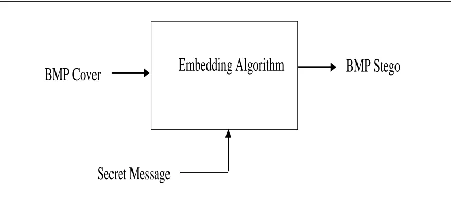
[image:30.612.125.548.224.640.2]In this study data hiding using Least Significant Bit (LSB) technique in Spatial Domain will be compared to data hiding using Discrete Cosine Transform (DCT) technique in Frequency Domain and the cover object that will be used to hide the data is cover image. Figure 3.1 below is showing the proposed framework for this dissertation.
As shown in Firgure 3.1. In order to exchange the secret message in a secure way that prevent the eavesdropper from recognizing, hacking and/or altering the stego image and the secret message the sender and the Receiver will use the Least Significant Bit (LSB) technique and Discrete Cosine Transform (DCT) technique. The Sender wants to send a secret message to the Receiver where the Attacker is the third part or the eavesdropper who wants to attack the secret message in order to change according to his/her personal proposes. To prevent the Attacker from succeeding with his/her mission and even recognizing the stego image from the other images, the proposed framework has two stages. In the first stage, the secret message is embedded in the BMP cover image by using Least Significant Bit’s embedding algorithm. then, the stego image is sent by the sender to the receiver where the receiver extracts the hiding data from the BMP stego image by using Least Significant Bit’s extracting algorithm. In the second stage, the BMP cover image is converted to JPEG and the secret message is embedded in the JPEG cover image by using Discrete Cosine Transfrom’s embedding algorithm then, the JPEG stego image is converted to BMP stego image and sent by the sender to the receiver where the receiver extracts the hiding data from the JPEG stego image by coverting back the BMP stego image into JPEG stego image and then he/she uses Discrete Cosine Transfrom’s extracting algorithm. Both BMP stego images that produced from the two technique’s embedding algorithms will be measured using Peak Signal to Noise Ratio(PSNR). section 3.2 and section 3.3 will descuss the two stage’s embedding and extracting algorithms in details.
3.2 Least Significant Bit Technique
image data can only hide 1 bit of message. Thus, 8 bytes of image data will be needed to hide 1 character because each character is made up of 8 bits. As for extracting a loop function is used until the end of the secret message is found. The Least Significant Bit’s embedding algorithm is shown in Figure 3.2 where Figure 3.3 shows the Least Significant Bit’s extracting algorithm.
[image:32.612.100.543.460.650.2]Figure 3.2: LSB embedding algorithm
Figure 3.3: LSB extracting algorithm
BMP Stego
Extracting Algorithm
Secret Message
BMP Cover
BMP Cover
Secret Message
3.3 Discrete Cosine Transform Technique
[image:33.612.115.542.322.551.2]The Discrete Cosine Transform (DCT) transforms a signal from an image representation into a frequency representation, by grouping the pixels into 8 × 8 pixel blocks and transforming the pixel blocks into 64 DCT. DCT is used in steganography as- Image is broken into 8×8 blocks of pixels. Working from left to right, top to bottom, the DCT is applied to each block. Each block is compressed through quantization table to scale the DCT coefficients and message is embedded in DCT coefficients. Figure 3.4 shows the main procedures for all encoding and message embedding processes based on the DCT where Figure 3.5 shows the procedures for all decoding and message extracting processes based on the DCT.
REFERENCES
1. Anderson, R. J., & Petitcolas, F. A. (1998). On the limits of steganography.Selected Areas in Communications, IEEE Journal on, 16(4), 474-481.
2. Anderson, R. (1996, January). Stretching the limits of steganography. In Information Hiding (pp. 39-48). Springer Berlin Heidelberg.
3. Amin, M. M., Salleh, M., Ibrahim, S., Katmin, M. R., & Shamsuddin, M. Z. I. (2003, January). Information hiding using steganography. InTelecommunication Technology, 2003. NCTT 2003 Proceedings. 4th National Conference on (pp. 21-25). IEEE.
4. Saraswat, P. K., & Gupta, D. R. (2011). A Review of Digital Image Steganography. Journal of Pure and Applied Science & Technology Copyright,2(1), 98-106.
5. General model of today’s Steganography. Retrieved on December 8 , 2013 from: http://www.datahide.com
6. Cheddad, A., Condell, J., Curran, K., & Mc Kevitt, P. (2010). Digital image steganography: Survey and analysis of current methods. Signal processing,90(3), 727-752.
7. Hemalatha, S., Acharya, U. D., Renuka, A., & Kamath, P. R. (2013). A secure and high capacity image steganography technique. Signal & Image Processing: An International Journal (SIPIJ) Vol, 4, 83-89.
8. Kaur, R., & Singh, B. (2012). Survey and Analysis of Various Steganography Techniques. International Journal of Computer Science and Advanced Technology, 6(3), 561 – 566.
9. Hamid, N., Yahya, A., Ahmad, R. B., & Al-Qershi, O. M. (2012). Image steganography techniques: an overview. International Journal of Computer Science and Security (IJCSS), 6(3), 168-187.
11.Tiwari, N., & Shandilya, D. M. (2010). Evaluation of Various LSB based Methods of Image Steganography on GIF File Format. International Journal of Computer Applications (0975–8887).
12.Grantham, B. (2007). “Bitmap Steganography: An Introduction”.
13.Fridrich, J., Goljan, M., & Hogea, D. (2003, January). Steganalysis of JPEG images: Breaking the F5 algorithm. In Information Hiding (pp. 310-323). Springer Berlin Heidelberg.
14.Provos, N., & Honeyman, P. (2003). Hide and seek: An introduction to steganography. Security & Privacy, IEEE, 1(3), 32-44.
15.Jókay, M., & Moravćík, T. (2010). Image-based JPEG steganography. Tatra Mountains Mathematical Publications, 45(1), 65-74.
16.Morkel, T., Eloff, J. H., & Olivier, M. S. (2005, June). An overview of image steganography. In ISSA (pp. 1-11).
17.Wang, S. J. (2005). Steganography of capacity required using modulo operator for embedding secret image. Applied Mathematics and Computation, 164(1), 99-116. 18.Hariri, M., Karimi, R., & Nosrati, M. (2011). An introduction to steganography
methods. World Applied Programming, 1(3), 191-195.
19.Joshi, R., Gagnani, L., & Pandey, S. (2013). Image Steganography With LSB.International Journal of Advanced Research in Computer Engineering & Technology (IJARCET), 2(1), pp-228.
20.Sutaone, M. S., & Khandare, M. V. (2008, January). Image based steganography using LSB insertion technique. In Wireless, Mobile and Multimedia Networks, 2008. IET International Conference on (pp. 146-151). IET.
21.Sravanthi, M. G., Devi, M. B. S., Riyazoddin, S. M., & Reddy, M. J. (2012). A Spatial Domain Image Steganography Technique Based on Plane Bit Substitution Method. Global Journal of Computer Science and Technology Graphics & Vision, 12 (15).
23.Shah, S. K., & Shah, D. U. (2014). Comparative Study of Image Fusion Techniques based on Spatial and Transform Domain. International Journal of Innovative Research in Science, Engineering and Technology (IJIRSET), 3(6). 24.Ouali, B. (2013). Peak Signal to-Noise Ratio. Retrieved on December 19, 2013,
From: http://www.mathworks.com
25.Bender, W., Gruhl, D., Morimoto, N., & Lu, A. (1996). Least significant bit insertion. Retrieved on April 25, 2013, From: http://www.lia.deis.unibo.it/
![Figure 2.1: General model of Steganography [5].](https://thumb-us.123doks.com/thumbv2/123dok_us/8766914.896918/15.612.116.533.360.623/figure-general-model-of-steganography.webp)
![Figure 2.2: The different embodiment disciplines of information hiding [6].](https://thumb-us.123doks.com/thumbv2/123dok_us/8766914.896918/17.612.117.539.100.281/figure-different-embodiment-disciplines-information-hiding.webp)
![Figure 2.3: Algorithm of Least Significant Bit [19].](https://thumb-us.123doks.com/thumbv2/123dok_us/8766914.896918/24.612.147.402.258.587/figure-algorithm-significant-bit.webp)
![Figure 2.5: One Dimensional DCT [22].](https://thumb-us.123doks.com/thumbv2/123dok_us/8766914.896918/26.612.159.485.136.347/figure-one-dimensional-dct.webp)
![Figure 2.6: Two Dimensional DCT [22].](https://thumb-us.123doks.com/thumbv2/123dok_us/8766914.896918/27.612.135.573.149.241/figure-two-dimensional-dct.webp)