INVESTIGATION
OF EFFECTS OF TRAILING EDGE GEOMETRY ON
VERTICAL AXIS WIND TURBINE THROUGH STRUCTURAL AND
COMPUTATIONAL FLUID DYNAMICS ANALYSIS
Harsha Vardhan Jeeru
Post Graduate Student, Department of Mechanical Engineering, Chaitanya Engineering College, affiliated to JNTUK, Andhra Pradesh, India
---***---Abstract -
Wind energy is one of the rapidly growingsources of a green energy. Moreover the wind turbines can cover a wide range of power outputs compared to other green energy sources. The design and research of low speed wind turbine blades is beneficial to the use of wind energy. The research and development of VAWT for small power applications has been increased during the last eight years. Focusing on improving the VAWT airfoil profile less attention has been paid to the significance of VAWTs to maximize the turbine performance. By considering all statements above, a small scale VAWT is designed for Local wind conditions with improvement in trailing edge shape as well. In the work herein, the effect of the trailing edge profile on the performance of the SB-VAWT is investigated and a new VAWT blade is designed for local conditions. The numerical investigation is based on the Unsteady Reynolds Navier-Stokes equations combined with the transition shear transport model. The results are validated with experimental setup done by Bravo and McLaren. Based on the predictions a local wind turbine model is designed and different trailing edge shapes, are investigated using CFD fluent based on URANS with SST model. The deformations and stresses that are developed due to fluid flow over the surface of the blade are determined using Transient structural analysis in ANSYS workbench. The two main structural vibration analyses, modal and harmonic are also done to understand the behavior of structure under various kinds of loads for different materials and designs.
Key Words:Wind turbine, Aero foil, Composites, velocity
1. INTRODUCTION
Now days, energy shortage is becoming an increasingly relevant question. The world we live in today is one of global warming, deteriorating habitats, climate change, increasing oil prices, financial crises and wars. Much of this can be attributed to the depletion and lack of oil sources, and the methods countries are using to combat. Wind power is an important source of environmental-friendly energy and has become more and more important in the recent years. The amount of installed wind power is increasing every year and many nations have made plans to make large investments in wind power in the near future. In 900 A.D first wind mills were used by Persians in sailing boats, they were Vertical Axis Wind Turbines. During the middle ages, Horizontal Axis Wind Turbines were built in Europe and used for mechanical tasks such as pumping water and grinding grains etc.
1.1Wind Turbine
A wind turbine is a rotary mechanical device that extracts energy from a wind flow and converts it into useful work. It converts kinetic energy from wind into electrical power. The wind imposes two driving forces on the blades of a turbine, lift and drag. A force is produced when the wind on the downward side of the airfoil must travel a greater distance than that on the windward side. The wind traveling on the windward side must travel at a greater speed than the wind traveling along the downward side. This difference in velocity creates a pressure differential. On the downward side, a low pressure area is created, pulling the airfoil in that direction. This is known as the Bernoulli’s principle. Lift and drag are the components of this force vector perpendicular to and parallel to the apparent or relative wind, respectively. By increasing the angle of attack, the distance that the downward air travels is increased. This increases the velocity of the downward air and subsequently the lift.
1.2 Horizontal and Vertical axis wind turbines
H-rotor is an augmented version of Darrieus turbine with straight blades instead of using curved blades. The H-rotor has variable pitch to reduce torque pulsation and is self-starting. The advantages of variable pitch are high starting torque and lower blade speed ratio, a higher coefficient of performance, more efficient operation in turbulent winds and a lower blade speed ratio which lowers blade bending stresses. H-rotor does not require any yaw mechanism system. Straight or curved blades can be used in Vertical axis wind turbine.
2. ANALYTICAL MODELLING
Table -1: List of design parameters
Category Parameter
Physical features
Blade Shape (Airfoil) Number of Blades (N) Supporting struts type and shape
Central column
Dimensional
Swept area Solidity Aspect ratio Chord/Radius ratio
Operational
Rated power output Rated wind speed Power coefficient Tip speed ratio Rotational speed
Balance of systems
Tower Braking system
Load
Others
Material Noise Aesthetic
Power Coefficient (Cp) is a measure of wind turbine efficiency often used by the wind power industry. ‘Cp’ is the ratio of actual electric power produced by a wind turbine divided by the total wind power flowing into the turbine blades at specific wind speed. When defined in this way, the power coefficient represents the combined efficiency of the various wind power system components which include the turbine blades, the shaft bearings and gear train, the generator and power electronics. The ‘Cp’ for a particular turbine is measured or calculated by the manufacturer, and usually provided at various wind speeds. If ‘Cp’ is known at a given wind speed for a specific turbine then it is easy to estimate the electrical power output.
The SB-VAWT rotor solidity (σ) is defined as the ratio of blade surface area (NcH) to the frontal swept area (2RH) that the rotor passes through.
Solidity = NC/2R Where, ‘N’ = Number of blade
‘c’ = Chord
‘H’ = Length of the blade
‘R’ = Radius of the turbine rotor.
It represents one of the key design parameters. It is evident from the definition of ‘σ’ that both the weight of the VAWT and manufacturing costs increases with increasing ‘σ’. In general, a high solidity VAWT rotor turns slowly and produces high starting torque [72]. Thus, a high solidity turbine has an advantage in producing higher torque at low tip speed ratios.
The increase in solidity has the following drawbacks:
Chart -1: Cp (vs) TSR for various solidity
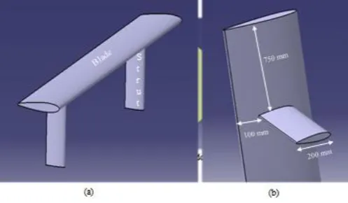
The modeling of a rotating domain consists of three blade sections and a stationary domain. It is created by using CATIA V5 R20 software. 3D single blade is modeled to carry out transient structural analysis along with modal and harmonic analysis. . The length of blade is 3750 mm with chord as 400 mm. Along with the blade two struts are created to attach the central column. Struts are created with NACA 0015 airfoil with 200 mm chord. The positions of the strut on the blade are considered from literature by which minimum deformation of the blade are taken into account. The location and dimensions are as shown in Fig 1 (a) and (b).
[image:2.595.309.558.428.573.2]
Fig -1: 3D single blade with struts
Transient analysis (sometimes called time-history analysis) is a technique used to determine the dynamic response of a structure under the action of any general time-dependent loads. This type of analysis is done to determine the time-varying displacements, strains, stresses, and forces in a structure as it responds to any combination of loads. Abbreviations used in thesis:
GWEC - Global Wind Energy Council VAWT - Vertical Axis Wind Turbine HAWT - Horizontal Axis Wind Turbine
TSR - Tip Speed Ratio
RNG - Re Normalized Group
CBT - Cyclic Butylene Terephthalate
NFC - Natural Fiber Composite
FSI - Fluid Structure Interaction
GCI - Grid Convergence Index
3. CFD ANALYSIS
Four trailing edge shapes have been implemented for the traditional NACA 0015 where the sharp trailing edge is set as the base airfoil from which trailing edge is modified into rounded and two blunt trailing edges. Rounded T.E is created with radius of 10% of the airfoil thickness and this resulted in thicker T.E in order to smooth the airfoil surface. S-blunt and R-blunt are created from cutting of 10% of the chord from rear end of sharp and rounded T.E respectively
Fig -2: 3D Trailing edge shapes
Design values for fluid domain: Length of rectangular region = 87.5C Width of rectangular region = 50C Radius of circular rotating region = 8.75C
[image:3.595.308.559.140.285.2]The Computational domain created is completely meshed by structured and unstructured 2-D Cells (triangles or quadrilaterals cells) by using edge sizing, face sizing, inflation and other refinement options in Meshingmodule of ANSYS 15.0. To differentiate both stationary and rotating domain, the two regions are imported separately from CATIA V5 to Geometric Modelling module of ANSYS as two different zones using “ADD FROZEN” option.
Fig -3: Mesh of model
[image:3.595.35.287.300.416.2]Two regions are considered one is circular rotating region which contains three equally spaced airfoils of NACA 0015 and a rectangular stationary region which surrounds the circular region.
Fig -4: Boundary conditions of fluid domain
3.1 Computational Simulation
The simulation begins with first order scheme for temporal in order to ensure stability of the simulations. Time step size of sufficiently small of order 10-3 where turbine completes one full revolution (3600) in 72 time steps and it takes 20 iterations per time step. After few revolutions higher order schemes are employed to ensure better prediction, finally turbine convergence is achieved in 6 revolutions. Convergence assessment is done when periodic torque achieves quasi- steady state called Rolling Average Convergence (RAC). Three positions has been selected to visualize and analyse the flow around the airfoils - 0⁰, 120⁰, and 240⁰.
0⁰ - flow is attached and the separation may only be present due to transition of the flow.
120⁰- Dynamic stall conditions (strong separation and vortex shedding).
240⁰ - boundary layer separation and vortex shedding settles down
[image:3.595.39.289.624.757.2]All pressure contours are similar but with a slight difference in the rounded trailing edge profile. Flow near the airfoil is attached and adverse pressure and laminar separation bubbles do not significantly affect the flow. All contours of vorticity are similar i.e. no effect of trailing edge profile plays around the airfoil.
Fig -6: Vorticity contours at 00 azimuthal angle for all trailing edges
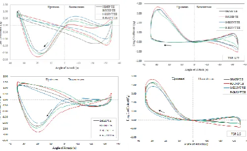
Observations of lift and drag coefficient for one turbine revolution at 1.75 and 2.5 TSR:
Lift coefficient does not change until it approaches the dynamic stall regime i.e angle of attack (α) ≤ 30⁰.
Beyond α > 30⁰ effect of T.E is clearly seen.
Downstream lift coefficient is higher for Round, Sharp, S-blunt, R-blunt T.E’s
Drag coefficient is higher for rounded one among all T.E.
For TSR=2.5, rounded T.E profile produces more lift coefficient which is peak at α = 20⁰ compared to sharp, S-blunt and R-blunt T.E
[image:4.595.40.287.167.318.2] The drag coefficient is even maximum for Round T.E in both upstream and downstream side
[image:4.595.40.290.601.753.2]Fig -7: Lift and drag coefficient at 1.75 and 2.5 TSR
Fig -8: Comparison of power coefficients
4. TRANSIENT STRUCTURAL ANALYSIS
It known that turbine performance is dependent on the material of the blade and there is fluid forces that acts on the turbine blade when it rotates, thus the blades of the turbine must have enough strength to resist the fluid forces. During this interaction of fluid and turbine blade is necessary as the blade experiences stress on its surface. One can compute this stress by performing a fluid structure interaction (FSI) analysis.
In case of a Vertical Axis Wind Turbine (VAWT) blade, the load on the blade due to the interaction of fluid changes its direction and magnitude of loads continuously in one rotation. In the present study a 3D single blade of the VAWT is considered to study the structural analysis. The blade geometry is imported from CATIA V5 into ANSYS transient structural to perform a FSI analysis. This chapter gives a detailed description of the steps involved in performing the fluid structure interaction analysis on a VAWT blade. The fluid structure interaction is done by considering the loads on the VAWT blade.
Fluid-Structure Interaction (FSI) analysis is an example of a Multiphysics problem where the interaction between two different physics phenomena, done in separate analyses, is taken into account. From the perspective of the present application, an FSI analysis consists of performing a structural in the application, with some of the loads (forces or temperatures, for example) coming from a corresponding fluid analysis or previous CFD analysis. In turn, the results of the mechanical analysis may be used as loads in a fluids analysis. The interaction between the two analyses typically takes place at the boundaries that the mechanical model shares with the fluids model. These boundaries of interaction are collectively called the fluid-structure interface. It is at this interface where the results of one analysis are passed to the other analysis as loads.
analysis (sometimes called time-history analysis) is a technique used to determine the dynamic response of a structure under the action of any general time-dependent loads. This type of analysis is done to determine the time-varying displacements, strains, stresses, and forces in a structure as it responds to any combination of loads.
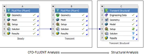
Fig -9: Fluid Structural Interaction Connection
In case of VAWT blade, the solution step in transient analysis of fluid flow fluent is connected to Transient Structural Analysis setup step as shown in Fig 6.1 to import the loads of fluid involved onto the solid 3D blade surface. Materials and its properties which are to be assigned as blade materials are entered. In the view of VAWT blade, six different materials are selected and assigned as shown in table below.
Table 2: Materialproperties
The results of transient structural analysis of round trailing edge for different materials are tabulated. The results comprise total deformation and von-Mises stresses at each and individual time steps. For the aluminium material, the maximum total deformation and maximum von-mises stress values, the maximum deformation is obtained in the middle of the blade at 1500 which is found to be 0.078 mm are shown in Fig 6.6 due to loads that are acting on the blade and also the boundary conditions. The maximum stress is obtained at 900 angular position due to max load at that particular time step (ref. table 6.2) and stress value is 3.1276 Mpa which is occurred at the tip of the strut due to fixed support.
Fig -10: Aluminium-3D VAWT Blade
The present work is of step by step procedure of transient analysis for blade by importing the load developed in the CFD analysis which is Fluid Structure Interaction. A comparative study of transient analysis is done on six different materials like aluminum 2024 which is conventional one, E glass epoxy, Flax epoxy, Jute polypropylene which are natural composites, Fiberglass polyester, Fiberglass polypropylene are synthetic composites. For all the above materials described, the transient analysis for the three different trailing edge-shapes namely Round, Gurney flap and wedge trailing edge designs are done. Transient loads developed on the blade are higher for the rounded one on comparing the deformations and stress for the three designs.
5. MODAL AND HARMONIC ANALYSIS
Modal analysis is the study of the dynamic properties of structures under vibrational excitation. It is an important tool in vibration analysis and diagnosis. The primary and most important objective of modal analysis is to determine the natural frequencies and mode shapes of the test structure. A resonance condition exists when the frequency of excitation due to any source coincides with a natural frequency of the test structure. Therefore it is necessary to know the natural frequencies of the test structure to be monitored prior to the experimentation.
In the course of designing the blade, vibration has to be considered as it is important to avoid dynamic instability in
the form of resonance. Resonances cancause fatigue damage
and rapid failure. Deformation patterns (bending, twisting.) at these resonant frequencies take on a variety of different shapes depending on the excitation force frequency. In this chapter, the detailed description is given on modal analysis of vertical axis wind turbine by using ANSYS software.
5.1 Procedure for modal analysis in ANSYS
The following steps are followed for modal analysis
Importing 3D CATIA wind turbine single blade
model
Defining the material properties
Mesh generation
Applying boundary condition.
Solving the problem
Reporting results
No Material
Volu me Fract
ion (%)
Young’ s Modulu s (GPa)
Yield Strengt h (MPa)
Densi ty (kg/
m3)
Poiss on Ratio
1 Aluminium - 2024 - 73 620 2780 0.320
2 E - Glass Epoxy 55 70 2000 1900 0.280
3 Flax Epoxy 46 35 280 1400 0.360
4 PolypropyleJute
ne 60 11 74 1460 0.396
5 Fiberglass
Polyester 30 6.9 86 1356 0.325
6 PolypropyleFiberglass
[image:5.595.39.285.165.257.2]5.2 Results of Modal Analysis
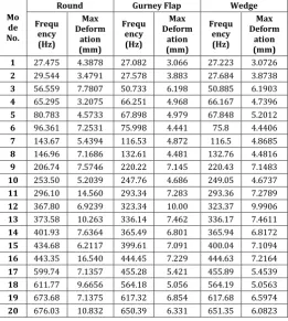
[image:6.595.315.554.274.366.2]The six types of materials are applied to this wind turbine blade .Various modes of vibration of wind turbine blade model are observed. The first twenty natural frequencies and their mode shapes are generated for Aluminium 2024, E-Glass epoxy, Flax Epoxy, Jute polypropylene, Fiber Glass polyester, Fiberglass polypropylene of wind turbine blade at free load for round trailing edge geometry with fixed struts as boundary condition. The same procedure is repeated for the remaining gurney flap and wedge trailing edges. The mode shape frequencies and its corresponding deformation for the Aluminium material are given in Table 7.1 which are resulted from modal analysis by using ANSYS software
Table 3: Pressure contours at 00 azimuthal angle for all trailing edges
Mo de No.
Round Gurney Flap Wedge
Frequ ency (Hz)
Max Deform
ation (mm)
Frequ ency (Hz)
Max Deform
ation (mm)
Frequ ency (Hz)
Max Deform
ation (mm)
1 27.475 4.3878 27.082 3.066 27.223 3.0726
2 29.544 3.4791 27.578 3.883 27.684 3.8738
3 56.559 7.7807 50.733 6.198 50.885 6.1903
4 65.295 3.2075 66.251 4.968 66.167 4.7396
5 80.783 4.5733 67.898 4.979 67.848 5.2012
6 96.361 7.2531 75.998 4.441 75.8 4.4406
7 143.67 5.4394 116.53 4.872 116.5 4.8685
8 146.96 7.1686 132.61 4.481 132.76 4.4816
9 206.74 7.5746 220.22 7.145 220.43 7.1483
10 253.50 5.2039 247.76 4.686 249.05 4.6737
11 296.10 14.560 293.34 7.283 293.36 7.2789
12 367.80 6.9239 323.34 10.00 323.37 9.9906
13 373.58 10.263 336.14 7.462 336.17 7.4611
14 401.93 7.6364 365.49 6.801 365.94 6.8172
15 434.68 6.2117 399.61 7.091 400.04 7.1094
16 443.35 16.540 444.45 7.229 444.63 7.2164
17 599.74 7.1357 455.28 5.421 455.89 5.4539
18 611.77 9.6656 564.18 5.056 564.19 5.0563
19 673.68 7.1375 617.32 6.854 617.68 6.5974
20 676.03 10.832 650.39 6.331 651.35 6.0823
5.3 Procedure for harmonic analysis in ANSYS
For harmonic analysis the following steps has to be followed:
Importing the geometry from CATIA.
Feeding the Material properties.
Mesh the wind turbine blade.
Applying boundary conditions and the loads
Set frequency range
Solve the problem
5.4 Results of Harmonic Analysis
[image:6.595.31.293.296.588.2]The harmonic response of wind turbine blade for materials Aluminium 2024, E-Glass epoxy, Flax Epoxy, Jute Polypropylene, Fiber Glass Polyester and Fiber Glass Polypropylene are analysed using harmonic analysis for different trailing edges. The harmonic force is considered from transient analysis i.e. maximum deformation load in a complete revolution of turbine on blade. For round trailing edge profile geometry, the harmonic force of magnitude Fx = 834.16 N, Fy = 14.01 N is taken as input and the range of frequencies are defined from respective modal analysis. For Gurney Flap and wedge trailing edge profile geometry VAWT blade, harmonic input is considered accordingly and results are tabulated below along with round trailing edge.
Fig -11: Results of Harmonic analysis for Round trailing edge of NACA 0015
The modal analysis is done for three trailing edge shapes namely Round, Gurney Flap and Wedge using ANSYS workbench. However for each trailing edge model, six different materials of which conventional, synthetic and natural composites are considered for analysis. From the modal analysis, the first twenty natural frequencies and mode shapes are identified for individual materials for the three trailing edge shapes and also range of frequencies are noted. It is observed that for Flax Epoxy and Aluminium 2024 range of frequencies are high and similar where lower range frequencies are identified for other materials. Furthermore harmonic analysis is done for all three trailing edge shapes to observe the response of blade under harmonic load for each material is studied.
4. CONCLUSIONS
turbine. From modal and harmonic analysis, it is concluded that the mode shapes obtained for Round, gurney Flap and wedge are different due to changes in mass distribution of geometry. Six different materials of traditional, synthetic and are selected to blade material and for these the first twenty modes shapes are obtained and noted the resonance frequencies. Furthermore, harmonic analysis is carried out to study the behavior under fatigue loads. It is concluded that the blade materials chosen can bear the loads as the deformations and stresses are below the design criteria
.
The designed 3D single VAWT straight blade which is extruded NACA 0015 airfoil section using CATIA V5 is saved in .IGES format and imported. The struts of VAWT blade are also done using NACA 0015 airfoil section. The model is meshed with tetrahedral elements forming 14516 nodes and 7272 elements of 3D blade.REFERENCES
[1] “World Wind Energy Report 2015". Report. "World
Wind Energy Report 2008”Physical Progress (Achievements)". Ministry of New and Renewable Energy, Govt. of India.31 July 2017. Retrieved 19 September 2016 Manwell JF, McGowan JG, Rogers AL. Wind energy explained, 1st ed. Amherst, USA: Wiley; 2002Science, 1989.
[2] Reuter RC, Worstell MH, “Torque ripple in a vertical axis
wind turbine”. Sandia National Laboratories.
[3] Vandenberghe D, Dick E, “A free vortex simulation
method for the straight bladed vertical Axis wind turbine” J Wind Eng Ind Aerodyne; 26:307–24, 1987.
[4] Tucker VA, “Using a collision model to design safer wind