© 2017, IRJET | Impact Factor value: 5.181 | ISO 9001:2008 Certified Journal | Page 2039
MODELING AND ANALYSIS OF AUTOMOBILE CHASSIS USING
COMPOSITE MATERIALS
MD AZHAR KAZMI
1, Mr. V. SUNIL
2, Mr. S.UDAYA BHASKAR
31
P.G. Scholar,Machine Design, Al-Habeeb Colleg of Engineering Technology (J,N.T.U.H)
2Asst.Prof.M.Tech. Mech. Dept., Al-Habeeb Colleg of Engineering Technology (J.N.T.U.H)
3Asso. Prof, M.Tech (Ph.D), Mech. Dept., Al-Habeeb Colleg of Engineering Technology (J.N.T.U.H)
---***---ABSTRACT: In this analysis describes design and analysis
of automobile chassis. Model of chassis is done in Pro-E software and is imported to ANSYS. The model is meshed. The material properties are defined in pre-processing. Initially static analysis has done on the chassis using different materials, and then the modal analysis was done to obtain the mode shapes of the chassis. Its principle function is to undamaged carry the maximum load for all designed operating conditions. An automobile chassis consists of a framework which supports a man-made object. It is same as an animal's skeleton. The chassis is a skeletal frame in which various automobile parts like engine, axle, tires, assemblies, steering, brakes etc. are affixed. Chassis is considered as a most important component of an automobile. It is the most vital element that provides strength and stability to the vehicle under different situation. It is provide strength and flexibility to it.
Key Words: Composite Material, Automobile Chassis, F.E.A ,Pro/E, ANSYS.
1
. INTRODUCTION
An automobile chassis consists of framework which supports a man-made object vehicle is built on. It is like to an animal's skeleton. For an example of an automobile chassis is the inner part of an automobile, consisting of the frame on which the automobile body is mounted with the machinery and wheels. Automotive framework is a structure on which various automobile parts are bolted, like engine, axles, tires assemblies, steering, brakes and other automobile accessories etc. The automobile chassis is considered to be the most important parts of an automobile. Chassis is the most essential element of an automobile that provides strength and stability to the automobile under different situation. Automobile chassis afford strength and flexibility of the vehicle. The chassis to be backbone of an automobile, And chassis is the supporting frame the body of an engine, axle assemblies are affixed together. The Tie bars, that is necessary parts of the automotive frames, are that bind various automobile parts together.
2.
THE SOME VARIOUS TYPES OF AUTOMOBILE
CHASSIS IS FOLLOWING
a. Ladder Chassis b. Backbone Chassis c. Monocoque Chassis3 MATERIALS
USED
FOR
CHASSIS
MANUFACTURING
Traditionally, the most common material selection for manufacturing vehicle chassis would be steel, in various forms. Some time, other materials have come into use, the majority of which have been covered here.
3.1
Steel
Steel is easy to get. Machinery to manipulate steel is easy to get. People who know how to work with steel are easy to get. Steel is easy - and it's also cheap. This is the main reason why 99% of the cars you find are made from steel
3.2
Titanium
Titanium has an association with space tech, and is regarded by many people as an "ultimate" material. It has a density roughly half that of steel.
3.3
Magnesium
Magnesium is the lightest metal that's likely to be used in a vehicle chassis, with a density about quarter that of steel. This weight advantage helps to compensate for the fact that its strength and rigidity is below even aluminium.
3.4
Fibreglass
Raw plastics do not have anywhere near enough stiffness to be used for structural components in cars. If strands of glass are added to the mixture, though, their properties improve remarkably.
3.5
Carbon Fibre
© 2017, IRJET | Impact Factor value: 5.181 | ISO 9001:2008 Certified Journal | Page 2040 Plastic (CFRP/CRP), though almost everyone refers to it as
simply "carbon fiber".
4. MODELLING OF CHASSIS
Generally, during modling of an automobile chassis using the following method.
4.1
Modeling Of Chassis Using CAD System.
There are some good reasons for using a CAD system to support the mechanical design function:
To increase in the productivity.
To get better the quality of the mechanical design. To uniform design standards. To create a
manufacturing data base.
To remove inaccuracies due to hand-copying of drawings and irregularity between Drawings.
4.2
Using Pro/Engineer
Pro/ENGINEER is the industry of standard 3D mechanical design uniform. It is the world’s leading CAD/CAM/CAE software, provide a wide range of integrated solutions to cover all form of product design and manufacturing.
Advantages of Pro/Engineer
It is too fast and more in accuracy. If a design is finished. 2D and 3D views are ready to obtain. It has ability to incorporate changes in the design
process is also possible.
It is provides very accurate in representation of model specifying all other dimensions hidden geometry etc.
It provides a better flexibility for change. For example if we like to change in dimensions of our model, all the related dimensions provide in design assembly, manufacturing etc. will be automatically changed.
It give clear 3D models, which are easy to visual inspected and understand.
Pro/E provides simple assembly of the models or individual parts created it also less time required for the assembly to a large amount
Parts To Model
Part no Description QTY
1 Main Channel 2
2 End Channel 1
4 Support Channel 5
Table No. 1
[image:2.595.309.559.103.295.2]4.3
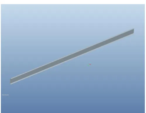
3D Drawings using pro-E
[image:2.595.309.559.332.525.2]Figure 1. MAIN CHANNEL
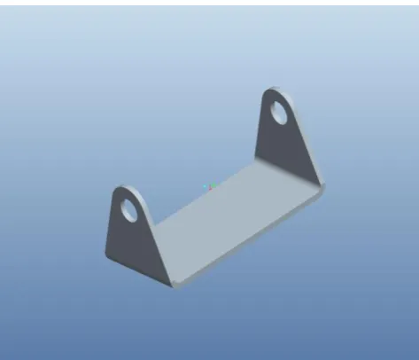
Figure 2 SUPPORT CHANNEL
Figure 3. SUPPORT CHANNEL
© 2017, IRJET | Impact Factor value: 5.181 | ISO 9001:2008 Certified Journal | Page 2041 Figure 4. HINGE
Figure 5. ASSEMBLY
Require chassis has been design using pro-e and saved as “.asm “.
5. FINITE ELEMENTS ANALYSIS
The main concept in Finite Element Analysis is that the structure or body may be divided into small elements of finite dimensions is called “Finite Elements”. The original structure or the body is then considered as an assembly of these elements associated at a finite number of joints called is “Nodes point” or “Nodal”. Simple functions are chosen to estimated the displacements of every finite element. Such assumed functions are called “shape functions”. This will represent the displacement with in the element in terms of the displacement at the nodes of the element.
The finite element method (FEM) is a most important tool for which concerned in engineering design; it is now used regularly to solve the problems in the given below areas:
Structural analysis
Thermal analysis
Vibrations and Dynamics analysis Buckling analysis
Acoustics
Fluid flow simulations Crash simulations Mold flow simulations
6.1
INTRODUCTION TO ANSYS
The ANSYS application is self contained common purpose finite element program developed and maintain by Swason.
ANSYS Finite Element Analysis software has ability to engineers Design to analyze the following tasks:
Transfer CAD models of structures or, products, systems or build computer models components. Apply the operating loads and other design
performed conditions.
Study the physical activity response, such as temperature distributions, stress levels, and electromagnetic fields.
Optimize a designing early in the development process to minimize production costs.
Perform prototype testing in environments where it would be undesirable or impossible.
For users easy, simply access to program functions, documentation commands, and reference material, The ANSYS program have a compressive graphical user interface (GUI) .A perceptive menu system helps the users to operate through the ANSYS Program.
6.2
MODEL ANALYSIS
Modal analysis is the method to determine a structure and dynamic characteristics, are listed below,
Resonant frequencies. Damping values and
The associate with the pattern of structural deformation is called mode shapes.
6.2.1 Uses of Modal Analysis
To find out the mode shapes of a structure and natural frequencies, Modal analysis is needed. The natural frequencies and mode shapes are the essential parameters to design a structure for dynamic loading conditions.
7. RESULTS AND DISCUSSION
© 2017, IRJET | Impact Factor value: 5.181 | ISO 9001:2008 Certified Journal | Page 2042 Sl.
No Properties Units Steel Carbon Epoxy E-Glass Epoxy
Rub ber
1 Young’s Modulu s E11
N/ mm2
2.068
e11 1.34 e 11 50 e 9 4
2 Density kg/ m3 7830 1600 2000 2466
[image:4.595.22.543.46.813.2]3 Poisson Ratio - 0.3 0.3 0.3 0.49
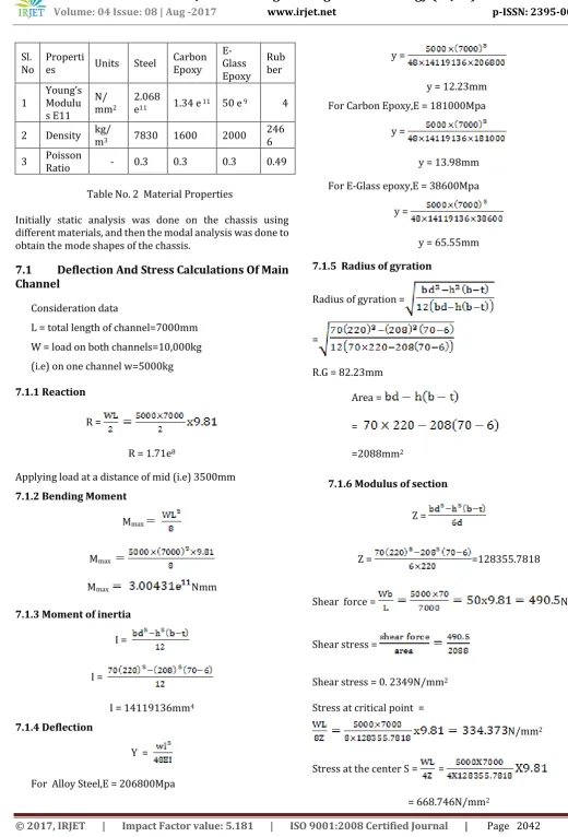
Table No. 2 Material Properties
Initially static analysis was done on the chassis using different materials, and then the modal analysis was done to obtain the mode shapes of the chassis.
7.1
Deflection And Stress Calculations Of Main
Channel
Consideration data
L = total length of channel=7000mm W = load on both channels=10,000kg (i.e) on one channel w=5000kg
7.1.1 Reaction
R =
R = 1.71e8
Applying load at a distance of mid (i.e) 3500mm 7.1.2 Bending Moment
Mmax
Mmax
Mmax Nmm
7.1.3 Moment of inertia
I =
I =
I = 14119136mm4
7.1.4 Deflection
Y =
For Alloy Steel,E = 206800Mpa
y =
y = 12.23mm For Carbon Epoxy,E = 181000Mpa
y =
y = 13.98mm
For E-Glass epoxy,E = 38600Mpa
y =
y = 65.55mm
7.1.5 Radius of gyration
Radius of gyration =
=
R.G = 82.23mm
Area =
=
=2088mm2
7.1.6 Modulus of section
Z =
Z = =128355.7818
Shear force = N
Shear stress =
Shear stress = 0. 2349N/mm2
Stress at critical point =
N/mm2
Stress at the center S = =
© 2017, IRJET | Impact Factor value: 5.181 | ISO 9001:2008 Certified Journal | Page 2043
7.2 Structural And Modal Analysis Of Chassis
Without Damping Material And Layers
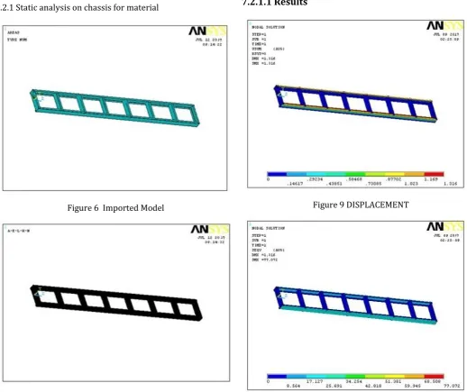
The pro-E model is imported to ansys. The material taken as steel, youngs modulus, poisson ratio and density are given. Finite element simulation of chassis designed.
Complete the study about chassis design, analysis of the chassis, existing data and compotator modal. 3D finite models of a chassis to simulate static
structural of FE analysis were developed
FE meshed model is developed for obtain accurate results.
The stress concentration areas were evaluated by the finite element analysis. From the analysis, it was obtained that the stress concentration areas be distributed at the rear of rail structure and horse collar portion of the chassis.
Figure 6 Imported Model
[image:5.595.310.564.88.287.2]Figure 7 Meshed Model Pressure – 0.06N/mm2
Figure 8 Loads acting on the chassis
[image:5.595.40.559.323.758.2]7.2.1.1 Results
Figure 9 DISPLACEMENT
© 2017, IRJET | Impact Factor value: 5.181 | ISO 9001:2008 Certified Journal | Page 2044 Figure 11 SHEAR STRESS IN XY
7.3
CONCLUSION
Chassis used in a heavy vehicle modeled using Pro/Engineer. Structural and modal analysis is done on the automobile chassis using ANSYS software. This analysis is done using three materials which is STEEL, CARBON EPOXY and E-GLASS EPOXY. Using different layers 3, 5 and 11 with and without damping material as RUBBER.
To observing the structural analysis results, the stress values of Carbon Epoxy and E –Glass Epoxy are less than their permissible stress values. So using this composite for chassis is safe. To using composites alternative of steel, the weight of the chassis reduces by 4 times than alternative using of steel because the density of steel is more than to the composites.
By using the layers for maintain same thickness of the chassis, and the displacement as well as stress values are reduced than using as single layer. So it will be better to take layers as single layer
7.4
Future Scope
There is a high scope for further research in chassis simulation to solve vibration, frequency response and mode shape analysis related problems.
Useful future work would be to find out torsional stiffness of the chassis including the modeling infinite springs, suspension, and loading.
This chassis structure should be further analysed and improved on the overall performance especially on structural dynamic behaviour and quality auditing for better
8 REFERENCES
"Mechanics of Composite Materials", Autar K. Kaw, CRC press, 1997.
“Vibration Damping”, Ahid D. Nashif, David I. G. Jones and John P. Henderson, John Wiley & Sons Publication, 1985, Newyork.
“Damping Performance of Cocured Composite Laminates with Embedded Viscoelastic Layers”, J. M. Biggerstaff and J. B. Kosmatka, Journal of Composite Materials, Vol. 32, No.21/ 1998.
"Vibration Damping of Structural Elements", C. T. Sun and Y. P. Lu, Prentince Hall PTR, New Jeresy, 1995.
"Dynamics of Viscoelastic Structures K. J. Buhariwala and J. S. Hansen, ", AIAA Journal, Vol. 26, February 1988, pp 220-227.