© 2018, IRJET | Impact Factor value: 6.171 | ISO 9001:2008 Certified Journal | Page 4803
Design & Analysis the parameters of strain based FBG sensors using
Optigrating
Azhar Shadab, Nagma Jurel, Priya Sarswat,
1Assistant Professor, Department of ECE, Anand Engineering College-Agra,282007 2 Student, Department of ECE, Anand Engineering College-Agra,282007
---***---ABSTRACT:
Fiber Bragg Grating is the one of the mostcommercially used techniques for making high accuracy sensors and these FBG based sensor is based on the principle of Bragg wavelength, These days FBG is very efficient for tracking the fault detection of any parameters like stress, pressure, strain, temperature, vibration, etc of any system. FBG works with the grating length selection and relative effective wavelength. In this paper our focus is to simulate and analyze the some parameters of FBG like Stress and strain and this simulation is done by using OptiGrating 4.2 version. OptiGrating is used to work with the couple mode theory where forward and backward propagation waves can easily analyzed. This paper helps for designing the sensing application which is based on stress and strain parameters.
Keywords:-Fiber Bragg Grating, Strain , OptiGrating, FBG Sensor
1. INTRODUCTION
Fiber Bragg grating is one of the most key optical components, which are gaining attention in different fields of optical fiber communication and sensing applications. A fiber Bragg grating (FBG) is a type of distributed Bragg reflector constructed in a short segment of fiber that reflects particular wavelengths of light and transmits all others. This is achieved by adding a periodic variation to the refractive index of the core of the fiber, generating a wavelength specific mirror. The use of the fiber Bragg grating as the dispersion compensation element made revolutionary developments in the field of fiber optic communication. The Bragg wavelength as a function of grating pitch also made it possible to build transducers for precisely measuring many physical quantities like strain, temperature, acceleration etc [2][5]. Fiber Bragg gratings are used two types of grating firstly short period grating and another long period grating. Short period grating are also refer as fiber Bragg grating because the phenomena equivalent to Bragg reflection and Bragg deflection crystal.
When the light beam is incident in the core because of index contrast a part of beam reflected from this interface ,the beam goes out and that it reflected from the real interface similarly all other layer, there would be reflection. When all these reflections are added up in phase that they can have a very strong reflection and this will have at a particular reflection [1].
2.EXPRESSION OF FBG FOR COUPLE MODE THEORY
In fiberBragg grating a wave is incident at a periodicity Λ continuous that divided by 2 for high reflective region and Λ/2 for low reflective region. High refractive index n0+Λn0and for low refractive index isn0 –Λn0. If all the wave
reflection added up in phase and they have a phase shift of 2π and integral multiple of 2π then have a strong reflection[3]. The wavelength for fiber which the incident light is reflected with maximum efficiency is called the Bragg wavelength. In optical fiber condition is given by
=2π/Λ ………... (1)
Where β1 and β2are propogation constant and Λ is grating
period.
Therefore phase matching condition ,
( ) ………...1.2
Since Δβ is large ,
………..1.4
© 2018, IRJET | Impact Factor value: 6.171 | ISO 9001:2008 Certified Journal | Page 4804 Fig.1 Basic operation of the FBG [4]
Fig.2 Basic structure of Fiber Bragg Grating [2]
Fresnel reflection is the basic principle behind the operation of a FBG. Where a light traveling through media of different refractive indices may both reflect and refract at the interface. The grating will typically having a sinusoidal refractive index which varied over a defined length. The reflected wavelength (λ B), called the Bragg
wavelength, is defined by this equation,
………... (2)
Where ‘n’ is the effective refractive index of the grating and Λ is the grating period. In this case n=(n2+n3)/2 , i.e. it is
the average refractive index in the grating (see Fig. 2). The wavelength spacing between the first minimums (nulls), or the bandwidth (Δλ), is given by,
………. (3)
Where δn0 is the variation in the refractive index (n3 −n2),
and η is the fraction of power in the core.
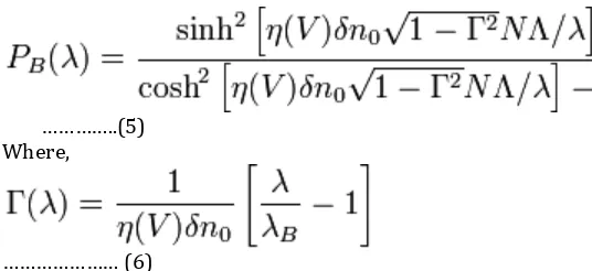
The peak reflection (PB (λ B)) is approximately given by
……… (4)
[image:2.612.54.525.92.577.2]© 2018, IRJET | Impact Factor value: 6.171 | ISO 9001:2008 Certified Journal | Page 4805
…………..(5) Where,
……… (6)
The structure of the FBG can vary through the refractive index, or by grating period. The grating period can be uniform or graded, and either localized or distributed in a superstructure. The refractive index has two primary characteristics, the refractive index profile, and the offset. Typically, the refractive index profile can be uniform or apodized and the refractive index offset is positive or zero. There are six common structures for FBGs;
1. Uniform positive-only index change
2. Gaussian apodized
3. .Raised-cosine apodized
4. Chirped
5. Discrete phase shift
6. Superstructure
3.FBG AS A STRAIN SENSOR
Fig.3. FBG strain sensor
When a strain is applied to a FBG, it causes the physical elongation of the optical fiber and due to the photo elastic effect the grating pitch and the refractive index of fiber changes. As a result the shift in Bragg wavelength occurs. The shift in wavelength
ΔλB=(1-Pe) λBε ………….………(7)
Pe = (n2 /2)[P12-μ(P11+P12)]
………….………7.1
Parameters Symbols Values
Bragg wavelength λB 1.55μm
Core width L 4.15μm
Effective refractive
index neff 1.47
Grating manager L,H,P 4000,0.002,450
6 .RESULT AND ANALYSIS
1.INPUT
5.
SOFTWARE ANALYSIS(OPTIGRATING)Optigrating is a user friendly and powerful software for integrated many parameters. The operation of many sensors and telecommunication devices based on optigrating .For example, waveguide grating technology has been used in WDM optical networks, laser stabilization, and temperature and strain sensing. A grating-assisted device can be analyzed and designed by calculating light propagation, reflection and transmission spectra, the phase group delay, and the dispersion. While the calculation results depend on waveguide and grating parameters, the design task can be greatly facilitated by the use of the appropriate computer
where Pij are Pockel’s coefficients of the strain optic
sensor. μ is the poission ratio of the optical fiber. Where ε is the applied strain. Pe is the photo elastic coefficient term.
The measured strain response at a constant temperature is found to be (1/λB)[dλB/ dε] = 0.78 x 10⁻⁶με-1 .
The measured temperature response at a constant strain is found to be (1/λB)[dλB/ dT] = 6.67 x 10⁻⁶ oC-1 .
[image:3.612.35.303.80.203.2]© 2018, IRJET | Impact Factor value: 6.171 | ISO 9001:2008 Certified Journal | Page 4806
2.INPUT SPECTRUM
3.GRATING SPECTRUM
4. SINGLE FIBER MODE
5.SINGLE MODE FIBER(CLADDING)
6.GRATING MANAGER
7.PROPOGATION POWER
8.PROPOGATION SCAN
© 2018, IRJET | Impact Factor value: 6.171 | ISO 9001:2008 Certified Journal | Page 4807
10.PULSE RESPONSE INPUT SPECTRUM
11.PULSE RESPONSE GRATING SPECTRUM
12.PULSE RESPONSE OUTPUT
13.PULSE RESPONSE SCAN
14.SPECTRUM DELAY
15.SPECTRUM DISPERSION
16.SPECTRUM PHASE
17.SPECTRUM POWER
18.SPECTRUM SCAN
© 2018, IRJET | Impact Factor value: 6.171 | ISO 9001:2008 Certified Journal | Page 4808
20.CALCULATE INPUT SPECTRUM
21.CALCULATE GRATING SPECTRUM
22.CALCULATE OUTPUT
23.CALCULATE GRAPH
24.CALCULATE SCAN
25.CALCULATE PROFILE
26.INPUT
© 2018, IRJET | Impact Factor value: 6.171 | ISO 9001:2008 Certified Journal | Page 4809
28.SINGLE MODE FIBER(CORE)
29.SINGLE MODE FIBER(CLADDING)
30.GRATING MANAGER
31.PROPOGATION POWER
32.PROPOGATION SCAN
33.PULSE RESPONSE INPUT
34.PULSE RESPONSE INPUT SPECTRUM
© 2018, IRJET | Impact Factor value: 6.171 | ISO 9001:2008 Certified Journal | Page 4810
36.PULSE RESPONSE OUTPUT
37.PULSE RESPONSE SCAN
38.SPECTRUM DELAY
39.SPECTRUM DISPERSION
40.SPECTRUM PHASE
41.SPECTRUM POWER
42.SPECTRUM SCAN
43.CALCULATE INPUT
44.CALCULATE INPUT SPECTRUM
© 2018, IRJET | Impact Factor value: 6.171 | ISO 9001:2008 Certified Journal | Page 4811
46.CALCULATE OUTPUT
47.CALCULATE SCAN
48.CALCULATE PROFILE
From the above FBG results, it can be easily analyze that the selected parameters can be used for different applications and this is done with the help of simulation technique by optigrating software, The following grating options chosen by authors which is as follows
1.Average Index-- linear ,uniform, from file, or user defined function.
2.Grating The selection of grating is based on Chirp—sine ,rectangular from file, or user defined function.
3.period chirp—Quadratic, linear , square root, cubic root, from file or user defined function.
4.Adjustable parameters—length, index modulation, or height, order, tilt angle, index modulation.
6.CONCLUSION
Fiber Bragg Grating having reflectivity increases that increase in grating length and index modulation.FBG having bandwidth is narrower for longer grating length and wider for index modulation. When increase in grating period, Bragg wavelength shift from central wavelength . This change having in wavelength shift can be used for strain and temperature sensors. From all the above results it is very clearly analyze that the considering parameters shows the characteristics of FBG parameters which is very helpful for vibration, Temperature, Strain, Stress , medical sensors etc.
7.REFERENCES
[1] Chiranjit Ghosh, Quazi Md. Alfred, Biswajit Ghosh,“Spectral Characteristics of Uniform Fiber Bragg Grating With Different Grating Length and Refractive Index Variation’’, International Journal of Innovative Research in Computer and Communication Engineering (IJIRCCE), Vol.3, Issue.01, January 2015.
[2] Arora, Dinesh, Jai Prakash, Hardeep Singh, Amit Wason,‘‘Reflectivity and Braggs wavelength in FBG’’, International Journal of Engineering (IJE), Vol.5, Issue.05, 2011.
[3] Deba Kumar Mahanta,‘‘Design of Uniform Fiber Bragg grating using Transfer matrix method’’, International Journa of Computational Engineering Research (IJCER) Vol.3 , 2013.
[4] K. O. Hill, Y. Fujii, D. C. Johnson, and B. S. Kawasaki, “Photosensitivity in optical fiber waveguides: Application to reflection filter fabrication,” Appl. Phys. Lett., vol. 32, pp. 647–649, 1978.
[5] B. S. Kawasaki, K. O. Hill, D. C. Johnson, and Y. Fujii, “Narrow-band Bragg reflectors in optical fibers,” Opt. Lett.,
![Fig.2 Basic structure of Fiber Bragg Grating [2]](https://thumb-us.123doks.com/thumbv2/123dok_us/8136287.798370/2.612.54.525.92.577/fig-basic-structure-fiber-bragg-grating.webp)