© 2017, IRJET | Impact Factor value: 5.181 | ISO 9001:2008 Certified Journal | Page 456
DYNAMIC ANALYSIS OF STEEL MOMENT RESISTING FRAME ON SLOPING
GROUND WITH BRACINGS AND SHEAR WALL
Sanjay S D
1, Supreeth S
21
P.G. Student, Civil Engineering Department, Sri Jagadguru Balagangadharanatha Institute of Technology,
Bengaluru - 560060, Karnataka, India
2
Assistant Professor, Civil Engineering Department, Sri Jagadguru Balagangadharanatha Institute of Technology,
Bengaluru - 560060, Karnataka, India
---***---Abstract -
India is one of the developing country, caused
scarcity of land because of industrialization and urbanization; therefore there has been considerable increase in construction of multistory buildings in hilly areas.The buildings situated on hill slopes in earthquake prone areas are generally irregular, torsionally coupled & hence, susceptible to serve damage when affected by earthquake ground motion. Such buildings have mass & stiffness varying along the vertical & horizontal planes, resulting the center of mass & center of rigidity do not coincide on various floors, hence they demand torsional analysis, in addition to lateral forces under the action of earthquakes. These unsymmetrical buildings require great attention in the analysis & design. Analysis of hill buildings is somewhat different than the buildings on leveled ground, since the column of hill building rests at different levels on the slope. The various floors of such buildings step backs towards hill slope and at the same time buildings may have setbacks also. It is observed that the seismic behaviour of buildings on sloping ground differ from other buildings. Most of the studies agree that the buildings resting on sloping ground has higher displacement and base shear compared to buildings resting on plain ground and the shorter column attracts more forces & undergoes damage, when subjected to earthquak.
In this work, building in the sloping ground need to be make considered in order to make exists as of when all the maximum storey drift occured, computed with all the design eccentric condition in a high rise structures, at another end the structures with transverse to all an axis which will be of more than 1.2 times the average storey drifts at par the two ends of the building. Here our aim is to make understand the importance of codal provision which will be in particularly suggesting the bracing provision for high rise buildings. 6 numbers of different types of twelve storied RC framed and RC framed with shear wall buildings in the sloping grounds are considered. Dynamic analysis has been performed by Response Spectrum Method for all the different seismic zones and for all the soil conditions. Variations of the result of all the structural elements are
been studied in a detail manner for all other different parameters.
.
Key Words
: Sloping Ground, Bracings,
Shear Wall,
Story Shears, story drifts,Story Displacements.
1.INTRODUCTION
Seismology is a concept in which the study of all the vibrations of earth will be done, which is mainly caused due to the earthquakes. The structural element resisting all the lateral forces available which will be acting and will be due to the seismic and the wind loading conditions and the shear walls or with the bracings in which it will be provided in order to make resist all the available lateral sway conditions and it will be much more susceptible to the damage that will be causing when it was affected by the ground motions. Shear walls are one in which it will be the most commonly available by the lateral load resisting systems in the tall structure.
Shear wall which is of high in the plane stiffness conditions and the strength considerations which will be used in order to make the simultaneously in order to make resist all the larger horizontal and the dead loads. So that there will be much in order to make study all the shape and the locations of the shear walls and also with the bracings on to the seismic performances of the building which will be located on a sloping grounds.
© 2017, IRJET | Impact Factor value: 5.181 | ISO 9001:2008 Certified Journal | Page 457 Fig-1: Building in sloping ground
1.1 Objectives Of The Study
Here building in the sloping ground need to be make considered in order to make exists as of when all the maximum storey drift occurred , computed with all the design eccentric condition in a high rise structures, at another end the structures with transverse to all an axis which will be of more than 1.2 times the average storey drifts at par the two ends of the building. Here our aim is to make understand the importance Of type codal provision which will be in particularly suggesting the bracing provision for high rise buildings. 6 numbers of different types of twelve storied RC framed and RC framed with shear wall buildings in the sloping grounds are considered. Dynamic analysis has been performed by Response Spectrum Method for all the different seismic zones and for all the soil conditions. Variations of the result of all the structural elements are been studied in a detail manner for all other different parameters.
1.2 Limitations Of The Study
Our present study which will be mainly focus on the building on the sloping grounds effects of a different high rise structures, and all the structural modeling is carried out with only a shear walls. However in order to compute its real behaviour of the structure, FEM method can be adopted with a frames and different types of the shear walls and the interface elements is recommended.
In Our study was not considered during our analysis of
the structures. Bases with a fixed conditions will be made assumed for our analysis process of the columns in our present study, however it is to be noted that the torsional responses will be much increased because of all the foundational movements. This will be a aspect which is not considered and will be not studied.
In our present study, seismic analysis will need to be carried with in its elastic limits. However the behavior of the structure due to the torsional irregular condition structures are too often highly complex in nature in its elastic limit ranges and that need to be further investigated by make it carrying the inelastic type analysis of the structure.
2. MODELING
For design and analysis we are using ETABS version 9.7.4 features a powerful graphical user interface system and design mechanisms.
The most common method of forming a different kind of structure is included in the simplest process. The basic model was first created and then other configurations will be updated to different models. Here we are presenting 5 different patterns.
1. Type A – regular model in sloping ground with bracings. 2. Type B – regular model in sloping ground with shear wall.
2.1 Model Design Of Type A and B
In our model, the structure as ductile shear wall with SMRF. Number of stories as G+30 and each storey height 3.0m. Foundation type as isolated footing and seismic zone Z-3.
2.2 Materials Properties
Grade of concrete M30 and grade of steel Fe500. Slab thickness 200mm , Beam size as ISMB600 , column size as built up section and thickness of shear wall 200mm.
Dead load intensity roof finishes 1.5 KN/m2 and floor finishes 1.5 KN/m2
© 2017, IRJET | Impact Factor value: 5.181 | ISO 9001:2008 Certified Journal | Page 458 Fig-3: ETABS model of type – A, 30 storied building
Fig-4: ETABS model screen shot of Type – B, 30 storied building
3. ANALYSIS RESULTS AND DISCUSSIONS
3.1 Model Analysis part of type A and type B
Modal analysis is carried out to understand the dynamic behaviour of structures under different modes. Time period in seconds and frequency for all steel moment resisting frames are considered for the study are presented modes of vibrations. From the analysis results it can be observed that, steel frame on sloping ground will have longer time period compared to all other steel frames on sloping ground. And also it can be observed that, due to sloping ground effect time period has reduced 4.18 seconds to 3.46 seconds which is about 17% reduction. But with the incorporation of the bracings and shear walls still time period has reduced to 3.03 and 2.95 seconds
respectively. And frequency is found to be highest for steel moment resisting frame with shear wall and it found to be 0.34 Hz.
Table 1:Mode vs. Time Period
Time Period (Seconds)
Mode No. Bracings Sl. Gr.- Sl. Gr.- SW
1 3.03 2.95
2 2.76 2.74
3 2.13 2.09
4 0.94 0.87
5 0.85 0.81
6 0.67 0.61
7 0.51 0.44
8 0.46 0.41
9 0.37 0.31
10 0.35 0.26
11 0.31 0.25
12 0.27 0.2
Chart -1: Mode V/s Mode (time) period for different models
Table -2: Mode vs. Frequency
Frequency (Hz)
Mode
No. Bracings Sl. Gr.- Sl. Gr.- SW
1 0.33 0.34
2 0.36 0.37
3 0.47 0.48
4 1.06 1.15
5 1.18 1.24
6 1.5 1.64
0.00 0.50 1.00 1.50 2.00 2.50 3.00 3.50
1 2 3 4 5 6 7 8 9 1 0 1 1 1 2
T
IM
E
P
RIOD
(S
ECOND
S
)
MODE
MODE VS. TIME
PERIOD
Sl. Gr.-Bracings
[image:3.595.39.270.90.335.2]© 2017, IRJET | Impact Factor value: 5.181 | ISO 9001:2008 Certified Journal | Page 459
7 1.95 2.3
8 2.17 2.44
9 2.71 3.28
10 2.9 3.8
11 3.21 3.94
12 3.76 5.12
Chart -2:Mode V/s Frequency for different models
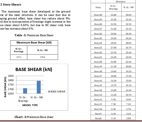
3.2 Story Shears
[image:4.595.36.286.82.334.2]The maximum base shear developed at the ground level of the steel structure. It can be seen that due to sloping ground effect, base shear has reduce about 9%. And due to incorporation of bracings slight increase in the base shear about 0.53%, but due to RC shear wall, base shear has increase about 5%.
Table -3: Maximum Base Shear
Maximum Base Shear (kN)
Sl. Gr.-
Bracings Sl. Gr.- SW
1711 1794
Chart -3
:
Maximum Base shear3.3 Story displacements
[image:4.595.44.533.361.782.2]
Story displacements are presented in below tables for X and Y direction. Due to sloping ground effect, reduction in the displacements of 33% is found and 43% with the utilization of bracings and shear wall on sloping grounds due to earthquake loads along X direction. A negative sway is observed at the bottom story of the steel structure since moment resisting frame is resting on sloping ground. In the regular frame along Y direction, the displacements has increased from 59.1 mm to 73.9 mm due to the orientation of the built up columns. In Y direction also displacements are reduced to 51.6 mm i.e., about 30% due the effect of sloping ground. Additional 19% reduction in the displacements is found due to addition of bracings and shear walls along the peripheral of the steel moment resisting frame.
Table -4:Story vs. Story Displacements – X direction Story Displacements - X
Direction
Story Bracings Sl. Gr.- Sl. Gr.- SW
Story30 34.00 34.00
Story29 33.30 33.20
Story28 32.50 32.30
Story27 31.60 31.30
Story26 30.60 30.30
Story25 29.50 29.20
Story24 28.30 28.00
Story23 27.00 26.70
Story22 25.70 25.40
Story21 24.30 23.90
Story20 22.80 22.40
Story19 21.20 20.80
Story18 19.60 19.20
Story17 18.00 17.50
Story16 16.30 15.80
Story15 14.70 14.10
Story14 13.00 12.40
Story13 11.20 10.70
Story12 9.50 8.90
Story11 7.90 7.30
Story10 6.20 5.70
Story9 4.60 4.20
Story8 3.10 2.80
0.00 5.00 10.00
1 3 5 7 9 1 1
T
IM
E
P
RIOD
(S
ECOND
S
)
MODE
MODE VS.
FREQUENCY
Regular Frame
Sloping Gr.
Sl. Gr.-Bracings
1650 1700 1750 1800 1850
Sl. Gr.-Bracings
Sl. Gr.- SW
B
A
SE
S
H
EA
R
(k
N
)
MODEL TYPE
BASE SHEAR (kN)
© 2017, IRJET | Impact Factor value: 5.181 | ISO 9001:2008 Certified Journal | Page 460
Story7 1.60 1.60
Story6 0.60 0.70
Story5 0.10 0.20
Story4 -0.10 0.02
Story3 -0.05 -0.01
Story2 -0.03 -0.02
[image:5.595.69.559.76.801.2]Story1 -0.02 -0.01
Table -5:.Story vs. Displacements – Y direction Story Displacements - Y
Direction
Story Sl. Gr.-
Bracings Sl. Gr.- SW
Story30 41.80 41.10
Story29 41.00 40.10
Story28 40.10 39.10
Story27 39.00 38.00
Story26 37.90 36.80
Story25 36.60 35.50
Story24 35.20 34.10
Story23 33.70 32.60
Story22 32.10 31.00
Story21 30.40 29.30
Story20 28.70 27.50
Story19 26.80 25.70
Story18 24.90 23.80
Story17 23.00 21.80
Story16 21.00 19.80
Story15 19.00 17.80
Story14 16.90 15.70
Story13 14.90 13.70
Story12 12.90 11.70
Story11 10.80 9.70
Story10 8.80 7.80
Story9 6.90 6.00
Story8 5.00 4.30
Story7 3.30 2.90
Story6 1.80 1.70
Story5 0.90 0.90
Story4 0.40 0.40
Story3 0.10 0.10
Story2 0.00 -0.03
Story1 -0.03 -0.03
Chart -4:Story vs. Displacements – X direction
Chart -5:Story vs. Displacements – Y direction
3.4 Story drifts
It is observed that, due to the sloping ground effect, there will be no drifts up-to story 4 and also story drifts are found to be less than that of regular frame of about 35% less in case of steel moment resisting frame resting on sloping ground provided with bracings. Increase in story drifts with height is observed in all the case of models but it is less than about 22% compared to regular frame resting on level ground
.
Table -6:Story vs. Story Drifts – X direction Story Drifts X -
Direction Story Bracings Sl. Gr.- Sl. Gr.- SW Story30 0.00024 0.00028 Story29 0.00027 0.00030 Story28 0.00030 0.00032 Story27 0.00033 0.00034 Story26 0.00037 0.00037 Story25 0.00040 0.00040 Story24 0.00042 0.00043 Story23 0.00045 0.00045
-20.00 0.00 20.00 40.00 60.00 80.00 S to ry 3 0 S to ry 2 6 S to ry 2 2 S to ry 1 8 S to ry 1 4 S to ry 1 0 St o ry 6 S to ry 2 DI SP L A C E ME NT ( m m ) STORY
STORY VS. DISPLACEMENTS
X - Dir.
Regular Frame
Sloping Gr.
Sl. Gr.-Bracings
Sl. Gr.- SW
-20.00 0.00 20.00 40.00 60.00 80.00 S to ry 3 0 S to ry 2 6 S to ry 2 2 S to ry 1 8 S to ry 1 4 S to ry 1 0 S to ry 6 S to ry 2 DI SP L A C E ME NT ( m m ) STORY
STORY VS. DISPLACEMENTS
- Y Dir.
Regular Frame
Sloping Gr.
Sl. Gr.-Bracings
[image:5.595.309.558.284.431.2]© 2017, IRJET | Impact Factor value: 5.181 | ISO 9001:2008 Certified Journal | Page 461 Story22 0.00047 0.00048
[image:6.595.91.231.106.371.2]Story21 0.00050 0.00050 Story20 0.00052 0.00052 Story19 0.00053 0.00054 Story18 0.00055 0.00056 Story17 0.00056 0.00057 Story16 0.00056 0.00058 Story15 0.00057 0.00058 Story14 0.00057 0.00058 Story13 0.00057 0.00057 Story12 0.00056 0.00056 Story11 0.00055 0.00053 Story10 0.00054 0.00050 Story9 0.00052 0.00046 Story8 0.00049 0.00042 Story7 0.00045 0.00042 Story6 0.00016 0.00017 Story5 0.00005 0.00007 Story4 0.00001 0.00001 Story3 0.00001 0.00000 Story2 0.00001 0.00000 Story1 0.00001 0.00000 Table -7:Story vs. Drifts – Y direction
Story Drifts Y - Direction Story Bracings Sl. Gr.- Sl. Gr.- SW Story30 0.00027 0.00033 Story29 0.00031 0.00035 Story28 0.00035 0.00038 Story27 0.00039 0.0004 Story26 0.00043 0.00043 Story25 0.00046 0.00047 Story24 0.0005 0.0005 Story23 0.00053 0.00053 Story22 0.00056 0.00056 Story21 0.00059 0.00059 Story20 0.00061 0.00061 Story19 0.00063 0.00064 Story18 0.00065 0.00065 Story17 0.00066 0.00067 Story16 0.00067 0.00068 Story15 0.00068 0.00068 Story14 0.00068 0.00068 Story13 0.00068 0.00068 Story12 0.00068 0.00066 Story11 0.00066 0.00064
Story10 0.00065 0.0006 Story9 0.00062 0.00055 Story8 0.00059 0.00048 Story7 0.0005 0.00039 Story6 0.00031 0.00028 Story5 0.00017 0.00018 Story4 0.00009 0.0001 Story3 0.00004 0.00004 Story2 0.00002 0.00000 Story1 0.00002 0.00002
Story drifts are found higher along Y direction as compared to X direction. Along Y direction story drifts are found to be in the range of 0.00002 to 0.00009 unlike in X direction. At level 9, story drift is found to be 0.00055 for steel frame with shear wall resting on sloping grounds which is less than about 45% compared to steel moment resisting frame resting on level ground, and 37.5% and 12% less than that of steel moment resisting frame resting on sloping ground without and with steel bracings respectively.
Chart -6:Story vs. Drifts – X direction
Chart -7: Story vs. Drifts– Y direction
0.00000 0.00020 0.00040 0.00060 0.00080 0.00100 S to ry 3 0 S to ry 2 6 St o ry 2 2 S to ry 1 8 S to ry 1 4 S to ry 1 0 S to ry 6 S to ry 2 ST OR Y DR IFT S STORY
STORY VS. STORY DRIFTS X -
Dir.
Regular Frame
Sloping Gr.
Sl. Gr.-Bracings
Sl. Gr.- SW
0.00000 0.00050 0.00100 0.00150 S to ry 3 0 St o ry 2 6 S to ry 2 2 St o ry 1 8 S to ry 1 4 S to ry 1 0 S to ry 6 S to ry 2 ST OR Y DR IFT S STORY
STORY VS. STORY DRIFTS Y -
Dir.
Regular Frame
Sloping Gr.
Sl. Gr.-Bracings
© 2017, IRJET | Impact Factor value: 5.181 | ISO 9001:2008 Certified Journal | Page 462
4. CONCLUSIONS
From the modal analysis we can conclude that due to the introduction of shear walls in steel moment resisting frame resting on sloping ground, time period will reduce hence building frequency will increase, this is due to increase in stiffness of building due to shear walls.
Buildings resting on sloping ground will have less story shears compared to regular buildings resting on level ground, due to loss in seismic weight from the curtailment of columns and elimination of floor levels.
Story displacements are found to almost same along X and Y direction for bracings and shear walls steel moment resisting frame, but resistance is more for lateral loads for buildings resisting on sloping ground.
Shear walls have more efficient in reducing the story drifts compare to all other structural systems.
REFERENCES
[1]. B.G. Birajdar., S.S. Nalawade., “Seismic Analysis Of
Buildings Resting On Sloping Ground”, 2004.
[2]. S.M .Nagargoje., K.S. Sable., “Seismic Performance Of
Multi-Storeyed Building On Sloping Ground”.
[3]. G Suresh., Dr.E Arunakanthi., “Seismic Analysis Of
Buildings Resting On Sloping Ground And Considering Bracing System”.
[4]. Dr.R.B. Khadiranaikar., Arif Masala., “Seismic
Performance Of Buildings Resting On Sloping Ground (May- Jun. 2014).
[5]. Md Sadruddin., Prof. Amaresha., “Seismic Evaluation
of Multistoried Buildings on Plain Ground and Curve Slope Ground”.
[6]. Narayan Kalsulkar., Satish Rathod.,“Seismic Analysis