© 2016, IRJET | Impact Factor value: 4.45 | ISO 9001:2008 Certified Journal
| Page 999
Design and Analysis of Conical Curved Agitator for Medium Density
Fiber Processing-Review
Akash Shriram Hiwrale
1, Prof. S. J. Parihar
21
Akash Shriram Hiwrale, PG Student Dhanokar Nagar Fauji Bhavan Akot Road Shegaon
2Professor S. J. Parihar, Head of Dept Mecahnical Engineering, P.L.I.T, MS Buldana, Maharashtra, India
---***---Abstract -
This work gives approach for performing stress
analysis of an agitator of a large mixing vessel used in pulping process plant. The analysis is carried out to estimate stress strain and deflection in agitator body. The agitator is subjected to vibration due to multi-axial forces resulting from bending and torsional loading imposed by the mixing operation. The approach followed in this work involves: (1) Stress analysis of agitator shaft for unit displacement using FE method. (2) Estimation of stress amplitude variation using vibration data obtained. The work also discusses an alternative approach for estimating stress amplitude variation through dynamic stress analysis. Research work gives solution for developing the agitator with curved conical shaped Weldment which is made by using welding techniques standard material plates, Agitator looks conical shaped from side view and circular hub is designed to hold the structure of agitator. Project gives result and validation on the basis of software tool as well as mathematical tool. This proves the strength in designed agitator. Along with agitation process of pulping stirrer is also considered which is mounted on top of the agitator hub.
Literature Review
Over the years many review have been published in the liquid mixing area. Example includes the sideman (1996) and van’t Riet (1979) who published critical review of mass transfer liquid contacting system. General reviews have been published by joshi (1982), Midoux and carpenter (1984) and more recently Nienow (1998) published an excellent review of hydrodynamics of stirred bioreactor.
Agitated vessel comes in many shapes and sizes and this has implication for all facets of mixing. Much of literature work has been done on “StandardVessel” so this standard has to be defined, as deviation will obviously effect the literature conclusion.
Agitation is the process of induce motion of material in a specified way. In the chemical and other processing industries, many operations are dependent to a great extent on effective agitation and mixing of fluids. Generally, agitation refers to forcing a fluid by agitator means to flow in a circulatory or other pattern inside a vessel. Agitation is a means mixing of phase can be accomplished and by which mass and heat transfer can be enhanced between phases or
with external surfaces. In the most general sense, the process of mixing is concern with all combinations of phases of the most frequently occurring ones are:
1. Gases with gases.
2. Gases into liquid: dispersion.
3. Gases with granular solids: floatation, pneumatic, conveying, drying.
4. Liquid into gases:-spraying and atomization.
5. Liquid with liquid:-dissolution, emulsification, dispersion.
6. Liquid with granular solids:-suspension.
7. Pastes with each other and with solids.
8. Solids with solids:-mixing of powder.
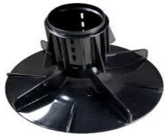
Old Design
Flat casting blades, bottom conical shaped vertical axis rotational.
Weight of agitator = 497 kg
Width reduced from 220 to 150 mm Stress on straight agitator is 11.37 Mpa
[image:1.595.334.503.602.742.2]Deformation on straight agitator is 0.01471 mm but this is at large portion
© 2016, IRJET | Impact Factor value: 4.45 | ISO 9001:2008 Certified Journal
| Page 1000
1. INTRODUCTION
The volume of batch liquid is mixed by an internally mounted mixing device called an agitator impeller. Typically the impeller is a single propeller or turbine blade connected to a shaft that is driven by an electric motor at a fixed speed. There are two classes of impeller agitators: axial-flow and radial-flow, and the mixing characteristics are shown in Figure 2. Axial-flow impellers generate currents parallel with the axis of the impeller shaft. Radial-flow impellers generate currents in a tangential or radial direction to the axis of the impeller shaft. Within the two classes of impellers there exist three main types of impeller design. Figure 1 shows the types and variation of common impellers.
The three types are: propeller, turbine, and paddle. The three main types are utilized in about 95 percent of most batch liquid agitation systems. Standard propellers have three blades, but can be two-bladed, four-bladed, or encased by a circular guard. A revolving propeller traces out a helix in the fluid. One full revolution moves the liquid a fixed distance. The ratio of this distance to the propeller diameter is known as the pitch. Propellers are a member of the axial class of impeller agitators. Turbines are six or more blades mounted at the end of the agitator shaft. They are a member of the radial class of impeller agitators. Turbine diameter is typically 30 to 50 percent of the vessel diameter.
Agitation is the process of induce motion of material in a specified way. In the chemical and other processing industries, many operations are dependent to a great extent on effective agitation and mixing of fluids. Generally, agitation refers to forcing a fluid by agitator means to flow in a circulatory or other pattern inside a vessel. Agitation is a means mixing of phase can be accomplished and by which mass and heat transfer can be enhanced between phases or with external surfaces.
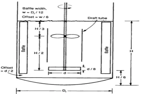
[image:2.595.39.272.573.728.2]1.1 Optimize Mixing By Using The Proper Baffles 1
Fig -2: Stirred tank
A basic stirred tank design, not to scale, showing lower radial impeller and an upper axial impeller housed in a draft tube. Four equally spaced baffles are standard:
Dt = tank diameter,
Dt = Impeller diameter
For radial impeller, 0.3 < d/Dt < 0.6
Why use baffling? During agitation of a low-viscosity liquid, the rotating impeller imparts tangential motion to the liquid. Without baffling, this swirling motion approximates solid-body rotation in which little mixing actually occurs. Think about stirring a cup of coffee or a bowl of soup: The majority of the mixing occurs when the spoon is stopped or the direction of stirring is reversed. The primary purpose of baffling is toconvert swirling motion into a preferred flow
pattern to accomplish process objectives. The most common flow patterns are axial flow, typically
used for blending and solids suspension, and radial flow, used for dispersion. However, baffling also has some other effects, such as suppressing vortex formation, increasing the power input and improving mechanical stability.
1.2
Causing the Mechanical Problems with
Agitators 2
Mechanical problems with agitators are rarely as simple as steady bearings or larger shafts. Either approach may solve the problem or make it worse; you have identified a couple of advantages and problems for each option, but others are possible. From the information you have provided, I can only guess at possible solutions However, from your description, the problem may be in the rigidity of the mounting. If both agitators are having similar problems, it is likely that the support structure is at least contributing to the problems. To make any recommendation for or against the options you mentioned would require a much more thorough analysis than a simple description of the agitator’s. Detailed dimensions and drawings would be needed to completely evaluate the strength of the agitator impellers and shafts.
© 2016, IRJET | Impact Factor value: 4.45 | ISO 9001:2008 Certified Journal
| Page 1001
2. DESIGN METHODOLOGY 2
1) Knowing the material properties and the loading
conditions, the FEM using ANSYS11 will used to get the optimum design of the geometrical parameters of the S shaped agitator elements and to validate the advantages of the differential agitators to give a high agitation performance.
2) The study will ended up with conclusions to maximize agitator performance and optimize the geometrical parameters to be used for manufacturing the differential agitator.
2.1 Agitator Geometry 1
1) The main parts can be considered to design the agitator.
Following Equation shows the standard relations in
geometry of type and location of impeller, proportions of vessel and number of impeller blades.
Da /Dt = 1/3, W/Da = 1/5, L/Dt = 1/4
Where,
Da - Impeller diameter,
Dt - is tank diameter,
W -impeller blade width and L - Is impeller blade length.
2) Finite element modeling using ANSYS11 has been used to optimize the impeller blade dimension to give the experimental result.
3) Both experimental and theoretical analyses done to maximize performance of the differential agitator by parametric and shape optimization.
4) The FEM using ANSYS11 was used to get the optimum design of the geometrical parameters of the differential agitator elements while the experimental test will be performed to validate the advantages of the differential agitators to give a high agitation performance of pulp in the water as an example.
2.2 Impeller Design 2
1) From the power of motor and speed of impeller, the external force which effect in impeller blade as tip force in the end will be calculated. Blade thicknesses will an obvious mechanical design consideration.
2) The blades must be thick enough to handle fluctuating loads without bending or breaking.
3) The following calculation will taking into account the blade strength.
The minimum Blade thickness can be calculated as follows:
Where,
𝑓𝐿 - Is the location fraction for PBT equal to 0.8,
W - Is the width of the blade [m],
N - Is Number of blades,
𝜎𝑏 - Is the blade allowable stress.
α - Is the blade angle (assumed 450).
The problem will be solved as static problem using finite element method using ANSYS11 with this idealization, modeling will be carried out with SOLIDWORK 2011 and will be exported to ANSYS11, which made this idealization: element type 3D Solid brick (ex. 8 node 45), number of element xxxxx, boundary condition fix all degree of freedom at internal surface of impeller.
Force is (calculated input)...N at the tip of impeller and use structural, linear, Elastic, isotropic material with 8027 kg/m3 density, 197 GPa modulus of elasticity and 0.3 Poisson’s ration, impeller after meshing.
After making sure the impeller will safe for the static analysis, the optimization analysis of impeller will be done using finite element modeling using ANSYS 11 to perform the minimum weight design of impeller blade of differential agitator.
2.3 Main Design Features 3
1) Versatile, reliable, high-efficiency mixing hydraulics and material options.
2) Compact Reliable operation and reduced costs. 3) Reliable, simplified and heavy-duty bearing unit hub
with a variety of different lubrication options.
4) Modular design minimizes the spare part inventory costs.
5) Validation with mathematical and CAE analysis.
2.4 Main Applications 4
1) Mixing in tank.
2) Clean and lightly contaminated liquids/ wooden pulp. 3) Thick and Viscose liquids.
4) Fibrous slurries.
© 2016, IRJET | Impact Factor value: 4.45 | ISO 9001:2008 Certified Journal
| Page 1002
3. CAD Tool
SOLIDWORKS is solid modelling CAD software that runs on Microsoft Windows and has been produced by Dassault Systems SOLIDWORKS Corp., a subsidiary of Dassault Systems, S. A. (Velizy, France) since 1997. SOLIDWORKS is currently used by over 2 million engineers and designers at more than 165,000 companies worldwide. FY2011 revenue for SOLIDWORKS was 483 million dollars. SOLIDWORKS is a solid modeller, and utilizes a parametric feature-based approach to create models and assemblies. The software is written on Para solid-kernel.
Parameters refer to constraints whose values determine the shape or geometry of the model or assembly. Parameters can be either numeric parameters, such as line lengths or circle diameters, or geometric parameters, such as tangent, parallel, concentric, horizontal or vertical, etc. Numeric parameters can be associated with each other through the use of relations, which allow them to capture design intent.
Design intent is how the creator of the part wants it to respond to changes and updates. For example, you would want the hole at the top of a beverage can to stay at the top surface, regardless of the height or size of the can. SOLIDWORKS allows the user to specify that the hole is a feature on the top surface, and will then honour their design intent no matter what height they later assign to the can.
Features refer to the building blocks of the part. They are the shapes and operations that construct the part. Shape-based features typically begin with a 2D or 3D sketch of shapes such as bosses, holes, slots, etc. This shape is then extruded or cut to add or remove material from the part. Operation-based features are not sketch-based, and include features such as fillets, chamfers, shells, applying draft to the faces of a part, etc.
4.
CAE Tool
ANSYS, is an engineering simulation software (computer-aided engineering, or CAE) developer headquartered south of Pittsburgh in the South Pointe business park in Cecil Township, Pennsylvania, United States. One of its most significant products is Ansys CFD, a proprietary computational fluid dynamics (CFD) program.
5. ANSYS Workbench Platform
The ANSYS Workbench platform is the framework unifying our industry-leading suite of advanced engineering simulation technology. An innovative project schematic makes it possible to build even complex multiphysics analyses with drag-and-drop simplicity. With bidirectional parametric CAD connectivity, powerful highly automated
[image:4.595.311.557.172.372.2]meshing, an automated project-level update mechanism, pervasive parameter management and integrated optimization tools, the ANSYS Workbench platform delivers unprecedented productivity, enabling process capture and Simulation-Driven Product Development.
Fig -3: Platform of Analysis Process
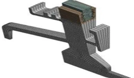
6. ANSYS Meshing
Mesh generation is one of the most critical aspects of engineering simulation. Too many cells may result in long solver runs, and too few may lead to inaccurate results. ANSYS Meshing technology provides a means to balance these requirements and obtain the right mesh for each simulation in the most automated way possible. ANSYS Meshing technology has been built on the strengths of stand-alone, class-leading meshing tools. The strongest aspects of these separate tools have been brought together in a single environment to produce some of the most powerful meshing available.
[image:4.595.322.539.570.697.2]© 2016, IRJET | Impact Factor value: 4.45 | ISO 9001:2008 Certified Journal
| Page 1003
The highly automated meshing environment makes itsimple to generate the following mesh types:
Tetrahedral
Hexahedral
Prismatic inflation layer
Hexahedral inflation layer
Hexahedral core
Body fitted Cartesian
Cut cell Cartesian
Consistent user controls make switching methods very straight forward and multiple methods can be used within the same model. Mesh connectivity is maintained automatically. Different physics requires different meshing approaches. Fluid dynamics simulations require very high-quality meshes in both element shape and smoothness of sizes changes. Structural mechanics simulations need to use the mesh efficiently as run times can be impaired with high element counts. ANSYS Meshing has a physics preference setting ensuring the right mesh for each simulation.
7. CONCLUSIONS
Expected outcomes in conclusion are:
1) My work is in progress then after completion of all work the conical curved agitator presents encouraging results while being compared to other types of agitator.
2) From results it’s found that conical shaped mixing component mounted agitator rotor is feasible to incorporate into vertical feeding, mixing and material transfer devices.
3) Presented structure is validated and concluded as working in safe mode also objective of optimizing engineering manufacturing is possible here replacing casting by weldment body in conical vessel.
4) Also in that we increase the production rate by reducing the cost and weight of agitator.
ACKNOWLEDGEMENT
The author would like to present their sincere gratitude towards the, Prof. S. J. Parihar (Guide) and (Head of the Department of mechanical engineering) for their extreme support to complete this assignment.
REFERENCES
[1] John Frank Pietranski, P.E., Ph.D. "Mechanical Agitator Power Requirements for Liquid Batches” vol.3, 2012.
[2] V. Uhl and J.B Gray, “Mixing Theory” 1967 in Volume 02, In New York 1966,.
[3] McCabe et al. 2001, by „Abraham Rogelio Martin
Garcia‟.“Agitation and Mixing”
[4] André Bakker 1998 Updated: February 15, 2000 by “André Bakker and Julian B. Fasano”.
[5] M. D. Bahr, C. B Weetman in June 1981 researches on,
“Impact Of Side Flow On Mixing Impeller” in chemical engg progress.