http://dx.doi.org/10.4236/wjm.2014.43008
New Materials for Vacuum Chambers
in High Energy Physics
Cédric Garion
Vacuum, Surfaces and Coatings Group, Technology Department, CERN, CH-1211 Geneva 23, Meyrin, Switzerland
Email: [email protected]
Received 12 December 2013; revised 15 January 2014; accepted 14 February 2014
Copyright © 2014 by author and Scientific Research Publishing Inc.
This work is licensed under the Creative Commons Attribution International License (CC BY). http://creativecommons.org/licenses/by/4.0/
Vacuum chambers must fulfil ultra-high vacuum requirements while withstanding thermo-me- chanical loads. This is particularly true in high energy particle accelerator where interactions of particles with matter may induce thermal load, material activation, background… The choice of
the material of the vacuum chamber is crucial for the final application. Metals such as stainless steel, copper and aluminium are usually used. Even with outstanding mechanical and physical properties, beryllium is used for very specific applications because of its cost and toxicity. Ceram-ics such as alumina are usually used for fast magnet vacuum chambers. With the next generation of high energy physics accelerator generation such as CLIC and TLEP, the problematic of high cy-clic thermal load induced by synchrotron radiation is raised. This paper aims at defining some figures of merit of different materials with respect to several load scenarios and presents briefly their vacuum compatibility.
Keywords
Vacuum Chamber; Figure of Merit; Transparency; Radiation Length; Carbon; Beryllium
1. Introduction
always been to offer a cheaper, more readily available alternative to beryllium vacuum chambers for the ex-perimental areas, whilst maintaining equivalent transparency. Several attempts are recorded in the CERN ar-chives, two examples being carbon fibre chambers that were installed in NA48 and LEP. A study has been reini-tiated recently [5].
Nevertheless, this figure of merit is focused on the mechanical aspect and does not take into account thermal and/or thermal fatigue. Indeed, in modern or future high energy physics accelerators, pulsed and/or high energy deposition induced by synchrotron radiation is expected. This heat may lead to high temperature rise and also to high thermal stresses. In this paper, new figures of merits are derived from both mechanical and thermal aspects, considering heat deposition induced by particle interactions with matter.
2. Figure of Merit of Material for Vacuum Chambers
To identify the figures of merit from thermal and mechanical points of view of materials to be applied to UHV thin walled vacuum chambers, the local heat transfer equation and the 1-D constitutive law are used and read, respectively:
T
C T p
t
ρ
∂ = ∆ +λ
∂ (1)
(
)
(
0)
E T T
σ = ε α− − (2)
The thermal behaviour is described by the heat transfer equation (Equation (1)) where p represents the power of heat dissipation, ρ stands for the specific mass. C and λ denote the specific heat capacity and the thermal con- ductivity, respectively. The heat dissipation may have several origins: electrical, mechanical, physical or chemi-cal for examples. For high energy physic applications, it’s assumed that the heat dissipation is driven by the heat deposition induced by the interaction of particles with matter.
The passage and interaction of particles through the matter is generally complex and requires dedicated Monte Carlo tools. In this paper, only general figures are looked for. High-energy electrons predominantly lose energy in matter by bremsstrahlung and high-energy photons by e + e − pair production. The characteristic amount of matter traversed for these related interactions is called the radiation length X0. It is both the mean distance over
which a high-energy electron loses all but 1/e of its energy by bremsstrahlung and 7/9 of the mean free path for pair production by a high-energy photon
X0 is a material parameter that is approximated by [6]:
[ ]
(
)
0 1 716.4 cm ~ 287 1 ln A X Z Z Zρ +
(3)
with Z and A the atomic number and the atomic weight, respectively.
For electrons, the energy deposition induced by bremsstrahlung, is given by:
0
d d
E E
x = −X (4)
For photons, the energy absorption is complex and strongly depends on the photon energy. Three main phe-nomena dominate successively: photoelectric effect, Compton scattering and pair production (Figure 1) [7].
The energy absorption length, λen, defined in [8], is obtained from the mass energy absorption coefficient given in [9] (Figure 2).
In the range 0.1 - 1 MeV, the Compton scattering process dominates the interaction cross section for most of the materials [10]. A power law correlation is used to approximate the energy absorption length with respect to the radiation length. A good approximation is obtained for 0.5
0
~ en X
λ , that is coherent with the linear depend-ence of the Compton cross section with the atomic number [8].
At higher energy, the pair production dominates. Its cross section varies as Z2 [8]. A good linear correlation between the energy absorption length and the radiation length, λen~X0, is obtained, as expected.
Figure 1. Photon cross section of carbon.
Figure 2. Energy absorption length of few material for photons.
Two thermal regimes are considered: a transitory regime for fast phenomenon where diffusion can be ne- glected and a steady state. They both induce temperature rise and therefore thermal stresses. For the first one, the temperature rise is proportional to:
0
1 T
X C
δ
ρ ∝
⋅ ⋅ (5)
To characterize the material and its ability to withstand the temperature rise, it has been normalized with re-spect to the melting temperature, Tf, and a first figure a merit for the material is expressed by:
0
1
f
The temperature increase (Equation (5)) and the constitutive law (Equation (2)) are used to approximate the thermal stresses that could induce thermal fatigue. This thermal stress could be compared to the endurance stress. Nevertheless they have been normalized to the yield stress, σy, which is a more available parameter. Therefore figure of merit related to transitory thermal stresses is given by:
0 y
E
X C
α ρ⋅ σ ⋅
⋅
⋅ (7)
with E the Young modulus. α denotes the coefficient of thermal expansion. This parameter represents the ability of the material to withstand pulsed high energy deposition.
In the case of a thermal steady state, the normalized temperature rise gives a third figure of merit:
0
1
f
X ⋅ ⋅λ T (8)
The transparency of a vacuum chamber is determined as the ratio thickness over the radiation length, t/X0, and
is therefore optimum for the thinnest chamber with the highest radiation length material. From the mechanical point of view, the failure mode of a thin walled vacuum chamber is usually the buckling. The critical buckling pressure is in the form:
3 4 cr E t P R =
(9) where t and R denote the thickness and radius, respectively. A figure of merit for the material, considering the transparency and the buckling strength, can therefore be expressed by:
1 3 0
X E (10)
These four figures of merit are independent even if the Equations (6) and (7) are linked because of the same transient thermal aspect.
3. Material Comparison
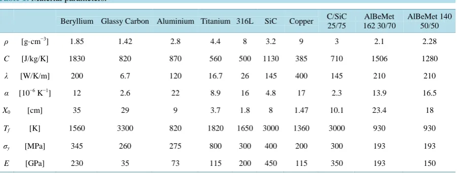
A few materials have been considered and compared to beryllium, usually used or proposed for these applica-tions. Non-linear effects are not taken into account and the material parameters have been defined at room tem-perature (Table 1).
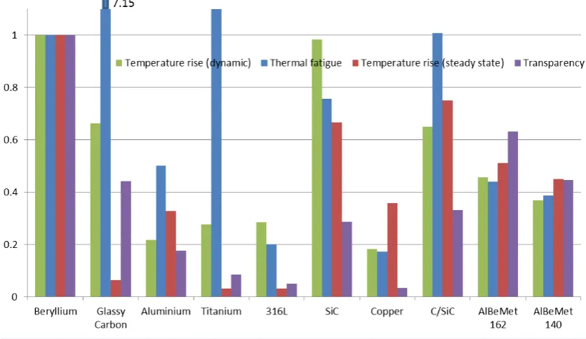
The ratio with respect to the beryllium of the figure of merits considering the different criteria have been evaluated (higher than 1 meaning better than beryllium) and presented in Figure 3.
[image:4.595.89.540.548.720.2]Glassy carbon and silicon carbide (reinforced with carbon fibres or not) are two interesting candidates for “transparent” vacuum chambers. They are good intermediate solutions between beryllium and classical metallic material. Glassy carbon material exhibitsadvantageous thermal fatigue properties, due to its low thermal expan-
Table 1. Material parameters.
Beryllium Glassy Carbon Aluminium Titanium 316L SiC Copper C/SiC 25/75
AlBeMet 162 30/70
AlBeMet 140 50/50
ρ [g·cm−3] 1.85 1.42 2.8 4.4 8 3.2 9 3 2.1 2.28
C [J/kg/K] 1830 820 870 560 500 1130 385 710 1506 1280
λ [W/K/m] 200 6.7 120 16.7 26 145 400 145 210 210
α [10−6 K−1] 12 2.6 22 8.9 16 4.8 17 2.3 13.9 16.5
X0 [cm] 35 29 9 3.7 1.8 8 1.47 10.1 23.4 18
Tf [K] 1560 3300 820 1820 1650 3000 1360 3000 930 930
σy [MPa] 345 260 275 800 300 400 200 300 193 193
sion coefficient and low Young modulus.
A similar figure is obtained in the case of lower energy photon interactions (Figure 4).
4. Alternative Materials to Beryllium
[image:5.595.110.522.194.439.2]Beryllium is an outstanding material with high and homogeneous thermo-mechanical properties (Figures 3 and 4). Nevertheless, it has some drawbacks such toxicity, brittleness, availability and cost. In addition, it is not neces-sarily the best choice for thermal fatigue. Therefore, alternative materials, with comparable properties, are
Figure 3.Comparison of materials according to different figures of merit at high energy photons and electrons.
[image:5.595.104.522.470.712.2]looked for. A study for an application in high energy physics detectors, that requires an optimisation for the transparency, has been initiated [5]. This kind of material, with low atomic number, might be used in a wider scope and not only in experimental areas. Different material technologies are considered:
1) Raw bulk material: the material is homogeneous and leak tight.
2) Material composite: The material is composed of a matrix reinforced with fibres or particulates. The leak tightness is obtained either in the bulk or with a coating. Mechanical properties that can be obtained by homog-enization theories are given by the composite properties.
3) Structural composite: A thin membrane, likely in aluminium, is used to obtain the leak tightness. It is rein-forced to withstand the mechanical loads. The macroscopic behaviour is given by the reinforcement and the aluminium foil.
After beryllium, carbon is the element with the lowest atomic number that is appropriate for this application; therefore all high carbon content materials, especially composites based on carbon fibre that offer high stiffness and high radiation length, are good candidates for transparent vacuum chambers. An overview of the materials that have been considered is presented briefly. It aims at giving main properties and limitations.
5. Raw Material
Glassy carbon (GC) is obtained by the pyrolysis at high temperature of a highly reticulated resin. The material is composed of around 98% (weight) of carbon and 2% of oxygen. The thermal outgassing and the permeation have been measured. The GC grade, manufactured at high temperature (~3000˚C) and provided by HTW, Ger-many, shows a good vacuum performance. The unbaked glassy carbon has a thermal outgassing of around 2.10−9 mbar·l·s−1·cm−2 after 10 hours with a decrease in t−1.4 (Figure 5), whereas the baked sample has a thermal outgassing of around 2.5·10−13 mbar·l·s−1·cm−2 for hydrogen after a baking at 150˚C for 2 hours. The main issue of this material lies in its brittleness and the difficulty to join a glassy carbon part with a standard metallic inter-face flange.
The aluminium well remains a good backup solution since their manufacturing processes and characteristics are known and/or manageable. Thin walled vacuum chambers can be manufactured in aluminium. New grades with lithium are now available (series 2000) or in development (series 5000). The addition of lithium tends to increase the Young modulus the mechanical strength and the transparency. Mechanical and welding tests are on-going to qualify the available grades.
The solution of silicon carbide ceramic has not yet been extensively studied. Preliminary thermal outgassing tests have been carried out on an unbaked sample and a value around 2.10−9 mbar·l·s−1·cm−2 after 10 hours, has been obtained (Figure 5). This material is available in the industry and can be soldered to metallic parts. More detailed study on vacuum performance and feasibility is required.
6. Composite Material
Sample pieces of carbon fibre reinforced resin of 100 × 100 × 2 mm were coated by PVD. Coatings of Alumin-ium, Silicone and Titanium were applied. Coating thicknesses ranged from 100 to 500 nm. When carrying out leak tests on these samples, all items started with a background between 10−9 and 10−10 mbar·l·s−1 and rose to between 10−7 and 10−8 mbar·l·s−1 after several hours [11]. A non-coated sample exhibited similar behaviour. Samples have also been coated by another method (Hipims) and showed similar results. First impressions are that single layer coatings, no matter how controlled the environment, may always have small leaks. This would be coherent with previous studies of coatings on polymers [12] that exhibited pin holes due to the presence of dust. These pin holes led to high thermal outgassing. Further developments are foreseen. The first one is a mul-tilayer coating with intermediate treatments. They would aim at a redistribution of the dust and therefore of the pin holes between two layers. The second alternative is an electrolytic coating with ionic liquid.
Figure 5. Thermal outgassing of unbaked glassy carbon and C/SiC composite materials.
posed. It could be obtained by powder technology and could ease the manufacturing process. Reliability under thermal cycles (bake out) has not been assessed.
A carbon fibre in ceramic matrix composite is an interesting material (Figures 3 and 4). A sample of short carbon fibre reinforced silicon carbide composite has been provided by CeSIC, Germany. This unbaked material, as received, has a thermal outgassing of 4.10−7 mbar·l s−1·cm−2 after 10 hours of pumping and a decrease with time in t−0.34 (Figure 5).
7. Structural Composite
A first solution is based on a thin metallic envelop, reinforced internally to withstand the atmospheric pressure. The internal reinforcement has to exhibit low outgassing and a proposal in C/C (Carbon Fibre Reinforced Car-bon) has been studied. Outgassing tests were made with a Ti external barrier, having obtained a rate of about 1.10−12 mbar·l·s−1·cm−2 after a bake-out at 250˚C [13], which is compatible with previous tests [14] [15]. NEG coating was successfully made and results are promising. After activating for 6 hours at 250˚C the sample that has a coated surface of around 2500 cm2, a pumping speed of 500 l·s−1 for H2 was measured. Nevertheless, the differential thermal expansions between the aluminium envelop and the C/C reinforcement lead to a large de-formation of the thin metallic membrane and therefore limits the reliability of such solution for applications re-quiring a bake out or thermal cycles [15].
Another solution is the external reinforcement of an internal leak tight membrane in aluminium. The rein-forcement might be wrapped carbon fibres with resin or a sandwich structure. Due to the permeability of the re-inforcement, the interface between the membrane and the resin has to withstand the vacuum force most impor-tantly including the bake out when higher stresses are generated due to differential thermal expansion. For polymeric resin, no strong covalent bounds occur and creep, especially at high temperature may result. The strength of the interface between the internal membrane and the reinforcement is a limiting factor.
8. Conclusion
to high energy deposition or that interact with physics particles. They are based on both mechanical and thermal considerations. The figures of merit have to be chosen according to the final applications and requirements. They have been compared for a few materials to beryllium. Glassy carbon shows interesting properties as well as carbon fibre reinforced silicon carbide. Their thermal outgassing has been evaluated for unbaked sample. One grade of glassy carbon exhibits low outgassing and seems to be fully compatible for UHV applications. This work is still on-going and more detailed measurements are in preparation, especially for baked material.
References
[1] Hauviller, C. and Wilson, I. (1974) What Materials Should We Use to Make the Vacuum Chambers in the ISR Ex- pe-rimental Intersections. CERN-ISR-GE/74-52, 1974
[2] Hauviller, C. (1988) Development of Composite Tubes for Experimental Vacuum Chambers of Colliders. Proceedings
of 1st European Particle Accelator Conference, Rome, 7-11 June 1988, 1143-1145
[3] Grobner, O. and Hauviller, C. (1990) LEP Vacuum Chambers for Experimental Regions: Experience with the First Generation, Prospects for the Second Generation. Proceedings of 2nd European ParticleAccelerator Conference, Nice, 12-16 June 1990, 1326-1328.
[4] Engelmann, G., Genet, M. and Wahl, W. (1987) Vacuum Chambers in Composite Material. Journal of Vacuum Sci-
ence & Technology A, 5, 2337. http://dx.doi.org/10.1116/1.574447
[5] Garion, C., Pinto, P.C., Gallilee, M. and Perez, E.J. (2013) Development of Vacuum Chambers in Low Z Material.
Proceedings of the 4th International Particle Accelerator Conference, Shanghai, 12-17 May 2013, THPFI057.
[6] Eidelman, S., et al. (2004) Review of Particle Physics. Physics Letters B, 592, 1. [7] Nakamura, K., et al. (2010)(PDG), JP G 37, 07502.
[8] Hubell, J.H. (1969) Photon Cross Sections, Attenuation Coefficients and Energy Absorption Coefficients from 10 kEv to 100 GeV. NSRDS-NBS 29.
[9] http://www.nist.gov/pml/data/xraycoef/index.cfm
[10] Tavernier, S. (2010) Experimental Techniques in Nuclear and Particle Physics. Springer, Berlin Heidelberg.
http://dx.doi.org/10.1007/978-3-642-00829-0
[11] Charaux, A. (2012) Etude de la faisabilité d’une chambre à vide en matériaux composites, CERN EDMS 1240624, 2012
[12] Payan, S. (2001) Comportement à la Corrosion Galvanique de Matériaux Composites à Matrice d’alliage d’Aluminium Renforcée par des Fibres de Carbone Haut-Module. PhD Thesis, Université Bordeaux I, Talence.
[13] Schneider, G. (2011) Private Communication.