International Journal of Emerging Technology and Advanced Engineering
Website: www.ijetae.c om (ISSN 2250-2459, ISO 9001:2008 Certified Journal, Volume 4, Issue 9, September 2014)
481
Experimental Study on the Performance of Cross Flow
Regenerator in Liquid Desiccant Cooling System
Archit Kumar Vias
1, Rakesh Thakur
21,2Research Scholar, Punjab Technical University, Kapurthala, Punjab, India.
Abstract- The regenerator is one of the important components used in liquid desiccant cooling system. It is the reverse of dehumidifier. Desiccant gets diluted in dehumidifier, where as its concentration is increased in regenerator. In experimental set up, the regenerator is packed with PVC packing and TEG is used as a liquid desiccant. Heat is supplied in the form of hot air to increase the concentration of desiccant. The effect of various parameters like mass flow rate of air, inlet air temperature for different inlet desiccant temperatures is studied upon outlet parameters like evaporation rate, desiccant outlet temperature and change in concentration and the results are shown in the form of graphs.
Keywords-TEG, regenerator, desiccant and PVC packing. I. INT RODUCT ION
Desiccant cooling technology is an emerging technology in the field of air conditioning system which controls humidity levels for conditioned air spaces to great extent. Desiccant is a material which has strong affinity for moisture. These materials absorb moisture due to difference in vapor pressure. Desiccants are of two types namely solid desiccant and liquid desiccant. Some of the solid desiccants are silica gel, calcium chloride. A liquid desiccant is a hygroscopic liquid used to remove water. Some liquid desiccants are glycols (diethylene, tri ethylene, tetra ethylene). The liquid desiccants can be regenerated. Regeneration means that the water absorbed by these substances can be separated from them and again they are used for dehumidification of air. The selection of the desiccant depends on their ability to hold large quantities of water, their ability to be reactivated and cost. Desiccant system works in conjunction with conventional air conditioning system to dehumidify the air. Liquid desiccant has several advantages over solid desiccant. The pressure drop through the liquid desiccant is lower than that through a solid desiccant system and can be stored for regeneration by some inexpensive energy. As the desiccant vapor pressure increases due to the presence of moisture that it has attracted, the desiccant material is transferred to a reactivation/regeneration process. In regeneration process, hot air passed over the desiccant. The vapor pressure of hot air is lower than the desiccant surface and this difference in vapor pressure forces the moisture to transfer from the desiccant surface into hot air stream.
After the regeneration process, the desiccant is again used for dehumidification process.
A. Types of Desiccant
There are two types of desiccants namely solid desiccant and liquid desiccant. A solid, such as silica gel or calcium chloride [CaCl2], used in a gas-dehydration unit to remove water and moisture. The desiccants are placed as beds through which wet gas is passed. The main limitation of the use of solid desiccants is that they abs orb only limited quantities of water. When the desiccant saturation point is reached, the solid desiccant must be replaced. Another limitation is that sometimes water cannot be removed from it. Some of the solid desiccants are dehydrate, dry gas, dry-bed dehydrator, wet gas. A hygroscopic liquid used to remove water and water vapor from a gas stream. Some liquid desiccants are glycols (diethylene, triethylene and tetra ethylene), which are substances that can be regenerated. Regeneration means that the water absorbed by these substances can be separated from them. Some liquid desiccants, such as methanol or ethylene, cannot be regenerated. Some of the liquid desiccants are as methanol or ethylene. Liquid desiccant have several advantages over solid desiccant. The pressure drop through th e liquid desiccant is lower than that through a solid desiccant system and can be stored for regeneration by some inexpensive energy such as solar energy and waste heat.
B. Types of desiccant cooling system
Different types of desiccant cooling systems are Solid desiccant system, liquid desiccant system hybrid desiccant system and Solar based desiccant systems.
1.) Solid Desiccant System: Solid desiccant system is that system which uses solid desiccant. Solid desiccant system is generally used for industrial applications. The configurations or technologies of solid desiccant system are:
International Journal of Emerging Technology and Advanced Engineering
Website: www.ijetae.c om (ISSN 2250-2459, ISO 9001:2008 Certified Journal, Volume 4, Issue 9, September 2014)
482
2.) Liquid Desiccant System: Liquid desiccant system is that system which uses liquid desiccant. In liquid desiccant system, there are two chambers; one to perform the dehumidification process and other to perform the regeneration process. The processed air from the dehumidification chamber enters into the conditioned space.
The working operation of liquid desiccant system is simple. In the dehumidification process, the strong desiccant solution that has been brought into contact with the air absorbs the moisture from the air and gets diluted. After that, the desiccants must be regenerated to a useful level of concentration. Desiccant solutions can be regenerated below temperatures of 800C for which hot air blower is utilized. Both air and concentrated desiccant enter the dehumidifier at low temperature, and the water vapor content is transferred from the air to the desiccant. In the regenerator, the air temperature is low and the diluted desiccant is heated to a high temperature by hot air blower. The air and the desiccant enter into the regenerator and water vapor is transferred from the desiccant solution to the air.
3.) Hybrid Desiccant System: a hybrid system, the desiccant dehumidifier handles the latent cooling load and VCS/VAS handles the sensible cooling load. In contrast, a hybrid solid desiccant system has to first dehumidify the air in a desiccant wheel and then cool it in a cooling coil. In both the cases the required chemical dehumidification would be less than the stand alone DCS, as no further moisture needs to be added (in an evaporative cooler) to achieve cooling. Further, as the cooling coil is maintained at higher apparatus dew point (ADP) than a standalone VCS, the overall COP is also high. Waste heat from condenser may also be used for regeneration (part or full) of desiccant. So considerable energy savings can be achieved by using these systems instead of conventional systems using refrigerated coils alone, especially for high latent load and low humidity applications.
4.) Solar based Desiccant Cooling System: According to this principle, author established a compound solar liquid desiccant air-conditioning system (CSLDAS), and through the numerical simulation, analyzed the performance and operation energy consumption. Results indicate that CSLDAS is more economical and energy-saving.
In the dehumidification process, use of natural cold source to cooling and dehumidify fresh air, reduce dehumidifier air inlet humidity ratio and temperature, pretreated fresh air direct contact with desiccant within dehumidifier, the air moisture will be further absorbed by desiccant, the air is dried, and achieved to the supply air status, later, feed into the air-conditioning room, to removal indoor latent cooling load. In this process, air humidity ratio and desiccant concentration will be down respectively
II. LIT ERAT URE REVIEW
Abdul Wahab et al. [2] discussed the performance of air dehumidifier using triethylene glycol (TEG) as a desiccant. Three differently structured packing densities were used (77, 100 and 200 m2/ m3). The performance of the dehumidifier was evaluated and expressed in terms of the moisture removal rate and the dehumidifier effectiveness. The experimental work was undertaken to study the effects of several influencing design factors on this performance. The design factors covered included the air and TEG flow rates, air and TEG inlet temperatures, inlet air humidity and the inlet TEG concentration. The desiccant flow rate investigated was much less than that covered in previous studies and the range of the inlet temperatures of air and desiccant was significantly wider. The objective of this study was to use the multiple regression method and the principal component analysis to obtain statistical prediction models for the water condensation rate and the dehumidification effectiveness in terms of these desig n factors.
International Journal of Emerging Technology and Advanced Engineering
Website: www.ijetae.c om (ISSN 2250-2459, ISO 9001:2008 Certified Journal, Volume 4, Issue 9, September 2014)
483
V. O Berg et al. [28] discussed the experimental investigation of the heat and mass transfer between a liquid desiccant (triethylene glycol) and air in a packed bed absorption tower using high liquid flow rates. A high performance packing that combines good heat and mass transfer characteristics with low pressure drop is used. The rate of dehumidification, as well as the effectiveness of the dehumidification process is assessed based on the variables listed above. Good agreement is shown to exist between the experimental findings and predictions from finite difference modeling. In addition, a comparison between the findings in the present study and findings previously reported in the literature is made. The results obtained from this study make it possible to characterize the important variables which impact the system design.C. K. Chau et al. [3] discussed the sorption characteristics of water and toluene vapors in various concentrations of triethylene glycol (TEG) solution flowing through a packed-bed dehumidifier are investigated in this paper. A multi-component model was constructed using the reported equilibrium relationships of toluene and water vapors in TEG solutions together with the Krishna-Standart multi-component mass transfer correlation. The effects of liquid-to-air ratios, TEG inlet temperatures, air inlet temperatures were reported on the moisture and toluene removal rate as well as the moisture and toluene removal efficiency of the packed dehumidifier. Running the packed dehumidifier in a higher liquid-to-gas flow ratio generally increased the removal rates and efficiencies of both water vapor and toluene vapor from the airstream. Increasing inlet temperatures of the TEG solution led to a decrease in the removal rate of water vapor when running the packed dehumidifier at a high liquid-to-gas flow ratio. However, there was no significant change in the toluene vapor removal rate or toluene removal efficiency when the flow rate of the inlet TEG solution was increased.
Esam Elsarrag et al. [26] discussed structured packing which represents the newest development in high efficiency, high capacity packing for heat and mass transfer in contrast to the traditional, randomly placed packing material. The main objectives of this study are to develop design guidelines and to assess the performance of a structured packed liquid desiccant-evaporative cooling system in the modified comfort zone. Theoretical and experimental studies of the simultaneous heat and mass transfer between air and desiccant in a packed absorption tower are conducted. Triethylene glycol (TEG) is used as a desiccant and cellulose rigid media pads are u sed as structured packing.
The packing arrangements have provided minimum carryover of TEG and produced low pressure drop. Through the study of the absorber, important design variables are defined. It is found that high liquid flow rates do not have a significant effect on the system performance if the liquid to airflow ratio exceeds the value of 2. The theoretical model is compared with the experimental results. The effect of dehumidification on evaporative cooling performance is carried out. A reduction of 4.5°C to 9°C in the wet-bulb temperature was obtained from the dehumidifier. Design guidelines have been written to help in designing such systems.
III. EXPERIMENT AL SET UP AND PROCEDURE
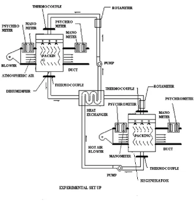
The experimental set up consists of two rectangular packed towers, one for dehumidifier and other for regenerator. The two rectangular towers of size (1 foot x 1 foot x 2 feet) are made of sheet metal in sheet metal shop. After that towers are packed with PVC frill of size (1 foot x 1 foot x 1 foot), which is a packing material. Two rectangular ducts of size 1 foot and 5 inches x 5 inches in cross-section are attached on both sides of the dehumidifier (one for inlet & one for outlet) and regenerator. The top of the dehumidifier and regenerator is provided with a plate having a large number of holes and act as sprayer. A heat exchanger is made of sheet metal and covered with thick sheet of thermo Cole to avoid the heat loss.
Heat exchanger is used to exchange the heat between desiccant after passing through dehumidifier & after passing through the regenerator.
Our experimental set up consists of an arrangement of cross flow between desiccant and air. The desiccant flows vertically whereas air flows horizontally. The regenerator is provided with hot air blower for the regeneration process i.e. heating element is attached with blower. The pump is used to lift the desiccant from regenerator to heat exchanger. Last step in the completion of set up involves the attachments of the instruments such as manometer, thermocouple and psychrometer to measure the various parameters at inlet and outlet.
International Journal of Emerging Technology and Advanced Engineering
Website: www.ijetae.c om (ISSN 2250-2459, ISO 9001:2008 Certified Journal, Volume 4, Issue 9, September 2014)
484
After this the inlet desiccant temperature is changed to new value and kept constant to study the effect on outlet parameters.Similarly the inlet air temperature was changed with the help of heating element and its effect was studied on various outlet parameters for different inlet desiccant temperatures.
[image:4.612.77.460.202.603.2]International Journal of Emerging Technology and Advanced Engineering
Website: www.ijetae.c om (ISSN 2250-2459, ISO 9001:2008 Certified Journal, Volume 4, Issue 9, September 2014)
485
Figure 2 shows the actual diagram of the e xpe rime ntal se t up
IV. RESULT S AND DISCUSSION S
The performance of regenerator was investigated by performing a number of experiments. The effect of mass flow rate of air and mass flow rate of solution on different outlet parameters like change in concentration, outlet desiccant temperature, evaporation rate, outlet dbt of air and change in specific humidity were studied. The results were gathered and plotted graphically.
A. Effect of mass flow rate of air on outlet parameters. The effect of mass flow rate of air was studied on various outlet parameters like change in concentration, outlet solution temperature, evaporation rate, outlet dbt of air and change in specific humidity for different values of inlet solution temperature. The mass flow rate was varied from 0.95 x 10⁻² kg/s to 1.25 x 10⁻² kg/s. Here the other parameters like inlet air temperature and mass flow rate of solution were kept constant. Inlet air temperature was 22°C & mass flow rate of the solution was 0.02 kg/s.
[image:5.612.316.559.141.333.2]In the first set of experiments, the effect of mass flow rate of air was studied on concentration of the solution for different values of inlet solution temperature. In this experiment, it was found that change in concentration increases with mass flow rate. This is due to the fact that more air interacts with the solution with increase in mass flow rate and leads to the increase in concentration change. Figure III shows the variation of change in concentration with mass flow rate.
Figure 3 shows the e ffe ct of mass flow rate of air on change in conce ntration at diffe re nt inle t solution te m p.
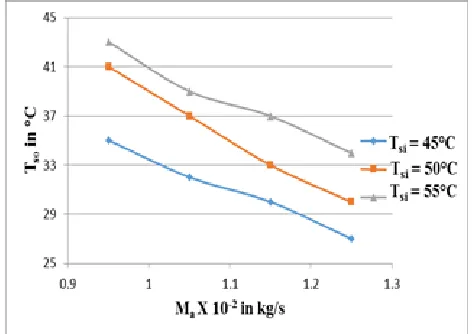
Secondly, the variation of solution outlet temperature was studied with mass flow rate of air at different inlet solution temperature. It was found that solution outlet temperature decreased with mass flow rate of air. It happened due to the reason that more air interacts with solution which leads to more evaporation and outlet solution temperature decreases .
Figure 4 shows the effect of mass flow rate of air on Desiccant outle t te mpe rature at diffe re nt inle t solution te mp.
0.4 0.5 0.6 0.7 0.8 0.9 1 1.1 1.2 1.3
0.9 1 1.1 1.2 1.3
Δ
X
i
n
%a
g
e
M
ax 10
-2in kg/s
T
si=45 C
T
si=50 C
[image:5.612.55.273.142.294.2] [image:5.612.325.562.458.625.2]International Journal of Emerging Technology and Advanced Engineering
Website: www.ijetae.c om (ISSN 2250-2459, ISO 9001:2008 Certified Journal, Volume 4, Issue 9, September 2014)
486
Thirdly, the variation of evaporation rate was studied with mass flow rate of air at different inlet solution temperatures. The investigation revealed that evaporation rate increases with mass flow rate of air. Also the experiment shows that stronger desiccant solution was available at higher desiccant’s temperatures for the same air flow rate.The increase of moisture removal rate is due to the better contact between the air and the liquid desiccant which increases the mass transfer coefficient between the air and desiccant.0 0.005 0.01 0.015 0.02 0.025
0.9 1.1 1.3
M
ev
a
p
in
k
g
/s
M
ax 10
-2in kg/s
T
si=45 C
T
si=50 C
[image:6.612.325.562.138.324.2]T
si=55 C
Figure 5 shows the effect of mass flow rate of air on evaporation rate at diffe re nt inle t solution te mp.
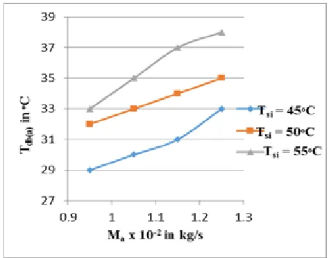
Fourthly, the variation of outlet dbt of air was studied with mass flow rate of air at different inlet solution temperatures and it was found that it also increases with mass flow rate of air. This is due to the fact that air absorbs moisture from the solution and this increases the outlet dbt of air. The specific humidity of air also increases at the outlet due to moisture contents.
Figure 6 shows the effect of mass flow rate of air on outlet dbt of air at diffe re nt inle t solution te mp.
[image:6.612.53.283.261.436.2]At last, the variation of change in specific humidity of air was studied with mass flow rate of air at different inlet solution temperatures . The humidity at outlet was greater than the humidity at inlet leads to increase in change in concentration. The change in concentration would be higher at higher desiccant temperatures.
[image:6.612.326.562.435.592.2]International Journal of Emerging Technology and Advanced Engineering
Website: www.ijetae.c om (ISSN 2250-2459, ISO 9001:2008 Certified Journal, Volume 4, Issue 9, September 2014)
487
B. Effect of mass flow rate of solution on outlet parameters for constant mass flow rate of air.
The effect of mass flow rate of solution was studied on various outlet parameters like change in concent ration, outlet desiccant temperature, evaporation rate, outlet dbt of air and change in specific humidity for different values of inlet solution temperature and following graphs were plotted. Mass flow rate of the air was 0.95 x 10⁻² kg/s and the air inlet temperature was 22°C.
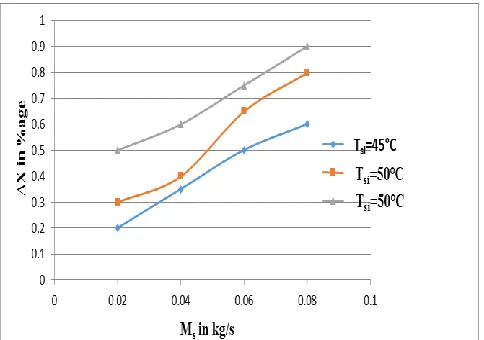
[image:7.612.320.571.238.415.2]Firstly, the variation of change in concentration was studied with mass flow rate of solution. The flow rate of solution was varied from 0.02 kg/s to 0.08 kg/s to study the effect. It was found that change in concentration increases with mass flow rate of solution. This is due to the fact as mass flow rate of solution increases, more solution comes in contact with the same amount of air for particular value of Tai and it will increases the heat and mass transfer. When contact was increased, more water vapor would be released and concentration at outlet increased. Figure 8 shows the variation of change in concentration with mass flow rate of solution for different solution temp.
Figure 8 shows the effect of mass flow rate of solution on change in conce ntration at diffe re nt inle t solution te mp.
Next graphs show the variation of mass flow rate of solution on evaporation rate, outlet dbt of air and change in specific humidity at different inlet air temperatures. Experimentally it was found that evaporation rate increases with mass flow rate of solution. This is due to the fact that When the desiccant flow rate was increased, there would be a good wetting area, and hence a good contact area between air and desiccant which will increase the heat and mass transfer.
[image:7.612.48.290.384.554.2]When the contact was increase, more water vapor would be released and thus increasing the evaporation rate and humidity at outlet. So change in humidity also increases and corresponding dbt of the air also increases. Figure 9 shows the variation of evaporation rate with mass flow rate of solution & figure 10 shows the variation of outlet dbt of air with mass flow rate of solution.
Figure 9 shows the effect of mass flow rate of solution on evaporation rate at diffe re nt inle t soluti on te mp.
Figure 10 shows the e ffect of mass flow rate of solution on outle t dbt of air at diffe re nt inle t solution te mp.
0 0.002 0.004 0.006 0.008 0.01 0.012 0.014 0.016 0.018 0.02
0 0.05 0.1
M
e
v
a
p
in
k
g/
s
M
sin kg/s
T
si=45 C
T
si=50 C
[image:7.612.323.572.452.640.2]International Journal of Emerging Technology and Advanced Engineering
Website: www.ijetae.c om (ISSN 2250-2459, ISO 9001:2008 Certified Journal, Volume 4, Issue 9, September 2014)
[image:8.612.52.288.140.284.2]488
Figure 11 shows the e ffect of mass flow rate of solution on change in spe cific humidity at diffe re nt inle t solution te mp.
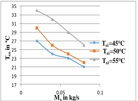
Last graph shows the variation of solution outlet temperature with mass flow rate of solution. It was found that solution outlet temperature decreases with mass flow rate of solution. This is due to the fact that as mass flow rate of solution increases, there would be more wetting area and this will increase more heat and mass transfer. More heat transfer from the solution decreases the outlet temperature of the solution. Figure 12 shows this variation.
Figure 12 shows the e ffect of mass flow rate of solution on outle t solution te mpe rature at diffe re nt inle t solution te mp.
V. CONCLUSION
This paper concluded the effect of inlet parameters like mass flow rate of air and mass flow rate of solution on various outlet parameters like change in concentration, outlet solution temperature, mass evaporation rate, outlet dbt of air & change in specific humidity the result was formulated in the form of graphs as shown above. The aim
of the experiment was to regenerate the desiccant for further dehumidification process.
The change in concentration increases with mass flow rate of air at different inlet solution temperatures. Also the mass evaporation rate, outlet dbt of air & change in specific humidity also increases with mass flow rate of air. But the outlet solution temperature decreases.
The change in concentration increases with mass flow rate of solution at different inlet solution temperatures. Also the mass evaporation rate, outlet dbt of air & change in specific humidity also increases with mass flow rate of air. But the outlet solution temperature decreases. The results are in agreement with other papers.
VI. NOMENCLAT URE
MMass flow rate in (kg/s) T Temperature (°C)
ΔX Change in concentration in (%age)
∆ω Change in specific humidity in (kg/kg of air) TEG Triethylene glycol
a air s solution evap evaporation dbt dry bulb temp. i inlet o outlet
Ack nowledgement
We would like to thank Punjab Technical University, Kapurthala and IET, Ropar to give opportunity to carry out this research work.
BIBLIOGRAPHICAL REFERENCES
[1] S.A. Abdul-Wahab, Y.H. Zurigat, M.K. Abu-Arabi, (2004), “ Air dehumidification by triethylene glycol desiccant in a packed column”, Energy Conversion and Management, pp. 141 –55. [2] Y.H. Zurigat, M.K. Abu-Arabi, S.A. Abdul-Wahab, (2004),
“Predictions of Moisture Removal rate and Dehumidification Effectiveness for Structured Liquid Desiccant Air Dehumidifier”, Energy, pp 19-34.
[3] C.K. Chau and W.M. Worek, (2009), “ Cosorption Processes of T riethylene Glycol in a Packed Bed Liquid, desiccant Dehumidifier,” HVAC &Research, Vol. 15, No. 2, pp 189-210 [4] S. A. Abdalla, Kamal N. Abdalla,(2006),”A Radiant Air-
Conditioning using Solar-Driven Liquid Desiccant Evaporative Water cooling”, Vol. 1, No. 2 (2006) pp 139- 157.
[5] Mei VC, Lavan Z. Performance of cross-cooled desiccant dehumidifiers. T rans ASME J solar energy 1983; 105:300 -304. [6] Nelson DJ, Wood BD. Evaporation rate model for a natural
convection glazed collector/regenerator. Trans ASME J solar energy engng 1990; 112:51-57.
[7] Hajji A,Khalloufi S, Improving the performance of adsorption heat exchanger using finned structure. Int J heat mass transfer 1996; 39(8):1677-1686.
17 19 21 23 25 27 29 31 33 35
0 0.05 0.1
Tso
in
°
C
M
sin kg/s
[image:8.612.49.288.422.597.2]International Journal of Emerging Technology and Advanced Engineering
Website: www.ijetae.c om (ISSN 2250-2459, ISO 9001:2008 Certified Journal, Volume 4, Issue 9, September 2014)
489
[8] Gandhidasan P. A simple analysis of an open regeneration system. Solar energy 1983; 31(3):343-345.
[9] Yang R, Wang PL. Experimental study of a forced convection solar collector/regenerator for open cycle absorption cooling. T rans ASME J solar energy engng 1994; 116:194 -199.
[10] Saito Y. Regeneration characteristics of adsorbent in the integrated desiccant/collector. T rans ASME J solar energy engng 1993; 115:169-175.
[11] Ameel T A, Gee KG. Wood BD. Performance predictions of alternative, low cost absorbents for open cycle absorption solar cooling. Solar energy 1995; 54(2):65-73.
[12] Pesaram AA. Desiccant degradation in desiccant cooling systems. A system study. Trans ASME J solar energy engng 1993; 115:273 -240. [13] Waugaman DG, Kini A, Kettleborough CF. A review of desiccant cooling systems. Journal of energy resource technology 1993; 115(1):1-8.
[14] Kessling W , Laevemann E, Peltzer M. Energy storage in open cycle liquid desiccant cooling systems. International journal of refrigeration 1998; 21(2):150-156.
[15] Fumo N, Goswami DY. Study of an aqueous LiCl desiccant system; air dehumidification and desiccant regeneration. Solar energy 2002; 72(4):351-361.
[16] Ahmed M. Hamed, T M Kaseem, AS Alosaimy, EB Zeidan. Experimental performance of a liquid desiccant rotating wick regenerator under climatic conditions of Taif city. Wulfenia journal, Klagenfurt, Austria 2012; ISSN: 1561-882X: 223-243. [17] Lof GOG, Lenz T G, Rao S. Coefficients of heat and mass transfer in
a packed bed suitable for solar regeneration of aqueous LiCl solutions. Journal of solar energy engineering 1984; 106(4 ):387-392. [18] Patnaik S, Lenz T G, Lof GOG. Performance studies for an experimental solar open cycle liquid desiccant air dehumidification system. Solar energy 1990; 44(3):123 -135.
[19] Gommed K, Grossman G, Ziegler F. Experimental investigarion of a LiCl- water open absorption system for cooling and dehumidification. Journal of solar energy engineering 2004; 126(2):710-715.
[20] Liu XH, Jiang Y, Chang XM, Yi XQ. Experimental investigation of the heat and mass transfer between air and liquid desiccant in a cross flow regenerator. Renewable energy 2007; 32(10):1623 -1636. [21] Yin YG, Zhang XS, Chen ZQ, Experimental study on dehumidifier
and regenerator of liquid desiccant cooling air conditioning system. Building and environment 2007; 42(7):2505 -2511.
[22] Martin, V., Goswami, DY, 1999. Heat and mass transfer in packed bed liquid desiccant regenerators-An experimental investigation. T ransactions of the ASME Journal of solar energy engineering 121,162-170.
[23] Factors. HM, Grossman, G, 1980. A packed bed dehumidifier/regenerator for solar air conditioning with liquid desiccants solar energy 24, 541-550.
[24] GI Sultan, Ahmed M Hamed, AA Sultan, 2002. T he effect of inlet parameters on the performance of packed tower -regenerator. Renewable energy 26,271-283.
[25] Fumo, N, Goswami, DY 2002. Study of an aqueous LiCl desiccant system. Air dehumidification and desiccant regeneration. Solar energy 72 (4), 351-361.
[26] Esam Elsarrag, 2006. Performance study on a structured packed liquid desiccant regenerator. Solar energy 80, 1624-1631 [27] Gandhidsan, P, 2005. Quick performance predictions of liquid
desiccant regeneration in a packed bed. Solar energy 79 (1), 47 -55.[28].