International Journal of Emerging Technology and Advanced Engineering
Website: www.ijetae.com (ISSN 2250-2459, ISO 9001:2008 Certified Journal, Volume 5, Issue 4, April 2015)
16
The Analysis and Simulation of Robot Kinematics and
Dynamics Based on RoboAnalyzer
Qi Fei
1, Ping XueLiang
2, Liu Jie
3, Jiang Yi
41,2,3,4Jiangnan University, Jiangsu Province Key Laboratory of Advanced Food Manufacturing Equipment and Technology, Wuxi 214122
Abstract—Robot kinematics and dynamics is the basis of robotics research, providing the important basis for robot path planning and motion control etc. The paper focuses on the six degrees of freedom industrial robot which is developed independently, adopts the D-H method to do the forward kinematics analysis and inverse kinematics analysis for robot, establishes the kinematics model, and uses Lagrange method for robots’ dynamics analysis, and then builds the relational model among mechanical arms and their force (or torque), at last, the paper uses the simulation software to illustrate the above to prove the correctness and rationality of the models.
Keywords—robot, kinematics, Dynamics, simulation, D-H method
I. INTRODUCTION
With the development of industrial automation, the robot has become the indispensable and cheap labor in the production, and the research of the robot is much hotter. Robot kinematics and dynamics is the basis of robotics research, and robot kinematics is to research the relative relationship between the end pose of robot and robot kinematics parameters, which is the basis of robot control study [1]. The robot dynamics is mainly the study of the correlative relationship between the movement of robot arm movement and its force (or torque) [2]. Analysis of robot kinematics and dynamics is the base of robot technology research and the key to study robot trajectory planning and motion control [3].
The paper analyses the six degrees of freedom industrial robot kinematics which is developed independently, using the D-H method to establish the relation between forward and inverse solution in the robot kinematics model so as to study the robot kinematics, and adopting Lagrange method to build the relation between the movement of robot links and its force (or torque).
Finally, the paper shows the simulation test of robot kinematics and dynamics using RoboAnalyzer simulation software.
II. ROBOT KINEMATIC ANALYSIS
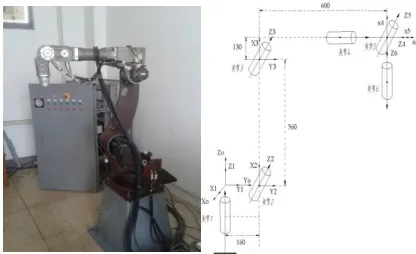
[image:1.612.344.552.438.565.2]The paper focused on the independently developed Six-DOF industrial robot (the link coordinate system is shown in the Fig.1, D-H parameters as shown in the table 1), to analyze the kinematics, and builds the relation between robot end pose and robot parameters through D-H model which is the established kinematics model using the homogeneous coordinate transformation matrix that Denavit and Hartenberg proposed [4]. The robot kinematics includes forward kinematics and inverse kinematics: forward kinematics is to use each known joint angle to solve the robot end pose; the inverse kinematics is to use the known end pose to solve each joint angle value.
International Journal of Emerging Technology and Advanced Engineering
Website: www.ijetae.com (ISSN 2250-2459, ISO 9001:2008 Certified Journal, Volume 5, Issue 4, April 2015)
17
TABLE 1
THE D-H PARAMETERS TABLE OF ROBOT Link
i
i(°)
i-1 (°)a
i-1 (mm)d
i (mm)β
i (°)1 1(90°) 0° 0 0 0
2 2(-90°) -90° 160 0 0
3 3(0°) 0° 560 0 0
4 4(0°) -90° 130 600 0
5 5(90°) 90° 0 0 0
6 6(0°) -90° 0 0 0
A. The analysis of robot forward kinematics
The relation between adjacent links of robot can be shown using the homogeneous coordinate transformation matrix, firstly to establish the coordinate system of each robot joint, and then to get the homogeneous coordinate transformation matrix according to the conversion in the coordinate system, as shown in the formula (1).
1 0 0 0 0 ) , ( ) , ( ) , ( ) , ( 1 1 1 1 1 1 1 1 1 1 1 1 i i i i i i i i i i i i i i i i i i i i i i i c d c s c s s s d s c c c s a s c d Z Trans Z Rot a X Trans X Rot T (1)
Among that: i is the joint code, c is cos, and s is sin. θ, d, α, a are the robot structure parameters, which shows the relationship among the robot links. θ is the included angle between robot joints xi-1 and xi around the z axis, namely
link angle. d is the translational distance of xi-1 and xi along
the z axis, namely the distance between two links. a is the rotation angle of zi-1and zi around x axis, namely the joint
angle. a is the translational distance of zi-1 and zi along the
x axis, namely the distance between two links.
Multiply the transformation matrix among each robot link to get the transformation matrix that robot end coordinate is relative to the base coordinate of robot, as shown in the formula (2).
1 0 0 0 6 5 5 4 4 3 3 2 2 1 1 0 6 0 z z z z y y y y x x x x p a o n p a o n p a o n T T T T T T T (2)
B. The analysis of robot inverse kinematics
The inverse kinematics of the robot is to use the known end pose of robot to solve each joint angle, and the solving methods of the inverse kinematics are various. Among these methods, the most widely used one is Closed Method, because it has the quick calculating speed and high efficiency, and it is easy to real-time control [5]. Closed solution contains two methods: geometric method and algebraic method. Because of three joint shafts of the established robot model intersect at one point, this paper will adopt the algebraic method, which refers to that the inverse transformation matrix of each joint pre-multiplies both ends of equation set, and separates the joint variables, and then solve each joint variable value according to the equal elements of both end of matrix.
First, the homogeneous coordinate transformation matrix of robot end pose can be shown:
) T( ) T( ) T( ) T( ) T( ) T( 1 0 0 0 n n n T 6 5 6 5 4 5 4 3 4 3 2 3 2 1 2 1 0 1 z y x 0
6
z z z y y y x x x p a o p a o p a o (3)
The two ends of equation set pre-multiplies respectively
) ( T-1 1 0
1 、 T(1,2,3)
-1 0
3 、 T(1,2,3,4) -1
0
4 、 T(1,2,3,4,5) -1
0
5 to substitute into the above formula to solve each joint variable value θ1、θ2、θ3、θ4、θ5、θ6,as shown in the
following type. )) p + sqrt(p atan2(0, -) ,p atan2(p 2 y 2 x x y
1
3 23
2
)) k -d + sqrt(a atan2(k, -) ,-d
atan2(a 2 2
4 2 3 4
3
3
) c a -s a , s a c s a c c
atan2(ax 1 23 y 1 23 z 23 x 1 y 1
4
) c ,
atan2(s 5 5
5
) c ,
atan2(s 6 6
6
For the six joint angle, not all of the joint angle can meet the requirement of actual structure limit, so it is necessary to select the optimal one among all the answers according to the actual condition, such as the shortest time, the minimum energy consumption, the smallest driving force, the capability to avoid obstacles, etc.
III. THE ANALYSIS OF ROBOT DYNAMIC
International Journal of Emerging Technology and Advanced Engineering
Website: www.ijetae.com (ISSN 2250-2459, ISO 9001:2008 Certified Journal, Volume 5, Issue 4, April 2015)
18
The robot dynamics mainly describes the relationship between the motion of mechanical arm and its force (or torque), which plays a key role in the design of the robot and control. The derivation of dynamic equations is not only helpful to choose the driving device during robot design, but also useful to the simulation of robot [6]. The establishment of the robot dynamics equation has a variety of methods: Newton - Euler iterative method, the Lagrange-Euler method, Kane method, Gauss method, Robertson-Vuitton method, variational method, etc. [7]. The paper adopts the Lagrange method to derive the robot dynamic equations, and finds out the relation between the mechanical arm motion and force of robot, in order to simplify the model, without considering the friction of mechanical arm.
According to the machinery dynamics, solving the total kinetic energy of 6-DOF industrial robot arm:
6 1 6 1 6 1 2 1 i k i k T i j i k i i i i it qq
q T I q T Trace K
K
(4)
i
I is the pseudo inertia of mechanical arm, Ti is the
homogeneous transformation matrices of coordinate system
}
{i relative to the base coordinate system. Due to solve the
total kinetics energy of robot, the total kinetics energy of transmission must be considered:
2 6 1 a 2 1 i i aiq I
K
(5)
ai
I is the equivalent mass moment of inertia of
transmission. According the equation (4) and (5), the total kinetic energy of robot is this:
2 6 1 6 1 6 1 2 1 2 1 i i ai i k i k T i j i k i i i a
t qq I q
q T I q T Trace K K
K
(6)
The potential energy of robot transmission is far less than the potential energy of the robot arms, therefore, transmission device can be neglected. The total potential energy for the mechanical arm.
6 1 6 1 i i i i i T i im
g
T
r
P
P
(7)
Plug L K- P into the equation (6) and (7), the
Lagrange function of robot:
6 1 2 6 1 6 1 6 1 2 1 2 1 i i i i T i i i ai i k i k T i j i k i ii qq I q mgT r
q T I q T Trace P K
L
(8)
Lagrange method is to use the second Lagrange equation to derive the dynamic equation of robot, as follows:
k k q L q L dt d ( ) Τ (9)
In the formulation L=K-P, K is the kinetics energy of
system, P is the potential energy,
q
k is thegeneralized coordinate of system,
q
k is the correspondingspeed, and T is the generalized force. Plug the equation (8) into (9), the dynamic equation of 6-DOF robot is that:
i k j k j ijk i ai j j ij
i
D
q
I
q
D
q
q
D
6 1 6 1 6 1
(10)Among that:
6 ) , max( ) ( j i p i T P p j p ij q T I q T Trace D
6 ) , , max( 2 ) ( k j i p i T P i k j p ijk q T I q q T Trace D
6 i p p p i p T ii T r
T g m D
IV. THE REALIZATION OF ROBOANALYZER SIMULATION
RoboAnalyzer simulation software is developed by S.K.Saha and his team, and it is a 3D simulation software especially for robot technology study, which is mainly used for kinematics and dynamics simulation of tandem robot or mechanical arm. Moreover, the software is simple and convenient to operate, and can generate the corresponding simulation graphics so as to understand the operation form of robot intuitively [8].First of all, according to the test object, choose the type of robot in RoboAnalyzer simulation software, and on the basis of the parameter values in table 1, modify initial D-H value of the software, thus robot simulation model is established.
A. Forward kinematics simulation
Each joint angle of robot isq00 0 0 0 0 0, and the
corresponding joint angle of one pose
isqzpi/2 pi/2 pi/3 0 0 0, and plug it into the simulation
International Journal of Emerging Technology and Advanced Engineering
Website: www.ijetae.com (ISSN 2250-2459, ISO 9001:2008 Certified Journal, Volume 5, Issue 4, April 2015)
19
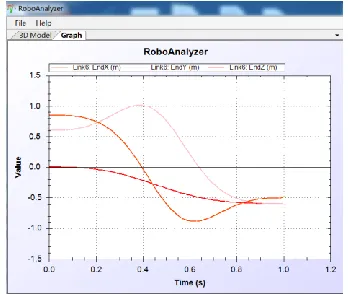
From the initial pose to the end pose, the simulation time is designed as 1s and the simulation step number is 100, so
the run trajectory of robot from initial position to the end position on the x, y, and z direction is shown in the
[image:4.612.81.255.198.345.2]Figure 2:
Figure 2. The forward kinematics simulation diagram of robot B. The inverse kinematics simulation
The inverse kinematics is the process of using the known robot end pose to solve the value of each joint angle. T0 is
the initial end pose of robot, Tz is the end pose matrix of
robot. T0 and Tz are respectively:
1 0 0 0
0 1 0 0
6 . 0 0 0 1
85 . 0 0 1 0
0
T
1 0 0 0
12 . 0 808 . 0 0 5883 . 0
1 . 0 0 1 0
8 . 0 5883 . 0 0 8086 . 0
z
T
[image:4.612.326.564.305.444.2]And then put the D-H parameter of robot and the end pose matrix of robot into the simulation software, so that get the inverse solution, as shown in the Figure 3:
Figure 3. The inverse kinematics simulation diagram of robot
C. The robot dynamic simulation
Robot dynamic research is to solve the relationship between the robot's movement and the robot force, and robot dynamics analysis not only plays an important role in the robot structure design, but also affects the selection of actuator, and has a significance on the robot speed and the control of robot acceleration. First, according to the request of software, set the position of center of gravity of each link, links’ material density, acceleration of gravity, etc. And the force of each link in the process that the robot still run from the initial pose T0 to the end pose Tz of the robot.
But the main stress joints of robot are joint 2 and joint 3, only their stress condition are considering in the robot movement process, the results are shown in Figure 4:
Figure 4. The force (or torque) of joint 2 and joint 3 of robot
V. CONCLUSION
The kinematics and dynamics of the robot are the basis of robot research, so the paper analyzes the kinematics and dynamics of the robot, establishes robot kinematics model using D-H model, and analyzes the positive and inverse solution of the running model, and use the Lagrange equation for the kinetics analysis to conclude the relationship between the robot movement and the robot arm force. Finally, the paper adopts the simulation software to illustrate the problems in the robot kinematics and dynamics models which are difficult to understand, so that the correctness of the model is verified.
REFERENCES
[1] LUO Jia-Jia, HU Guo-qing. Study on the Simulation of Robot Motion Based on MATLAB. Journal of Xiamen University (Natural Science) .44.5 (2005): 640-644.
[image:4.612.58.281.520.680.2]International Journal of Emerging Technology and Advanced Engineering
Website: www.ijetae.com (ISSN 2250-2459, ISO 9001:2008 Certified Journal, Volume 5, Issue 4, April 2015)
20
[3] Sun Xiaoyong, Xie Zhijiang, Jian Kailin, Zhang Jun. Dynamics Analysis and Simulation of 6-PSS Flexible Parallel Robot. Transaction of the Chinese Society for Agricultural Machinery, 2012, 43(7): 194-205.
[4] S K SAHA. Introduction to Robotics, CHINA MACHINE PRESS, 2009: 76 -145.
[5] Chen Lugang. Dynamics simulation study of welding robot based on Adams. Jiangnan university, 2012.
[6] LIU Yi-xiang, Li Rui-feng, LI Dong-wan.Dynamic Simulation Study on Application ADAMS for the Upper Arm of Welding Robot. Journal of Harbin University of Commerce Natural Sciences Edition, 2001 (3): 63-66.
[7] Liu Qifeng. The Dynamics Analysis and Structure Design of QianJiang welding robot,School of mechanical engineering zhejiang university, 2007.