International Journal of Emerging Technology and Advanced Engineering
Website: www.ijetae.com (ISSN 2250-2459,ISO 9001:2008 Certified Journal, Volume 4, Issue 3, March 2014)
760
Stress and Reduction Analysis of a Spur Gear Tooth
Mahesh. Badithe
1, Srimanthula Srikanth
2, Jithendra Bodapalli
31Student of M.Tech (CAD/CAM) in Dept. of ME, NCET College, Vegavaram
2 M.Tech (CAD/CAM) Asst.Professor, Dept. of ME, Pragati Engineering College, surampalem
3
Assoc. Professor and HOD, Dept. Of ME, NCET College, Vegavaram
Abstract— This paper describes Stress and Reduction analysis of a Spur gear. Gears are commonly used for transmitting power. They develop high stress concentration at the root and the point of contact. The repeated stressing on the fillets causes the fatigue failure of gear tooth. The main objective of this study is to add different shaped holes to reduce stress concentration. A finite element model of Spur gear with a segment of three teeth is considered for analysis and stress concentration reducing holes of various sizes are introduced on gear teeth at various locations. In the paper Static analysis of a 3-D model had been performed by using ANSYS 10.0. Analysis revealed that aero-fin shaped hole introduced along the stress flow direction yielded better results.
Finally Stress relieving feature having a shape of aero-fin is used in the path of stress flow which helped to regulate stress flow by redistributing the lines of force. This also yielded better results when compared to elliptical and circular holes. In this study, the best result is obtained by introducing aero-fin hole at (38.7653, 65.4083, and 0) and having scaling factor of 0.6. The result displayed a stress reduction by 50.23% and displacement reduction by 45.34%.
Keywords— Cast Iron spur gears, Static analysis, Stresses & Displacements of analyzed gears, Aero-fin hole.
I. INTRODUCTION
According to the position of axes of the shafts, the following are the different kinds of gears.
A). Parallel
Spur gear
Helical gear
Rack and pinion
B). Intersecting
Bevel gears
C). Non – Intersecting and Non parallel
Worm gears
The gear materials used for the manufacture of gears depend upon the strength and service conditions like ware and noise etc. The gears maybe manufactured from metallic or non – metallic materials.
The cast iron is widely uses for the manufacture of gears due to its good wearing properties, excellent machine ability and ease of producing complicated shapes by casting method. The non – metallic materials like wood, rawhide, compressed paper and plastic like Nylon, Acrylic and Polycarbonate etc are used for gears, especially for reducing weight and noise.
Weight reduction can be achieved primarily by the introduction of better material, design optimization and better manufacturing process. The plastic materials have corrosion, low electrical and thermal conductivity, easily formed into complex shapes, wide choices of appearance, colors and transparences. The introduction of plastic materials was made it possible to reduce the weight of the spur gear without any reduction on load carrying capacity and stiffness.
The Nylon materials have high strength, good mechanical and abrasion resistance property, excellent wear resistance, resistance to most chemical and self – lubricant. Polycarbonate materials have, high impact strength, good dimension stability and heat resistance. Since Nylon and poly carbonate have good properties as stated above the cast iron spur gears are analogized by ANSYS 10-0.
Gears are used for a wide range of industrial applications. They have varied application starting from textile looms to aviation industries. They are the most common means of transmitting power. They change the rate of rotation of machinery shaft and also the axis of rotation. For high speed machinery, such as an automobile transmission, they are the optimal medium for low energy loss and high accuracy. Their function is to convert input provided by prime mover into an output with lower speed and corresponding higher torque. Toothed gears are used to transmit the power with high velocity ratio. During this phase, they encounter high stress at the point of contact. A pair of teeth in action is generally subjected to two types of cyclic stresses:
i) Bending stresses inducing bending fatigue.
International Journal of Emerging Technology and Advanced Engineering
Website: www.ijetae.com (ISSN 2250-2459,ISO 9001:2008 Certified Journal, Volume 4, Issue 3, March 2014)
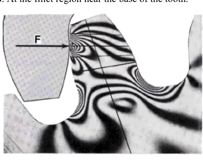
761 However, combined action of both of them is the reason of failure of gear tooth leading to fracture at the root of a tooth under bending fatigue and surface failure, due to contact fatigue. When loads are applied to the bodies, their surfaces deform elastically near the point of contact. Stresses developed by Normal force in a photo-elastic model of gear tooth the Fig.1.1. The highest stresses exist at regions where the lines are bunched closest together. The highest stress occurs at two locations: A. at contact point where the force F acts
[image:2.612.64.265.260.419.2]B. At the fillet region near the base of the tooth.
Fig 1 Photo-elastic Model of gear tooth
The surface failures occurring mainly due to contact fatigue are pitting and scoring. It is a phenomenon in which small particles are removed from the surface of the tooth due to the high contact stresses that are present between mating teeth. Pitting is actually the fatigue failure of the tooth surface. Hardness is the primary property of the gear tooth that provides resistance to pitting. In other words, pitting is a surface fatigue failure due to many repetitions of high contact stress, which occurs on gear tooth surfaces when a pair of teeth is transmitting power. Gear teeth failure due to contact fatigue is a common phenomenon observed. Even a slight reduction in the stress at root results in great increase in the fatigue life of a gear.
For many years, gear design has been improved by using improved material, hardening surfaces with heat treatment and carburization, and shot peening to improve surface finish etc. Few more efforts have been made to improve the durability and strength by altering the pressure angle, using the asymmetric teeth, altering the geometry of root fillet curve and so on. Some research work is also done using the stress redistribution techniques by introducing the stress relieving features in the stressed zone to the advantage of reduction of root fillet stress in spur 3 Gear. This also ensures interchangeability of existing gear systems.
The studies in which combination of circular and elliptical stress relieving features are used obtained better results than using circular stress relieving features alone which are used by earlier researchers. In this research work, an aero-fin shaped stress relieving feature is tried. A finite element model with a segment of three teeth is considered for analysis and a stress relieving feature of various sizes are introduced on gear teeth at various locations.
II. LITERATURE SURVEY
Investigators analyzing the gear tooth for stresses have done several studies: A.Manoj Hariharan [1] conducted stress analysis on 8 different gears by determining the highest point of contact for all gears. Stress analysis for the load contact point travelling along the involute curve is done for gears. The point of contact where maximum stress occurs is determined for all eight test gears and the variation of this H (Highest point of Contact) diameter for contact ratio greater than one is studied. Then the gear ratio where it is maximum is taken for application of force for all studies. From the results, he compared the stresses on each gear with their respective highest point of contacts and selected the weak gear among those for stress relief studies. He introduced circular holes as stress relieving features at different locations and also varied the diameters of holes. He concluded with an optimization study of drilling two circular holes, each on two mating teeth at the same location relative to each tooth, stress can be reduced. M.S.Hebbel, V.B.Math and B.G.Sheeparamatti [2] used elliptical and circular holes as a stress relieving feature. Analysis revealed that, combination of elliptical and circular stress relieving features at specific, locations are beneficial than single circular, single elliptical, two circular
or two elliptical stress reliving features.
Shanmugasundaram Sankar, Maasanamuthu Sundar Raj, Muthusamy Nataraj [3] did a study using circular root fillet instead of the standard trochoidal root fillet. The result reveals that the circular root fillet design is particularly suitable for lesser number of teeth in pinion and whereas the trochoidal root fillet gear is more opts for higher number of teeth.
Ashwini Joshi, Vijay Kumar Karma [4] did a work which deals with the effect on gear strength with variation of root fillet design using FEA. Circular root fillet design is considered for analysis. The loading is done at the highest point of single tooth contact (HPSTC). 5
International Journal of Emerging Technology and Advanced Engineering
Website: www.ijetae.com (ISSN 2250-2459,ISO 9001:2008 Certified Journal, Volume 4, Issue 3, March 2014)
762 Sorin Cănănău-Based [6] on an exact geometry design of the involute gear tooth, a set of profile gears is obtained in order to calculate the 2D contact. A stress analysis was performed for CAD profiles results using the finite element procedure. The paper investigates the 2D analysis versus 3D analysis for stress in the root region of teeth. By this approach, is also investigated the influence of non-uniform load along contact line to the fillet stress. Ali Raad Hassan [7] did a research study in which Contact stress analysis between two spur gear teeth was considered in different contact positions, representing a pair of mating gears during rotation. A programme has been developed to plot a pair of teeth in contact. Each case was represented a sequence position of contact between these two teeth. The programme gives graphic results for the profiles of these teeth in each position and location of contact during rotation. Finite element models were made for these cases and stress analysis was done. The results were presented and finite element analysis results were compared with theoretical calculations, wherever available. The idea of using holes to reduce stresses is not a new one. In 1990, Dippery [7] experimented with the use of supplementary holes in a structure as a method of reducing the stress concentration that was already present. His result showed that stress concentration reductions are possible in a generic shape using holes as stress relief.
III. SPUR GEAR
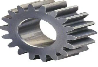
[image:3.612.340.540.312.491.2]Spur gears are the most common type of gears. They are used to transmit rotary motion between parallel shafts i.e., they are usually cylindrical in shape, and the teeth are straight and parallel to the axis of rotation. Sometimes many spur gears are used at once to create very large gear reductions. Spur gears are used in many devices but not in cars as they produce large noises
Fig 2 spur Gear
A) Conjugate Action:
Mating gear teeth against each other to produce rotary motion are similar to cams. When the tooth profiles are designed so as to produce a constant angular-velocity ratio during meshing, they are said to have conjugate action. A geometric relationship can be derived for the form of tooth profiles to provide conjugate action which is summarized as Law of Gearing as follows:
―A common normal to the tooth profiles at their point of contact must, in all positions of the contacting teeth, pass through a fixed point on the line-of-centers called the pitch point." 11
[image:3.612.89.255.556.669.2]Any two curves or profiles engaging each other and satisfying the law of gearing are conjugate curves.
Fig 3 conjugate action
When one curved surface pushes against another, the point of contact occurs where the two surfaces are tangent to each other (point c), and the forces at any instant are directed along the common normal ab to the two curves. The line ab, representing the direction of action of the forces, is called the line of action. The line of action will intersect the line of centers O-O at some point P. The angular-velocity ratio between the two arms is inversely proportional to their radii to the point P. Circles drawn through point P from each center are called pitch circles, and the radius of each circle is called the pitch radius. Point P is called the pitch point.
B)Tooth Profile:
I) Cycloidal:
International Journal of Emerging Technology and Advanced Engineering
Website: www.ijetae.com (ISSN 2250-2459,ISO 9001:2008 Certified Journal, Volume 4, Issue 3, March 2014)
763 The gear tooth profile is based on the epicycoid and hypocycloid curves, which are the curves generated by a circle rolling around the outside and inside of another circle, respectively. An advantage of the cycloidal teeth over the involute one is that wear of Cycloidal tooth is not as fast as with involute tooth. For this reason, gears transmitting very large amount of power are sometimes cut with cycloidal teeth. 1) Since the cycloidal teeth have wider flanks, therefore the cycoidal gears are stronger than the involute gears, for the same pitch. These are preferred for cast teeth. 2) In cycloidal gears, the contact takes place between a convex flank and concave surface, whereas in involute gears, the convex surface are in contact. This condition results in less wear in cycloidal wear and however the difference in wear is negligible. 3) The interference in cycloidal gears does not occur at all. Though there advantages of cycloidal gears they are outweighed by the greater simplicity and flexibility of the involute gears.
Ii) Involute:
[image:4.612.102.259.487.653.2]The involute gear profile is the most normally used system for gearing. In an involute gear, the profiles of the teeth are involutes of a circle. The involute of a circle is the spiraling curve traced by the end of an imaginary taut string unwinding itself from that stationary circle called the base circle. In involute gear design, contact between a pair of teeth occurs at a single instantaneous point. Rotation of the gears causes the location of this contact point to move across the respective tooth surfaces.
Fig 4 Involute profile of gear tooth
1) Involute teeth are very easy to manufacture and the actual distance between the centers may deviate slightly from the theoretical distance without affecting the velocity ratio or general performance. Because of this distinct advantage, gears with involute profile teeth are used more than those with cycloidal teeth.
2) In involute gears, the pressure angle, from the start of the engagement of teeth to its end remains constant. It is necessary for smooth running and less wear of gears. But in cycloidal gears, the pressure angle is maximum at the beginning of engagement, reduces to zero at pitch point, starts increasing again and becomes maximum at the end of engagement. This does not yield smooth running of gears. 3) The face and flank of involute teeth are generated by a single curve whereas in cycloidal gears, double curves are required for the face and flank respectively. Thus the involute teeth are 14 easy to manufacture than cycloidal teeth. The only disadvantage of involute teeth is that the interference occurs with pinions having smaller number of teeth.
C)Gear Geometry
Here we present the calculations for the gear we will use for our stress concentration reduction studies. Please note that this is the same gear geometry used by Hariharan[1]. As given in Shigley[8], the gear geometry calculations are as follows: Considering the pressure angle (φ) = 200 Pitch circle Dia. (PCD) = module(m) x no. of teeth Tooth thickness = (π x module) /2 Root fillet = 0.2 x module Addendum Dia.(Da)= PCD +2 x module Dedendum Dia.( Dd) = PCD – 2.5 x m Base circle dia. (Db) = PCD x cos φ
IV. PARAMETERS OF GEAR
Module (m) = 2 Pitch circle dia (d) = 50mm No. of teeth (N) = 25 Tooth thickness (t) = 3.14mm Root fillet = 0.628mm Addendum dia (Da) = 54mm Dedendum dia (Dd) = 45mm Base circle dia (Db) = 46.984mm Material used: Steel Properties of Steel: Young’s modulus = 21000 MPa Poison’s ratio = 0.3
V. GEAR DESING CALCULATION
International Journal of Emerging Technology and Advanced Engineering
Website: www.ijetae.com (ISSN 2250-2459,ISO 9001:2008 Certified Journal, Volume 4, Issue 3, March 2014)
764 The Dedendum (d) = 1.157/P = 1.157/6.28 = .18424 Outside Diameter (DO) = D+2*a = 50.318 Outside Radius (RO) = 25.159 Root Diameter (DR) = D-2*d = 1.1054 Root Radius (RR) =o.5527 For method [9] described below following calculations are also required: 1. Circumference of the Base circle, (CB) = Pi * (DB) = Pi * 46.984 = 147.6 2. 1/25th of the Base Circle Radius, (FCB) = .9396 3. Number of times that FCB can be divided into CB, (NCB) = 157.08 4. 360 degrees divided by NCB, (ACB) = 2.29 5. Gear Tooth Spacing (GT) = 360/T = 14.4 degrees.
VI. FINITE ELEMENT MECH GENERATION
A finite element mesh is a positioning of a given subset of the three-dimensional space by elementary geometrical elements of various shapes. The mesh generation is performed in the bottom-up flow i.e., lines are discretized first; the mesh of the lines is then used to mesh the surfaces; then the mesh of the surfaces is used to mesh the volumes. In this process, the mesh of an entity is only constrained by the mesh of its boundary. For example, in three dimensions, the triangles discretizing a surface will be forced to be faces of tetrahedra in the final 3D mesh only if the surface is part of the boundary of a volume. This automatically assures the conformity of the mesh. Every meshing step is constrained by a ―size field‖ (sometimes called ―characteristic length field‖), which Gmsh 2.7 prescribes the desired size of the elements in the mesh. This size field can be uniform or specified by values associated with points in the geometry.
Gmsh is good at:
Generating 1D, 2D and 3D simplicial finite element meshes for CAD models in their native format.
Specifying target element sizes accurately. It provides several mechanisms to control the size of elements in the final mesh: through interpolation from sizes specified at geometry points and using flexible mesh size fields.
Running on low end machines and machines with no graphical interface.
Visualizing and exporting computational results in great variety of ways.
Creating simple extruded geometries and meshes with the help of respective commands.
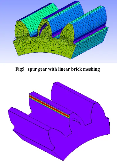
[image:5.612.346.545.143.418.2]Fig5 spur gear with linear brick meshing
Fig 6 Spur gear loaded at HPSTC
VII. PROBLEM DEFFINITION
International Journal of Emerging Technology and Advanced Engineering
Website: www.ijetae.com (ISSN 2250-2459,ISO 9001:2008 Certified Journal, Volume 4, Issue 3, March 2014)
765
a)Laminar flow analogy:
For relieving stress concentration in gears conventional methods used are making Fillets, Notches and Holes.
The flow analogy is used to visualize the stress concentration. It gives us a physical picture of why and where stress concentration exists and it can be used as a tool to decrease stress concentration. The path of flow analogy in gear starts from highest point of application of load and ends at the root fillet of the tooth. This indicates that lines of force travel from contact 32 point to root fillet, with gradual decrease in width of the flow pattern. So, the stress concentration is more at the fillet region which causes breakage of the tooth. The problem of stress concentration is solved by removing material in the path of stress flow analogy. When the material is removed in the path of flow analogy, the lines of force will travel uniformly. In our experiment, the material is removed in the shape of an aerodynamic fin which decreased the maximum principal stress at the fillet.
b)Significance of Aero-fin hole:
The shape of aero-fin selected for this study is such that it modifies the stress flow into a smoother way, i.e., smoother flow of stress is achieved best by an aero-fin type of design because the curvy nature of this helps stress flow lines of stress to find a fluent path without any interruptions, the shape becomes narrowed towards the fillet end which will help the stress lines to flow smoothly to the fillet without increasing stresses.
VIII. RESULTS
i) Stresses & Displacements of analyzed gears
The gear without hole is examined to determine the maximum stress at the fillet and then the aero-fin hole is introduced to gear. The position and size of the aero-fin hole can be varied by changing input values of center of one of the arcs of hole and scaling factor using Parameterization in Gmsh. Now, the gear is experimented with different modifications done to the aero-fin hole by varying the parameters mentioned above. The stresses and displacements are calculated and analyzed so that the maximum stress at the fillet is reduced which is the main aim of this project. 33
[image:6.612.62.271.179.327.2]The Fig illustrates the co-ordinates of a focus point. It is considered as the center of aero-fin hole which is used for transformation of entire hole.
Fig 7 Centre of aero-fin hole
International Journal of Emerging Technology and Advanced Engineering
Website: www.ijetae.com (ISSN 2250-2459,ISO 9001:2008 Certified Journal, Volume 4, Issue 3, March 2014)
[image:7.612.48.290.319.519.2]766
Fig 8 Stress and displacement in Normal Gear
The maximum stress at the fillet is 168Mpa which much higher compared to the applied load on the gear.
[image:7.612.342.545.445.673.2]Results of the analyzed gears are tabulated
Table 1
Results of the analyzed gears
According to the results tabulated above, the decrease in stress is 50.23%, whereas in the reference thesis[1] stress is reduced by 24.07%. From this it can be inferred that aero-fin hole serves better as a stress relieving feature compared to circular hole.
iii) Stress and displacement in Gear 1(with aero-fin hole)
Fig9: Gear 1 [table 1]
The maximum stress at the fillet is 98.3Mpa after the introduction of aero-fin hole with a scaling factor of 0.75
iv) Stress and displacement in Gear 2 (with aero-fin hole):
International Journal of Emerging Technology and Advanced Engineering
Website: www.ijetae.com (ISSN 2250-2459,ISO 9001:2008 Certified Journal, Volume 4, Issue 3, March 2014)
767 The maximum stress at the fillet is 93.7MPa, which is obtained by changing the position of hole and unvarying the scaling factor. 38
[image:8.612.54.271.177.349.2]v)Stress and displacement in Gear 3 (with aero-fin hole):
Fig 11: Gear 4 [table 1]
The maximum stress at the fillet is 85.8MPa. The stress is decreased by decreasing the scaling factor to 0.6.
vi) Stress and displacement in Gear 5 (with aero-fin hole):
Fig 12: Gear 5 [table 1]
The maximum stress at the fillet is decreased to 83.6MPa with the scaling factor of hole as 0.6. The stress obtained is approximately half of the stress without aero-fin hole.
[image:8.612.336.544.195.410.2]IX. GRAPHS
Fig: 13 scaling vs stress
From the above graph it can be concluded that as the size of hole decreased, stress induced in the gear decreased significantly due to the modulation of hole in the stress flow direction.
Fig 14: scaling vs displacement
[image:8.612.58.290.406.687.2] [image:8.612.346.538.473.646.2]International Journal of Emerging Technology and Advanced Engineering
Website: www.ijetae.com (ISSN 2250-2459,ISO 9001:2008 Certified Journal, Volume 4, Issue 3, March 2014)
768
X. CONCLUSION
The main aim of the above study is to relieve stress from the maximum value to as minimum as possible. So the highest point of contact of teeth is selected as pressure application point which causes highest stress. Stress relieving feature having a shape of aero-fin is used in the path of stress flow which helped to regulate stress flow by redistributing the lines of force. This also yielded better results when compared to elliptical and circular holes. In this study, the best result is obtained by introducing aero-fin hole at (38.7653, 65.4083, 0) and having scaling factor of 0.6. The result displayed a stress reduction by 50.23% and displacement reduction by 45.34%.
Scope for further work:
Some more positions of the aero-fin shape can be experimented.
This can be extended to Bi-directional gears.
REFERENCES
[1] R. Yakut, H. Düzcükoğlu*, M.T. Demirci Mechanical Education
Department, University of Selcuk, Campus, Konya, Turkey, Received 30.09.2009; published in revised form 01.11.2009
[2] K. Mao, A new approach for polyamide composite gear design,
Wear 262 (2007) 432-441.
[3] M.H. Tsai, Y.C. Tsai, A method for calculating static transmission
errors of plastic spur gears using fem evaluation, Finite Elements in Analysis and Design 27 (1997) 345-357.
[4] C.H. Kim, Durability improvement method for polyamide spur
gears, Tribology International 39 (2006) 1454-1461.
[5] S. Senthilvelan, R. Gnanamoorthy, Effect of rotational speed on the
performance of unreinforced a glass fibre reinforced nylon 6 spur gears, Materials and Design 28 (2007) 765-72.Analysis‖. and Testing Materials Science, 12 (3), 2006, 220-225. 10.2 Books:
[6] Machine drawing by N.D.BHATT
[7] Machine design by S.M.D.JALALUDEEN.
[8] Design data book compiled by PSG College of Technology,
COIMBATORE.
[9] Machine design by BANDARI.
[10] Theory of machines by KHURMI.
[11] Van Me lick , H.G.H. ― Tooth Bending Effects in plastic Spur
Gears,‖ Gear Technology.
[12] White, J., D . Walton and D.J. Weale. ―The Beneficial effect of Tip
Relief on Plastic Spur Gears,‖ ANTEC Conf. Proc. Society Plastics Engineers (1998).
[13] Rosler, J. ―Zur Tragfahigkeitssteigerung Thermoplasticher
Zahnrader mit Fullstoffen,‖ PhD thesis, berlin University of Technology, 2004.
[14] Plastic Gears are more reliable when engineers account for material


![Fig 11: Gear 4 [table 1]](https://thumb-us.123doks.com/thumbv2/123dok_us/8718077.883437/8.612.58.290.406.687/fig-gear-table.webp)
