TOWARDS A COMPACT ELECTRO-PNEUMATIC ACTUATED ARM FOR MOBILE ROBOTS
G.S. Walsh, C. McGinn and K. Kelly
Department of Mechanical and Manufacturing Engineering, Trinity College Dublin.
ABSTRACT
The design, control and the issues surrounding an electro-pneumatic actuated arm for mobile robots is presented. The design is a 3 degree-of-freedom arm incorporating a DC geared motor, a Festo DMSP fluidic muscle-spring couple, and a high torque servo motor. The main issues with conventional robotic arms are the need for high ratio transmissions and large joint torques caused by inherently bulky motors. The design presented in this paper greatly reduces the joint friction torque that contributes to the dangers associated with these traditional robot arms, with the use of compliant fluidic muscles. Reducing these dangers is desirable in mobile robot applications as the industry is becoming more focused on safe human-machine interaction and collaboration. A review of current state of the art research and design of arms incorporating fluidic muscles is presented. While these designs demonstrate great compliant behaviour, they are unpractical for use in mobile robotic applications due to the huge number of these actuators. A PI controller is utilised, taking in the joint angles of the arm as inputs. A number of tests are undertaken to benchmark the performance of the arm. The arm is capable of performing inverse kinematics and a user input of a position in x-y co-ordinates computes a set-point for the PI controller. The performance and controllability of the arm is analysed using the generated angle response data. A number of design modifications are suggested for improved performance for future work.
KEYWORDS: Robotics, Pneumatic Muscle, Inverse Kinematics
1.
INTRODUCTION AND BACKGROUNDis a primary objective. The safety issue primarily involves mitigating impact load from unexpected collisions between robot and human. Robots that employ compliant drive trains, which include compliant actuators, are inherently safe since they do not produce the large impact loads associated with high impedance designs. Although safety can be achieved by the strict limitation of the power and velocity of high performance manipulators, as is done in medical devices, an innovative scheme must be developed to make general purpose robots safe in human environments.
1.1. ACTUATOR CHOICE
The two main types of actuators that are utilised in the arm design are DC motor and pneumatic fluidic muscles.
A majority of today’s robots use electric motors as their actuation method. As small electric motors produce moderately small torques, they are commonly used together with reduction gears to increase torques as well as large pulleys to meet the joint torque requirement. Unfortunately, this results in robots that have high effective inertia, since the inertia is proportional to the square of the gear reduction ratio[4]. Universal Robotics [5] are pioneering safe and accurate collaborate robotics with their use of motor force-feedback control strategies. These strategies are promising for the future of collaborative robots, but for mobile robot applications, a lighter actuator choice would be more desirable. Pneumatic actuators are extensively used in industry, mainly for simple repetitive tasks due to their compactness, power-to-weight ratio and simple operation. Various types of pneumatic actuators used in industrial environment are cylinders, pneumatic motors, pneumatic stepper motors and fluidic muscles. Problems related to the accuracy of control and nonlinearities associated with these actuators have prevented their widespread use in high precision robotic systems. The demand for lightweight actuators has encouraged technological improvements and innovations in modern pneumatic actuators and components, and well as in control strategies. A less traditional type of pneumatic actuator and popular alternative to the traditional cylinder is the Pneumatic Artificial Muscle (PAM). This actuator was first invented in the 1950s by the physician, Joseph McKibben and was used in orthotic appliances for polio patients[6]. PAMs consist of an internal bladder surrounded by a braided mesh that is attached at either end to fittings. When the PAM is supplied with compressed air at the inlet, the internal bladder tends to increase in volume against the braided mesh shell, which in turn causes the actuator to shorten and produce pulling forces if a load is applied[7].
Figure 1: Static force vs contraction ratio of a DMSP 20N actuator [9]
These actuators have been extensively employed in industrial automation, but their use in the development of complaint robotics can be found in the literature. To move the load in both directions an antagonistic coupling should be used. Two antagonistic pneumatic artificial muscles, or a coupled spring, can drive a rotational element in a similar way to how the skeletal biceps and triceps rotate the forearm around the elbow. The bio-inspired ‘Airics’ arm, developed by Festo[10] utilises 30 DSMP fluidic muscles, built-up in antagonistic pairs, which move the bone structure, much like a human arm. This arm can be considered the state of the art in terms of anthropomorphic, natural and compliant movement. The ZAR3[11] is another example of a compliant, human like arm which utilises 12 Festo MAS fluidic muscles. Although both of these robots incorporate an elegant design and demonstrate great controllability, however, for mobile robot applications these designs are impractical due to the demanding compressed air requirement and weight associated with the large number of solenoid valves.
1.2. CONTROL STRATEGIES
As stated, the complex nonlinear dynamics of the PAM make it a challenging system for control design. The problems with the time variance, compliance, high hysteresis and nonlinearity of pneumatic systems have made it difficult to realize precise position control[12]. In order to obtain suitable control performance, the effect of non-linear factors contained in the PAM must be considered. Various control methodologies have been applied to control different robot arms and manipulators driven by artificial muscles. Pack[13] describes and compares three different control strategies, PID, PID tuned by a fuzzy supervisor and nonlinear feedback controller. The test rig used in this study contains two Festo DMSP muscles in an antagonistic setup and utilizes the Chou-Hanaford model in the control code for force estimation. Simulations show that the PID controller gives a slow response, while the best response is given by the nonlinear feedback controller. The use of learning control algorithms can be found in the literature. A feed-forward control of a non-linear PAM system using fuzzy logic is proposed by Balasubramanian and Rattan [14]. A fuzzy inverse dynamics controller was designed and tested for trajectory tracking capabilities. A problem with the fuzzy method is the difficulty in constructing a control rule’s bases in practice.
2. DESIGN CONCEPT
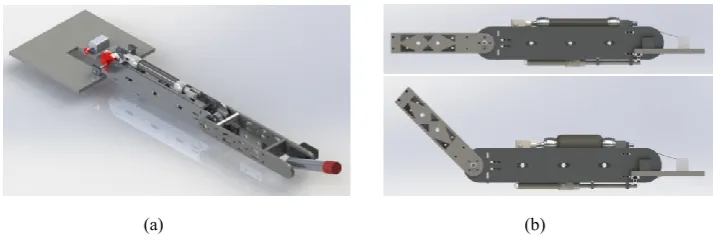
Addressing the limitations found in the literature, a prototype solution for an electro-pneumatic arm has been proposed and developed. The solution is a planar arm with three links. The first link is actuated by a geared DC motor, the second link utilises a pulley actuated by a Festo DMSP-20 fluidic muscle coupled with an extension spring, and the final joint is actuated by a high-torque servo motor. The first link consists of an aluminium structural support member with a light aluminium shell mounted to the outside. The structural member allows the gear that is being driven by the motor to be mounted to the end while also accommodating a threaded mounting block for the fluidic muscle. The second link consists of a PVC shell with an aluminium support structure and the last link is a simple aluminium tube actuated by a high torque servo. This link has not been fully developed yet and is in the design purely for control development. The whole arm assembly (not including the base or DC motor) weighs 1.8 kg. The fluidic muscle design allows for a compact and evenly distributed weight in the first link, reducing the moment arm and torque requirement of the DC motor. The range of motion and joint torque generated by a pneumatic muscle are trade-offs since the maximum contraction of the pneumatic muscle is limited up to 25% of its fully stretched length. The requirements of range of motion and torque determine the choice of the pulley radius and initial pneumatic muscle length. The muscle length chosen is 150mm, which allows a range of movement from 0-75o.
Figure 2: CAD rendering of arm design: a) Full arm design assembly, b) Working principle of pneumatic muscle-spring coupled joint.
Link Length Mass COM (M) Weight Torque
1 0.42m 1.6kg 0.167m 15.696N 8.71N-m
2 0.32m 0.46kg 0.102m 4.5126N 6.23N-m
[image:4.477.60.417.363.481.2]3 0.153m 0.2kg 0.75m 1.962N 1.49N-m
Table 1: Link Characteristics
3. DESCRIPTION OF TEST APPARATUS
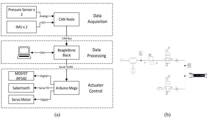
The schematic diagram of the test apparatus is illustrated in Figure 3(a) and 3(b). Figure 3(a) illustrates the control hardware, which can be divided into three distinct parts; data acquisition, data processing and actuator control. The data processing part consists of a low-level GPIO microcontroller board, utilising an Atmel 328 8-bit MCU. This GPIO is connected to two MPU6050 inertial measurement units (I2C connection) and two Honeywell 24PC Series pressure sensors (analog connection). The data acquired is sent to the data processing part using a CAN protocol. The data processing part consists of a Beaglebone Black linux computer connected to a laptop over an SSH connection. The control software is coded in ‘C++’ programming language. All of the processing for the inverse kinematics, PI controllers and actuator commands is done on the Beaglebone Black. The actuator commands are sent to the actuator controller via a serial connection. The actuator controller consists of an Arduino Mega that is connected to a Sabertooth motor driver, a MOSFET IRF540 (pneumatic actuator control) and a Turnigy 1259TG servo motor.
[image:5.477.63.422.402.611.2]Figure 3(b) illustrates the pneumatic system used. The compressed air is supplied by small compressor and is controlled by a control loop on the main controller that turns it on/off at different pressure thresholds. The pressure in the tank is read through a Honeywell 24PC Series pressure sensor. A 2/2 Matrix 720 electrically controlled solenoid valve is used for controlling the inlet. These solenoids are controlled using the MOSFET IRF540. For variable control of the flow a PWM signal is sent to them. A manual flow restrictor is attached after the first and before the last solenoid valve. This allows for fine tuning of the air flow going in and out of the Fluidic Muscle.
Figure 3: Test Apparatus: a) Control Hardware, b) Schematic of pneumatic system
Pressure Sensor x 2
IMU x 2
CAN Node
BeagleBone Black
Arduino Mega Sabertooth
MOSFET IRF540
Analog
I2C
CAN Bus
Serial TX/RX
Digital
Serial TX SSH
Servo Motor Digital
Data Acquisition
Data Processing
Actuator Control
4. PERFORMANCE TESTS
A PI controller is employed that uses the joint angles from the MPU6050 IMU. An inverse kinematic model for the arm has been developed, allowing an x-y positional set-point to be chosen. An objective of this research is to investigate whether a simple PI controller, using a single input of a joint angle can be implemented to get, acceptable positional control of the arm. A number of preliminary tests were completed to appropriately tune the PI controller. For each of the performance tests, an x-y co-ordinate was input into the main control program, which generated angle set-points for the joints. Before the data is input the robot moves to a default position and once the angle set-points have been established, joints attempt to reach those set-points. Data for the angles and end-effector position was recorded at a frequency of 100Hz.
5. RESULTS
The results from a selection of performance tests are shown in Figure 4. For the motor actuator, P=0.9 and I=0.2, and for the fluidic muscle, P=0.8 and I=0.4. In each case, Theta1 is the DC motor and Theta2 is the fluidic muscle. The servo was not included in these results as it is assumed it reaches its set-point. Figure 4(a) and 4(c) represents the DC motor going towards the set-point of -41.5 o and the fluidic muscle going towards a set-point of 55o. From Figure 4(a) it is evident that this goal is reached somewhat satisfactory. Comparing this result to Figure 4(b), where the DC motor is travelling to a set-point of -7.9o and the fluidic muscle going towards 52.3o, it is evident that the set-point for the fluidic muscle is not satisfactorily reached. This is most likely due to the effects of gravity acting on the arm, which were negated in controllability tests conducted in the literature. While the PI tuning parameters are sufficient for the results in Figure 4(a), they do not appear appropriate for Figure 4(b). This would suggest that another controller approach needs to be taken, such as a self-tuning PID controller or the development of a dynamic control model. The results also show that the movement of the arm isn’t very smooth. There is also the possibility of mechanical backlash from the DC motor and the pulley. This is expected as this design is early in the development stage. Some further work and testing on the controller and some mechanical modifications to the design will hopefully rectify this problem.
(a) (b)
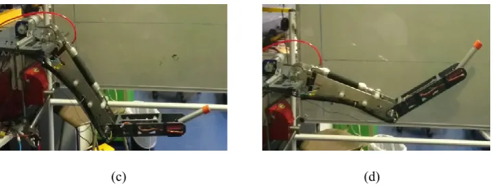
Figure 4: (a) Joint output for set-point (-41.5 o, 55o
, 9.63o), (b) Joint output for
set-point (-7.9o, 52.3o
, 22o), (c) and (d) Still images of arm final position during testing.
6. DESIGN MODIFICATIONS FOR FUTURE DESIGN
There are a number of mechanical modifications and further controller testing required in order for this arm to be used on a mobile robot.
In terms of the mechanical design, a problem with spring backlash in the fluidic muscle-spring coupled joint is highlighted. This backlash causes the joint to oscillate when the joint velocity is too great. This could be rectified with the addition of additional springs of greater stiffness or a damping mechanism in the form of a gas strut. The addition of a second fluidic muscle in an antagonistic setup with the existing would improve the overall control accuracy of the system by removing the spring backlash, while also increasing the range of motion of the joint. This antagonistic setup has been explored in the literature [15,16] with favourable results, although the control problem becomes a complex one. While this design is robust, a few modifications could be made to reduce the weight. The aluminium shell could be replaced with a lighter material like carbon fibre, as could the main support member in the first link. The current design adds a lot of unneeded inertia to the system which is not ideal when the end goal is human interaction.
The third joint needs to be developed further as the current one was for testing purposes only. This joint needs to be able to incorporate a manipulator for the next stage of this research project.
Further control testing is required for the next stage of development, and developing a dynamic model of the system is required to obtain accurate controllability of the system.
7. CONCLUSION
A novel robot arm has been developed that deals with the issues surrounding compactness, weight and the need for large compressed air supply, that were presented in the literature. The compact design of the fluidic muscle link allows for an evenly distributed weight, reducing the overall torque and moment arm requirements on the DC motor. Some issues are evident in the accurate control of
[image:7.477.63.423.60.198.2]the system, and will require further testing or development of alternative control methods to achieve desirable results.
8. REFERENCES
1. J. Liu, Y. Zhang ZL. Improving the positioning accuracy of a
neurosurgical robot system. IEEE/ASME Trans. Mechatronics, vol. 12, no. 5, pp. 527–533, Oct. 2007. .
2. Nishida NK and K. Perceptual control based on prediction for natural communication of a partner robot. EEE Trans. Ind. Electron., vol. 54, no. 2, pp. 866–877, Apr. 2007. .
3. A. Khanicheh, D. Mintzopoulos, B. Weinberg, A. A. Tzika and CM. Magnetic resonance compatible smart hand rehabilitation device for brain imaging. IEEE Trans. Neural Syst. Rehabil. Eng., vol. 16, no. 1, pp. 91– 98, Feb. 2008. .
4. Vaculik SA. A Framework for Electromechanical Actuator Design. PhD Thesis, The University of Texas at Austin; 2008.
5. Universal Robots UR3 Arm Is Small and Nimble, Helps to Build Copies of Itself - IEEE Spectrum.. Available from:
http://spectrum.ieee.org/automaton/robotics/industrial-robots/universal-robots-ur3-robotic-arm. [cited 2015 May 7]
6. Kelasidi E, Andrikopoulos G, Nikolakopoulos G, Manesis S. A Survey on Pneumatic Muscle Actuators Modeling, pp. 1442–1452, June 2012.
7. Wickramatunge KC, Leephakpreeda T. Study on mechanical behaviors of pneumatic artificial muscle. Int. J. Eng. Sci. Elsevier Ltd; pp. 188–198, Feb 2010.
8. http://www.festo.com/cms/en_corp/9790.htm., [cited 2015 May 05].
9. Festo catalog, Fluidic muscle DMSP/MAS, http://www.festo.com. [cited 2015 May 05].
10. http://thefutureofthings.com/5695-festos-bionic-arm/, [cited 2015 May 05].
11. Boblan I, Bannasch R, Schwenk H, Prietzel F, Miertsch L, Schulz A. A Human-Like Robot Hand and Arm with Fluidic Muscles : Biologically Inspired Construction and Functionality, pp. 160–179, June 2004.
13. R.T. Pack, M. Iskarous and K. Kawamura. Comparison of fuzzy and nonlinear control techniques for a flexible rubbertuator-based robot joint. International Fuzzy Systems and Intelligent Control Conference, pp. 361– 370, Oct 1994.
14. Balasubramanian K. Fuzzy Logic Control of a Pneumatic Muscle System Using a Linearizing Control Scheme, pp. 432–436, June 2003.
15. Yu H, Huang S, Chen G, Thakor N. Control design of a novel compliant actuator for rehabilitation robots. Mechatronics. Elsevier Ltd; 2013 Dec [cited 2014 Nov 30];vol 23, pp. 1072–1083, Dec 2013.
![Figure 1: Static force vs contraction ratio of a DMSP 20N actuator [9]](https://thumb-us.123doks.com/thumbv2/123dok_us/8810557.918311/3.477.93.336.29.149/figure-static-force-vs-contraction-ratio-dmsp-actuator.webp)