For Peer Review
Wavelet-based Individual Blade Pitch Control for Vibration Control of Wind Turbine Blades
Journal: Structural Control and Health Monitoring Manuscript ID STC-18-0132.R1
Wiley - Manuscript type: Research Article Date Submitted by the Author: n/a
Complete List of Authors: Fitzgerald, Breiffni; University of Dublin Trinity College, Civil, Structural and Environmental Engineering
Staino, Andrea; Trinity College Dublin, School of Engineering Basu, Biswajit; Trinity College Dublin, Civil Engg
Keywords: vibration control, wind turbine, wavelet, LQR, wind energy, pitch control
For Peer Review
DOI: xxx/xxxxRESEARCH ARTICLE
Wavelet-based Individual Blade Pitch Control for Vibration
Control of Wind Turbine Blades
Breiffni Fitzgerald*
1| Andrea Staino
1,2| Biswajit Basu
11School of Engineering, Trinity College
Dublin, Dublin, Ireland
2PHM Centre of Excellence, Alstom SA,
93400 Saint-Ouen, France
Correspondence
*Breiffni Fitzgerald, Department of Civil, Structural and Environmental Engineering, School of Engineering, Trinity College Dublin, Ireland. Email: [email protected]
Summary
This paper proposes a novel individual blade pitch control strategy with the
objec-tive of reducing blade vibration. A wavelet linear quadratic regulator (LQR) control
algorithm which is an advanced modification of the conventional LQR controller has
been developed for this purpose. The formulation of the modified LQR algorithm
uses the information derived from wavelet analysis of the blade response in
real-time to obtain the local energy distribution over frequency bands. This information,
reflecting the effect of excitation on the blades, is used to design the pitch controller
by updating the weighting matrices to be applied to the response energy and the
con-trol effort. The proposed concon-trol algorithm does not requirea priorichoice of the weights as in the classical case and calculates the gains using the weights based on
the response characteristics in real time. The optimal LQR control problem is solved
for each time interval with updated weighting matrices, through the Ricatti equation,
leading to time-varying gain matrices. Simulations are carried out using the National
Renewable Energy Laboratory’s (NREL) high-fidelity FAST wind turbine simulation
model. The simulations indicate that the proposed new wavelet controller achieves
significant reduction in the out-of-plane response of the blades as compared to
stan-dard LQR or industry stanstan-dard proportional integral (PI) controllers, at the expense
of minor increases in rotational speed variability and increased pitch actuator usage.
KEYWORDS:
Wind turbine, Wavelet, LQR, Vibration control, Pitch control
1
INTRODUCTION
The development of wind energy technology over the past two decades has been remarkable. The Global Wind Energy Council (GWEC) reports that by the end of 2016 487GW of wind power have been installed globally, this represents a capacity increase of greater than 550% over the last decade [9]. This increase in capacity has been made possible largely through advancements in wind turbine technology. The trend of the past decade has been for larger turbine blades and towers to maximise power extraction from the wind resource. Commercial wind turbines are commonly rated at greater than 5MW today with blade and tower lengths greater than 65m and 100m respectively. The current state-of-the-art wind turbine is a 9.5MW machine with 80m long blades and a hub height of 105m. The increasing size of the blades and towers has led to increased flexibility in these components. This has in turn led to vibration problems due to the dynamic nature of the environment in which the structures operate in and the material characteristics of the structures. Over ten years ago Ahlstrøm [1] demonstrated that large turbine vibrations have a
0Abbreviations:LQR, linear quadratic regulator; PI, proportional integral;
Structural Control and Health Monitoring
For Peer Review
major influence on power production and this work highlighted the need to control blade vibrations as the scale of wind turbines increases. Dueñas-Osorio and Basu [11] have also shown that excessive vibration of turbine towers can have damaging effects on equipment located in the nacelle that is sensitive to acceleration. The need for vibration mitigation strategies for modern HAWTs has therefore been well established.
The past decade has seen structural control approaches applied to HAWTs to control vibrations in blades and towers. Passive [30, 32, 38, 39], semi-active [2, 13, 24, 29, 7, 31] and active [18, 16, 14, 15, 19, 36, 33] control schemes have been proposed by various researchers. However, all of these approaches share a similar weakness - they require additional hardware and control systems to be installed on the wind turbine blade or tower and for this reason the wind industry has been reluctant to implement many of these controllers.
In parallel with the application of structural control schemes to HAWTs, in recent years researchers have have also investigated blade pitch control strategies for aerodynamic load control. Pitch control strategies modify the aerodynamic load experienced by wind turbine blades and have been used to regulate the power production of HAWTs by adjusting the rotational speed. Regulating the aerodynamic load in this way helps to curb the fatigue damage induced in blades due to cyclic loading. Bossanyi pioneered this work, in particular with the concept of individual blade pitch control (as opposed to standard rotor collective pitch control)[5],[6]. Other researchers have also developed pitch controllers with dual objectives of regulating rotor speed and reducing fatigue loads/vibration in wind turbine towers/blades [28], [27]. Such studies on pitch control have shown that by controlling the aerodynamic load experienced by the blades/tower the vibration of the component can also be controlled. Staino and Basu have stated that load control and vibration control are very closely related although they seem different [35]. As such, pitch control strategies can now be considered as an alternative means to reduce vibrations and fatigue loads and associated damage in wind turbine components. Pitch control strategies also utilise existing sensors and actuators on the wind turbine. These controllers operate without the installation of auxiliary damping devices, actuators and controllers thus making them more acceptable to industry and more easily implementable.
This paper proposes a novel individual blade pitch control strategy with the objective of reducing blade vibration. A wavelet linear quadratic regulator (LQR) control algorithm which is an advanced modification of the conventional LQR controller has been developed for this purpose. Information obtained from wavelet analysis of blade out-of-plane responses is used to obtain the local energy distribution over frequency bands. This information is used to design the pitch controller by updating the weighting matrices to be applied to the response energy and the control effort. The optimal LQR control problem is solved for each time interval with updated weighting matrices, through the Ricatti equation, leading to time-varying gain matrices. The new controller has been developed in MATLAB/SimulinkR and implemented on the National Renewable Energy Laboratory’s (NREL) state-of-the-art FAST wind turbine simulator. The simulations indicate that the proposed new wavelet controller achieves significant reduction in the out-of-plane response of the blades as compared to standard LQR or industry standard proportional integral (PI) controllers. The vibration reductions are achieved at the cost of minor increases in rotational speed variability as well as increased actuator usage.
2
WIND TURBINE MODEL
A wind turbine model is necessary to illustrate the application of the wavelet-based LQR controller to pitch control. The FAST (fatigue, aerodynamics, structures and turbulence) simulation code [21] is used in this paper to simulate the response of the wind turbine. FAST is an open source design code developed by NREL. FAST has been used in numerous previous studies ([17], [37], [3], [8], etc.) to model the structural dynamics of wind turbines. MATLAB/SimulinkR is used for the control design and implementation with FAST. The specifications of the NREL 5-MW baseline reference wind turbine [23] have been used to model the turbine in FAST. This is a three-bladed upwind turbine whose properties were derived from available data on commercial wind turbines. The main properties of the 5-MW baseline turbine are listed in Table 1 . FAST performs nonlinear aero-servo-elastic analysis in the time domain by joining rotor aerodynamics, electrical system dynamics and strutural dynamics modules [22].
3
CONTROL DESIGN AND IMPLEMENTATION
The focus of this study is to minimize the out-of-plane response of the wind turbine blades using the blade pitch control system. This section gives a description of the three controllers used in the analysis.
For Peer Review
TABLE 1 Properties of NREL 5-MW baseline HAWT [23]
Max. rated power: 5-MW
Rotor orientation, configuration: Upwind, 3 blades Rotor diameter: 126 m
Hub height: 90 m
Cut-in, rated, cut-out wind speed: 3 m/s, 11.4 m/s, 25 m/s Cut-in, rated rotor speed: 6.9 rpm, 12.1 rpm
Rated generator speed: 1173.7 rpm Blade operation: Pitch to feather Max. blade pitch rate: 8 deg/s Rated generator torque: 43,093 Nm Max. generator torque: 47,402 Nm
FIGURE 1 Conventional HAWT control architecture
3.1
Baseline PI controller
The main objectives for control of wind turbines are power regulation (e.g. power maximization, power saturation, smoothing, etc.), speed regulation (e.g. noise restriction), load mitigation (e.g. limiting structural loads/fatigue on blades, on mechanical components, etc.), safety and compliance (e.g. decoupling of mechano-electrical dynamics, compliance to national grid-codes, etc.). In most modern HAWTs two control systems are designed to achieve these control objectives: a generator-torque controller and a rotor-collective blade pitch controller. The control architecture for such a conventional operational commercial HAWT is shown in Figure 1 . This type of machine is a variable speed pitch controlled wind turbine. This paper considers turbine operation in above rated conditions (Region 3) when pitch control is operational. In Region 3 the rotor speed is regulated by shedding extra aerodynamic power. Generator torque is held constant at the rated value. As wind speed increases, the blades are pitched towards incoming wind (“pitch to feather”) with the effect of decreasing the aerodynamic angle of attack. Classical Proportional-Integral-Derivative (PID) controllers are used to drive rotor speed error,Ω𝑒to zero, this is shown in Figure 2 .
FAST have designed a baseline controller for the 5MW reference wind turbine based on this conventional design approach. Full details of the controller can be found in [23]. The rotor-collective blade pitch angle commands are computed using gain scheduled proportional-integral (PI) control on the speed error between the generator speed and the rated generator speed (1173.7
Structural Control and Health Monitoring
For Peer Review
FIGURE 2 Conventional PID pitch controllerFIGURE 3 Flowchart of the FAST baseline control system [23]
rpm). The control flow diagram for the FAST 5MW baseline controller is shown in Figure 3 , taken from the definition of the NREL 5MW wind turbine [23].
In this paper we have implemented the baseline PI controller in MATLAB/SimulinkR. This controller is used in this paper as a conventional controller for the purposes of comparison with the newly developed controllers.
3.2
Wind turbine model linearization
A model-based design (MBD) approach has been employed in this paper for the development of the state-feedback pitch con-trollers, namely the wavelet-based controller and the LQR controller. In the MBD control framework, the synthesis of the control law is based on an appropriate mathematical model that describes the dynamics of interest of the plant under consideration. In the study carried out in this paper, a suitable linear model representative of the dynamics of the wind turbine “plant” has been
For Peer Review
derived using FAST. FAST is a nonlinear aeroelastic code that accounts for nonlinearities in the wind turbine structural dynam-ics. For controller design in a MBD framework it is useful to use linearized state matrices that are representations of the complete nonlinear HAWT code. The FAST code has the capability of linearizing the HAWT model about a periodic steady state oper-ating point. LTI state matrices are output for use in controller design [21]. For the purpose of synthesizing the wavelet-based LQR pitch controller and the LQR pitch controller, the state matrices calculated in FAST are used to formulate an optimization problem whose solution provides, at each time step, the control signal to be implemented for pitch control of the rotor blades.
FAST perturbs each of the system variables about an operating point value to numerically linearize the nonlinear system equations of motion. The operating point values are associated with a steady condition of the wind turbine. This leads to a second-order linearized set of equations of motion [21]:
𝑀Δ
̄ ̈ 𝑞+𝐶Δ
̄ ̇𝑞+𝐾Δ
̄ 𝑞=𝐹Δ
̄ 𝑢+𝐹𝑑Δ
̄
𝑢𝑑 (1)
where𝑀 =𝑀|𝑜𝑝is the mass matrix,𝐶 = 𝜕
̄ 𝑓
𝜕 ̄
̇𝑞|𝑜𝑝is the damping/gyroscopic matrix,𝐾 = [ 𝜕𝑀
𝜕 ̄ 𝑞𝑞̄̈+
𝜕𝑓 𝜕
̄
𝑞]|𝑜𝑝is the stiffness matrix,
𝐹 = [𝜕𝑀𝜕
̄ 𝑢 ̄
̈ 𝑞+ 𝜕𝑓𝜕
̄
𝑢]|𝑜𝑝is the control input matrix, and𝐹𝑑 = − 𝜕
̄ 𝑓
𝜕 ̄̇𝑢 𝑑
|𝑜𝑝is the wind input disturbance matrix. ̄
𝑞is the vector of DOF displacements, (and
̄ ̇𝑞and
̄ ̈
𝑞are the DOF velocities and accelerations), ̄
𝑢is the vector of control inputs, ̄
𝑢𝑑is the vector of wind input “disturbances”, and𝑡is time. The|𝑜𝑝notation is used to signify that the partial derivatives are computed at the operating point. In state space form the linearized equations become:
̇𝑥=𝐴𝑥+𝐵Δ
̄ 𝑢+𝐵𝑑Δ
̄ 𝑢𝑑
𝑦=𝐶𝑥+𝐷Δ
̄ 𝑢+𝐷𝑑Δ
̄
𝑢𝑑 (2)
where the state vector is given by𝑥={Δ
̄
𝑞 Δ
̄
̇𝑞}𝑇 and the state derivative vector, ̇𝑥, is its first time derivative.
By running FAST in linearization mode the following state matrices are output: state matrix𝐴, control input matrix𝐵, wind input disturbance matrix𝐵𝑑, control input transmission matrix𝐷, wind input disturbance transmission matrix𝐷𝑑and output state matrix𝐶. This enables controller design in an MBD framework.
3.3
Wavelet controller
The application of a wavelet multi-scale controller has been proposed for vibration mitigation via blade pitch regulation. A formulation was presented in Basu and Nagarajaiah [4] for seismic vibration control of structures by applying active forces. Inspired by the time-frequency control concept, a wavelet based formulation has been developed in this paper focussing on a MIMO system for wind turbine structural load control using individual blade pitch regulation. The proposed time-frequency wavelet-LQR controller is based on a modified form of the linear quadratic regulator (LQR) problem constrained to a band of frequency in the wavelet domain. The fundamental idea of the proposed controller consists of adjusting the weightings for the conventional LQR controller depending on the desired frequency bands required to be controlled. To compute the control in the time domain a multi-resolution analysis (MRA) based discrete wavelet transform (DWT) is used, with the application of frequency band-dependent gains to different filtered signals at different frequency bands. In this study, the control gains are chosen to be time-invariant for each frequency band (although they can be updated online for adaptive applications); however, since the controller works at multiple time scales, the control signal implemented corresponds to a time varying control gain.
As detailed in [4], DWT implementation may be attained using orthogonal filter banks. Appropriate sampling of the dila-tion (scale) parameter ‘𝑎’ in logarithmic scale leads to the discrete sequence{0, 𝑎1, ..., 𝑎𝐿, ..., 𝑎𝑗, ..., 𝑎𝐽}, where each scale𝑎𝑗 corresponds to a specific band of frequencies.
For the wavelet-based pitch controller developed in this paper, the state vector𝑥(𝑡)is defined as
𝑥(𝑡) = [𝑂𝑂𝑃1(𝑡) 𝑂𝑂𝑃2(𝑡) 𝑂𝑂𝑃3(𝑡) 𝐹 𝐴(𝑡)
̇
𝑂𝑂𝑃1(𝑡) 𝑂𝑂𝑃̇ 2(𝑡) 𝑂𝑂𝑃̇ 3(𝑡) 𝐹 𝐴̇ (𝑡)]𝑇 (3)
where𝑂𝑂𝑃𝑗(𝑡)is the out-of-plane displacement of the𝑗𝑡ℎblade and𝐹 𝐴(𝑡)is the fore-aft displacement of the tower.
The control input vector𝑢𝑤(𝑡)is defined as
𝑢𝑤(𝑡) = [𝛽𝑤,⋆1(𝑡) 𝛽𝑤,⋆2(𝑡) 𝛽𝑤,⋆3(𝑡)] (4)
where𝛽⋆
𝑤,𝑗(𝑡), 𝑗= 1,2,3indicate the pitch command to be sent to the pitch actuator for the Blade𝑗.
Structural Control and Health Monitoring
For Peer Review
The𝑛𝑡ℎorder state equation for the linearized wind turbine system is of the form
̇𝑥(𝑡) =𝐴𝑥(𝑡) +𝐵𝑢𝑤(𝑡), 𝑡≥0, 𝑥(0) =𝑥0
𝐴∈ℝ𝑛×𝑛, 𝐵 ∈ℝ𝑛×𝑚 (5)
where𝑥(𝑡)is the state vector, as defined in Equation 3, and𝑢𝑤(𝑡)is the control input vector, as defined in Equation 4. The𝐴and 𝐵linearized system matrices are obtained from FAST (see Equation 2). The objective is to design a controller such that:
i. The closed-loop system is asymptotically stable
ii. The quadratic cost functional𝐽𝑎
𝑗 is minimized
For the synthesis of the controller in the time domain, using DWT and multi-resolution analysis (MRA) reconstruction, the state of the system can be decomposed into time signals resolved at different frequency bands and it can be expressed as:
𝑥(𝑡) =𝑥𝐿𝑎
𝑗(𝑡) +
𝐾
∑
𝑗=𝐿 𝑥𝑗𝑎
𝑗(𝑡) (6)
where𝑥𝐿𝑎
𝑗(𝑡)is a low frequency signal approximation of the states (below frequencies corresponding to scale given by𝑎=𝑎𝐿) and𝑥𝑗𝑎
𝑗(𝑡)are wavelet filtered signals obtained at scale𝑎=𝑎𝑗. The parameter𝐾 in Equation 6 indicates the frequency above which the energy content in the signal can be ignored (i.e. it is assumed that𝑥(𝑡)is a finite energy signal). The reconstructed wavelet control signal is eventually expressed as
𝑢𝑤(𝑡) =𝐺𝑤𝐿𝑥𝐿𝑎
𝑗(𝑡) +
𝐾
∑
𝑗=𝐿 𝐺𝑤𝑗𝑥𝑗𝑎
𝑗(𝑡) (7)
where the controller𝐺𝑤𝐿(a scalar) is synthesized for frequency bands𝑎 < 𝑎𝐿and the controllers𝐺𝑤𝑗 (scalar) are synthesized
for frequency bands𝑎=𝑎𝑗,𝑗=𝐿, ..., 𝐽.
The wavelet controller determines for each band of frequencies associated with the scale𝑎=𝑎𝑗the controller gains such that
the functional
𝐽𝑎
𝑗 =
+∞
∫
0 𝑥𝑎
𝑗(𝑡)
𝑇𝑅
1𝑎𝑗𝑥𝑎𝑗(𝑡) +𝑢𝑎𝑗(𝑡)
𝑇𝑅
2𝑎𝑗𝑢𝑎𝑗(𝑡) (8)
where𝑥𝑎
𝑗(𝑡),𝑢𝑎𝑗(𝑡)are wavelet filtered signals obtained at scale𝑎=𝑎𝑗 for the state and for the control input, respectively. The objective function in Equation 8 is a quadratic functional as in the case of a conventional LQR but valid for wavelet filtered signals at a frequency band with dilation parameter𝑎𝑗.
The matrices𝑅1𝑎𝑗 and𝑅2𝑎𝑗 are weighting matrices such that𝑅1𝑎𝑗 ≥ 0and𝑅2𝑎𝑗 > 0.𝑅1𝑎𝑗 is a weight applied to the states of the system that penalizes the distance of system states from the equilibrium.𝑅2𝑎
𝑗 is a weight applied to the control effort that penalizes the control input (actuator force), in the minimization process. The objective of the controller is to drive the states of the system from 𝑥0 towards the equilibrium by using a minimum amount of energy, according to a dynamics that can be influenced by choosing appropriate weighting matrices𝑅1𝑎𝑗 and𝑅2𝑎𝑗. The synthesis of the controller is carried out by appropriately assigning the weights𝑅1𝑎
𝑗 and𝑅2𝑎𝑗 depending on the specific spectral components of the system response to be suppressed. The weighting matrices𝑅1𝑎𝑗 and𝑅2𝑎𝑗 are also dependent on a corresponding specific frequency band. Hence, this makes it possible to vary the weighting matrices for different frequency bands in order to choose the most appropriate design for the controller. For each scale 𝑎𝑗, the wavelet controller is obtained by solving the associated Algebraic Riccati Equation
constrained to the frequency band associated with the scale𝑎𝑗.
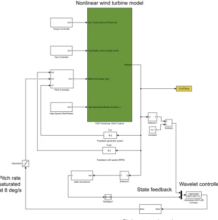
Figure 4 shows the implementation of the wavelet controller with FAST in MATLAB/SimulinkR.
3.4
LQ controller
For comparison, a standard linear quadratic approach has been used for individual blade pitch control. The design of the controller is based on the linear wind turbine model with state matrices𝐴and𝐵 (see Equation 2) obtained from FAST as described in Section 3.2. The LQR algorithm is a model based control strategy for linear systems in the state-space domain that guarantees closed-loop stability and robustness [26]. In the infinite-horizon LQ control design framework, given an𝑛𝑡ℎ order stabilizable
For Peer Review
Feedback LSS speed (RPM) Feedback generator speed
Pitch rate saturated at 8 deg/s
Nonlinear wind turbine model
Pitch actuator dynamics
State feedback Wavelet controller Out1
Yaw Controller
Out1
Torque Controller
In6
In2
In1
Out1
Pitch Controller
Out1
High-Speed Shaft Brake
Gen. Torque (Nm) and Power (W)
Yaw Position (rad) and Rate (rad/s)
Blade Pitch Angles (rad)
High-Speed Shaft Braking Fraction (-) OutData
FAST Nonlinear Wind Turbine
f(u) Fcn
f(u) Fcn5
xbar x
state reconstruct
U Y
Selector2 Saturation
Beta* Beta
Reshape1
Interpreted MATLAB Fcn Interpreted MATLAB
Function Subtract
12.1 Constant
U Y
[image:8.595.126.554.66.498.2]Selector1
FIGURE 4 Wavelet based individual blade pitch controller - Controller schematic
linear system in the form
̇𝑥(𝑡) =𝐴𝑥(𝑡) +𝐵𝑢𝐿𝑄(𝑡), 𝑡≥0, 𝑥(0) =𝑥0
𝐴∈ℝ𝑛×𝑛, 𝐵∈ℝ𝑛×𝑚 (9)
where𝑥(𝑡)is the state vector and𝑢𝐿𝑄(𝑡)is the control input vector, the objective of the design is to determine the matrix gain 𝐺𝐿𝑄such that the full-state feedback control law𝑢𝐿𝑄(𝑡) = −𝐺𝐿𝑄𝑥(𝑡)satisfies the following criteria:
i. The closed-loop system is asymptotically stable
ii. The quadratic cost functional𝐽 = 1
2∫ +∞ 0 [𝑥(𝑡)
𝑇𝑅
1𝑥(𝑡) +𝑢𝐿𝑄(𝑡)𝑇𝑅2𝑢𝐿𝑄(𝑡)]is minimized
The matrices𝑅1and𝑅2are weighting matrices with𝑅1≥0and𝑅2 >0.𝑅1defines a penalty on the states and𝑅2defines a penalty on control effort (actuator force).𝐽is the cost function that sums the penalties, if the state is not in the desirable location 𝐽 will be large. The LQR algorithm minimises𝐽 to give an optimal gain𝐺𝐿𝑄. Therefore, the main aim of the LQ regulator
Structural Control and Health Monitoring
For Peer Review
is to drive the states of the system from their initial values towards the desired equilibrium by using a minimum amount of energy, according to a dynamics that can be influenced by choosing appropriate𝑅1and𝑅2.𝑅1is positive semi-definite and𝑅2 is positive definite, these matrices are usually diagonal. The ratios of elements in𝑅1and𝑅2are typically increased or decreased by powers of 10 [12]. Increasing𝑅1increases the penalty on individual states and decreasing𝑅2 reduces the penalty on the actuator control force. If the couple(𝐴, 𝐵)is controllable (or at least stabilizable, i.e. non-controllable modes are stable), it can be shown that the controller𝑢𝐿𝑄(𝑡)that satisfies i. and ii. is given in the closed form:
𝑢𝐿𝑄(𝑡) =𝑅−12 𝐵𝑇𝑃 𝑥(𝑡) =𝐺𝐿𝑄𝑥(𝑡) (10)
where the matrix𝑃 is obtained by solving the algebraic Riccati equation (ARE):
𝐴𝑇𝑃 +𝑃 𝐴−𝑅1𝑃 𝐵𝑅−12 𝐵𝑇𝑃 +𝑅1 = 0 (11)
4
NUMERICAL SIMULATIONS
The nonlinear aeroelastic HAWT model has been simulated using the specifications of the NREL 5-MW baseline reference wind turbine described by [23]. Simulations have been carried out using FAST in MATLAB/SimulinkR to illustrate the capabilities of the proposed pitch control strategies. All simulations are 600 s as is standard in the wind turbine literature.
The wind acting on the wind turbine is represented as a steady flow including wind shear effects due to the rotation of the blade and turbulence. The turbulent wind field has been generated using the TurbSim package. TurbSim is a stochastic, full-field, turbulent-wind simulator. It numerically simulates time series of three-dimensional wind velocity vectors at points in a vertical rectangular grid [25]. The TurbSim output is then be used as input to FAST. In this paper we consider a value of 10% for the turbulence intensity. We have assumed a Kaimal spectrum and have used a different random seed to generate each turbulent wind file.
A Rayleigh distribution (i.e Weibull distribution with shape factor𝑘 = 2) has been assumed to describe the probabilistic behaviour of the wind speed. The Latin Hypercube Sampling (LHS) method [34] has been used to ensure that a uniform spread of sampling points across the wind speed range has been generated. The Rayleigh distribution has been partitioned into 200 areas of equal probability to generate wind speed samples in the range [11.4, 25] ms−1(corresponding to the Region 3 operation of the machine, [23]). The above rated wind speed range has been chosen in order to ensure operation of the wind turbine in the pitch controlled region. The realizations of the random variable associated with the wind speed are assigned without replacement to the dynamic model in FAST to calculate the vibrational response of the rotor blades subjected to the turbulent wind loads.
For each pitch control strategy developed in the present paper, the design of the controller has been carefully chosen as explained below.
i. The PI baseline controller has been tuned as reported in [20], with proportional gain = 0.01882681 and integral gain = 0.008068634.
ii. For the design of the LQR pitch controller, the choice of the weight𝑅1= 500 × [𝐼]3×3and𝑅2= 500 × [𝐼]3×3provides the best performance in terms of vibration reduction and pitch rate variation. These weights have been chosen after a number of trials which have led to the selection of the above mentioned design.
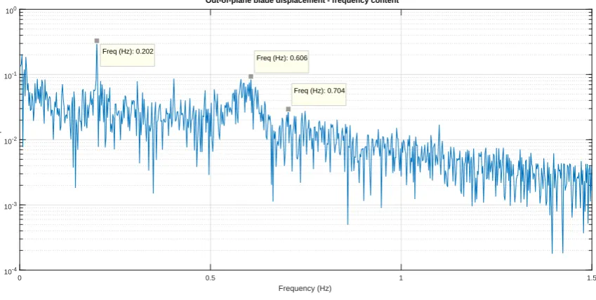
iii. For the design of the wavelet-LQR pitch controller, from the Fourier amplitude of the relevant degrees of freedom in Figure 5 it can be seen that most of the vibrational energy is localized in the low frequency range of the spectrum. The rated rotational speed of the turbine, 12.1 rpm (0.2 Hz), is known as the fundamental rotational (1P) frequency, this is clearly identified in Figure 5 . The blade passing (3P) frequency of the rotor, 0.6 Hz, is also clearly identified. Most of the vibrational energy is concentrated around 0.6 - 0.7 Hz corresponding to the natural out-of-plane frequency of the blade at 0.68 Hz [23]. Hence, the primary objective of the controller is to reduce the energy in the frequency band below 0.7 Hz which mainly contributes to the out-of-plane vibration of the blade. At each level, the filtered states are decomposed into linear combinations of basis functions using the orthogonal wavelet ‘db4’ from the Daubechies wavelets [10]. For the system considered, the states (Equation 3) are decomposed into 8 levels. The detail signals correspond to frequency bands with central frequencies from 0.6 Hz to 0.7 Hz. The reconstructed approximation signal at Level 8 covers all the frequency bands with central frequency less than 0.7 Hz. In order to achieve a better system response compared to conventional LQR, the weight on the control effort is set as𝑅2= 50 × [𝐼]3×3for the low frequency bands corresponding to the approximation
For Peer Review
0 0.5 1 1.5
Frequency (Hz)
10-4
10-3
10-2 10-1
100
Fourier amplitude
Out-of-plane blade displacement - frequency content
Freq (Hz): 0.202
Freq (Hz): 0.606
[image:10.595.99.524.68.282.2]Freq (Hz): 0.704
FIGURE 5 Uncontrolled out-of-plane blade displacement - frequency content
15 16 17 18 19 20 21 22
Mean wind speed (m/s)
2.5 3 3.5 4 4.5 5 5.5 6 6.5 7 7.5
Max out-of-plane displacement (m)
LQ Baseline Wavelet
FIGURE 6 Max blade out-of-plane displacement for varied wind speeds
signal at Level 8. In this way, more emphasis is given to the peaks in the energy spectrum which mainly contribute to vibration of blades.
5
RESULTS AND DISCUSSION
The wavelet controller achieves impressive reductions in the out-of-plane displacement demand when the turbine is operating in Region 3 (above rated but below cut-out speed). The maximum out-of-plane tip displacement of the blades for different mean wind speeds for each of the pitch controllers is shown in Figure 6 . The wavelet controller achieves peak response reductions of up to 49% when compared to the baseline PI controller and 54% when compared to the traditional LQ controller. It is important
Structural Control and Health Monitoring
[image:10.595.174.413.337.534.2]For Peer Review
0 100 200 300 400 500 600Time (s)
-1 0 1 2 3 4 5 6 7 8 9
Out-of-plane blade displacement (m)
[image:11.595.177.412.67.258.2]LQ Baseline Wavelet
FIGURE 7 Blade out-of-plane displacement at rated conditions
to also view the time series of some of the key results. Figure 7 shows the time history out-of-plane tip response of the blades when the turbine is operating at rated conditions with a turbulence intensity of 10% for each of the controllers. It is clear that the mean blade response is reduced by the wavelet controller when compared with both LQ and PI control. The rms response of the blade is also reduced by 66% compared with LQ control and 47%.
5.1
Comparison of controllers
The PI pitch controller has rotor speed regulation as its control objective. Both the LQ and wavelet controller have blade vibration reduction as their control objective. All controllers have the constraint of a maximum pitch rate of 8 deg s−1. The objective of this work is to investigate whether blade vibration reduction improvement is possible with novel pitch controllers when compared to an industry standard (PI) controller. With this in mind two parameters are considered when comparing controllers; blade pitch rate and speed error.
The blade pitch rate is a measure used to demonstrate the frequency of the pitch actuator usage. A high blade pitch rate is indicative of high pitch actuator usage. The blade pitch rate for the LQ and wavelet controllers is saturated at the maximum allowable value of 8 deg s−1. However, the blade pitch rate for the PI controller is considerably lower with a mean of 1.4 deg s−1and a maximum value of approximately 2 deg s−1. This indicates that the impressive vibration reductions achieved by the wavelet controller come at the cost of higher actuator usage.
In the standard control case (as in the PI controller considered in this paper), the collective blade pitch is used to regulate the rotor speed. This paper concerns the NREL 5MW reference wind turbine operating in Region 3 (above-rated wind conditions). The rated rotor speed for Region 3 is approximately 12.1 rpm [23]. The rotor speed error provides a good indication of the power regulation. The rms rotor speed error for the baseline PI controller is 0.88 rpm. The rms rotor speed error for the wavelet controller is 1.38 rpm. Thus, the significant reduction in the out-of-plane blade vibration is possible with minor increases in the rotor speed error.
6
CONCLUSIONS
The results clearly show that the wavelet-based multi-resolution analysis with a careful choice of the design parameters allows efficient delivery of the control action and improves the dynamic response. The wavelet controller significantly reduces blade vibrations. The wavelet controller utilizes existing sensors and actuators on wind turbines (i.e. the pitch control system) to achieve these vibration reductions. In this sense it is more readily implementable than traditional structural control devices that
For Peer Review
have been developed for wind turbine vibration control. These devices require additional hardware and control systems to be installed on the wind turbine blade or tower and the industry has been reluctant to implement many of these controllers.
The fundamental compromise in using the wavelet controller is evident. It is possible to greatly reduce blade vibrations at the cost of higher pitch actuator usage and slightly increased rotor speed variability. Reductions in the out-of-plane blade vibrations of over 40% can be achieved with small increases in the rotor speed error. This is a trade-off that must be considered in the design of a turbine. However, it should be noted that the power delivered to electrical grids by wind energy is determined by wind farms, not individual, standalone wind turbines. Therefore, it is doubtful that the minor increases in individual wind turbine rotor speed error will be relevant when compared with the overal power variability of a wind farm [27].
References
[1] Ahlstrøm, A., 2006: Influence of wind turbine flexibility on loads and power production.Wind Energy,9, no. 3, 237–249, doi:10.1002/we.167.
URL http://dx.doi.org/10.1002/we.167
[2] Arrigan, J., V. Pakrashi, B. Basu, and S. Nagarajaiah, 2011: Control of flapwise vibrations in wind turbine blades using semi-active tuned mass dampers.Structural Control and Health Monitoring,18, no. 8, 840–851, doi:10.1002/stc.404. URL http://dx.doi.org/10.1002/stc.404
[3] Bakka, T. and H. R. Karimi, 2012: Robust dynamic output feedback control synthesis with pole placement constraints for offshore wind turbine systems.Mathematical Problems in Engineering,2012.
[4] Basu, B. and S. Nagarajaiah, 2008: A wavelet-based time-varying adaptive lqr algorithm for structural control.Engineering structures,30, no. 9, 2470–2477.
[5] Bossanyi, E., 2003: Individual blade pitch control for load reduction.Wind energy,6, no. 2, 119–128.
[6] — 2005: Further load reductions with individual pitch control.Wind energy,8, no. 4, 481–485.
[7] Caterino, N., 2015: Semi-active control of a wind turbine via magnetorheological dampers.Journal of Sound and Vibration,
345, 1–17.
[8] Churchfield, M. J., S. Lee, J. Michalakes, and P. J. Moriarty, 2012: A numerical study of the effects of atmospheric and wake turbulence on wind turbine dynamics.Journal of turbulence,13, no. 14, 1–32.
[9] Council, G. W. E., 2015: Global wind report: Annual market update.Global Wind Energy Council.
[10] Daubechies, I., 1992:Ten lectures on wavelets. SIAM.
[11] Dueñas-Osorio, L. and B. Basu, 2008: Unavailability of wind turbines due to wind-induced accelerations.Engineering Structures,30, no. 4, 885–893.
[12] Duriez, T., S. L. Brunton, and B. R. Noack, 2017:Machine Learning Control-Taming Nonlinear Dynamics and Turbulence. Springer.
[13] Fitzgerald, B., J. Arrigan, and B. Basu, 2010: Damage detection in wind turbine blades using time-frequency analysis of vibration signals.The 2010 International Joint Conference on Neural Networks (IJCNN), IEEE, 1–5.
[14] Fitzgerald, B. and B. Basu, 2013: Active tuned mass damper control of wind turbine nacelle/tower vibrations with damaged foundations.Key Engineering Materials, Trans Tech Publ, volume 569, 660–667.
[15] — 2014: Cable connected active tuned mass dampers for control of in-plane vibrations of wind turbine blades.Journal of Sound and Vibration,333, no. 23, 5980 – 6004, doi:https://doi.org/10.1016/j.jsv.2014.05.031.
URL http://www.sciencedirect.com/science/article/pii/S0022460X14004404
[16] — 2016: Structural control of wind turbines with soil structure interaction included.Engineering Structures,111, 131–151.
Structural Control and Health Monitoring
For Peer Review
[17] — 2017: A monitoring system for wind turbines subjected to combined seismic and turbulent aerodynamic loads.Structural Monitoring and Maintenance,4, no. 2, 175–194.
[18] Fitzgerald, B., B. Basu, and S. R. K. Nielsen, 2013: Active tuned mass dampers for control of in-plane vibrations of wind turbine blades.Structural Control and Health Monitoring, doi:10.1002/stc.1524.
URL http://dx.doi.org/10.1002/stc.1524
[19] Fitzgerald, B., S. Sarkar, and A. Staino, 2018: Improved reliability of wind turbine towers with active tuned mass dampers (atmds).Journal of Sound and Vibration,419, 103–122.
[20] Jonkman, J. M., 2008:Influence of control on the pitch damping of a floating wind turbine. National Renewable Energy Laboratory Denver, CO.
[21] Jonkman, J. M. and M. Buhl, 2005:FAST User Guide. NREL/EL-500-38230 (previously NREL/EL-500-29798), Golden, CO: National Renewable Energy Laboratory.
[22] Jonkman, J. M. and M. L. Buhl Jr, 2007: Development and verification of a fully coupled simulator for offshore wind turbines.45th AIAA Aerospace Sciences Meeting and Exhibit, 8–11 January 2007, Reno, NV, AIAA Meeting Papers on Disc.
[23] Jonkman, J. M., S. Butterfield, W. Musial, and G. Scott, 2009:Definition of a 5-MW Reference Wind Turbine for Offshore System Development. National Renewable Energy Laboratory, Technical Report, NREL/TP-500-38060, Golden, Colorado.
[24] Karimi, H. R., M. Zapateiro, and N. Luo, 2010: Semiactive vibration control of offshore wind turbine towers with tuned liquid column dampers using h infinity output feedback control.Control applications (CCA), 2010 IEEE international conference on, IEEE, 2245–2249.
[25] Kelley, N. D. and B. J. Jonkman, 2005: Overview of the TurbSim stochastic inflow turbulence simulator. National Renewable Energy Laboratory.
[26] Kwakernaak, H. and R. Sivan, 1972:Linear optimal control systems. Wiley, New York.
[27] Lackner, M. A., 2013: An investigation of variable power collective pitch control for load mitigation of floating offshore wind turbines.Wind Energy,16, no. 4, 519–528.
[28] Larsen, T. J., H. A. Madsen, and K. Thomsen, 2005: Active load reduction using individual pitch, based on local blade flow measurements.Wind Energy,8, no. 1, 67–80.
[29] Luo, N., C. Bottasso, H. R. Karimi, and M. Zapateiro, 2011: Semiactive control for floating offshore wind turbines subject to aero-hydro dynamic loads.International Conference on Renewable Energies and Power Quality (ICREPQâĂŹ11) Las Palmas de Gran Canaria (Spain), 13th to 15th April.
[30] Murtagh, P. J., A. Ghosh, B. Basu, and B. M. Broderick, 2008: Passive control of wind turbine vibrations including blade/-tower interaction and rotationally sampled turbulence.Wind Energy,11, no. 4, 305–317, doi:10.1002/we.249.
URL http://dx.doi.org/10.1002/we.249
[31] Sarkar, S. and A. Chakraborty, 2018: Optimal design of semiactive mr-tlcd for along-wind vibration control of horizontal axis wind turbine tower.Structural Control and Health Monitoring,25, no. 2.
[32] Si, Y., H. R. Karimi, and H. Gao, 2014: Modelling and optimization of a passive structural control design for a spar-type floating wind turbine.Engineering Structures,69, 168–182.
[33] Staino, A. and B. Basu, 2013: Dynamics and control of vibrations in wind turbines with variable rotor speed.Engineering Structures,56, 58–67.
[34] — 2013: Vibration control and reliability of wind turbines. Safety, Reliability, Risk and Life-Cycle Performance of Structures and Infrastructures - Proceedings of the 11th International Conference on Structural Safety and Reliability, ICOSSAR.
For Peer Review
[35] — 2015: Emerging trends in vibration control of wind turbines: a focus on a dual control strategy.Phil. Trans. R. Soc. A,
373, no. 2035, 20140069.
[36] Staino, A., B. Basu, and S. Nielsen, 2012: Actuator control of edgewise vibrations in wind turbine blades.Journal of Sound and Vibration,331, no. 6, 1233 – 1256, doi:10.1016/j.jsv.2011.11.003.
URL http://www.sciencedirect.com/science/article/pii/S0022460X11008819
[37] Stewart, G. M., M. A. Lackner, A. Robertson, J. Jonkman, A. J. Goupee, et al., 2012: Calibration and validation of a fast floating wind turbine model of the deepcwind scaled tension-leg platform.The Twenty-second International Offshore and Polar Engineering Conference, International Society of Offshore and Polar Engineers.
[38] Zhang, Z., B. Basu, and S. R. Nielsen, 2015: Tuned liquid column dampers for mitigation of edgewise vibrations in rotating wind turbine blades.Structural Control and Health Monitoring,22, no. 3, 500–517.
[39] Zhang, Z., J. Li, S. R. Nielsen, and B. Basu, 2014: Mitigation of edgewise vibrations in wind turbine blades by means of roller dampers.Journal of Sound and Vibration,333, no. 21, 5283–5298.
Structural Control and Health Monitoring
![TABLE 1 Properties of NREL 5-MW baseline HAWT [23]](https://thumb-us.123doks.com/thumbv2/123dok_us/8813172.919316/4.595.49.546.63.486/table-properties-nrel-mw-baseline-hawt.webp)
![FIGURE 3 Flowchart of the FAST baseline control system [23]](https://thumb-us.123doks.com/thumbv2/123dok_us/8813172.919316/5.595.147.459.56.541/figure-flowchart-fast-baseline-control.webp)