5
XI
November 2017
578
©IJRASET (UGC Approved Journal): All Rights are ReservedKarnataka, India
2
Professor, Department of P. G. Studies and Research in Applied Electronics, Gulbarga University, Kalaburagi-585106,
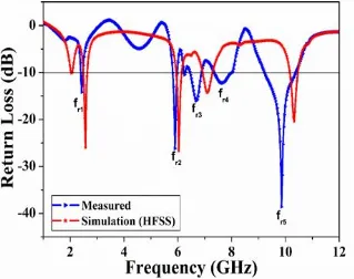
Abstract: in this paper, a novel design of the inset-fed circular microstrip antenna by inserting a modified U-slot on the patch and arrow mark slot in the ground is proposed. The antenna prototypes were simulated by Ansys HFSS software and measured practically. Low cost FR-4 dielectric substrate material with relative permittivity of 4.4 having physical dimension of 55.4 × 44 × 1.6 mm3 has been fabricated for validation with simulations. The proposed antenna resonates at five frequency points 2.4, 5.8, 6.7, 7.6 and 9.8 GHz with >-10 dB return loss having impedance bandwidths of BW1= 9.54% (2.32-2.55 GHz), BW2= 5.68% (5.73-6.07 GHz), BW3= 8.94% (6.39-6.99 GHz), BW4=10.71% (7.25-8.07 GHz), and BW5=13.36% (9.16-10.47 GHz). Virtual size reduction of 36.90% is achieved when compared to conventional antenna. The proposed antenna shows broadside radiation characteristics and finds application in WLAN (2.4/5.2/5.8GHz) and wireless communication.
Keywords: Inset-fed, U-slot, arrow mark slot, impedance bandwidth, penta-band, WLAN, wireless communication.
I. INTRODUCTION
Microstrip antennas (MSAs) offer many attractive features such as low-profile, light weight, planar configuration, ease of fabrication, conformable to planar and non-planar surfaces [1] etc. In the last four decades, the extensive technological work on MSAs have been developed for many wireless communication systems such as WLAN, Wi-Fi, sensors, satellite, broadcasting services, ultra-wideband (UWB), radio frequency identifications (RFIDs), reader devices, radars [2,3] etc. Still extendable work has been going on MSAs for modern wireless communication systems capable to work for applications such as portable, handheld devices, RFID reader devices which provide wireless networks. In the recent technological development, MSAs of smaller physical size are very much preferable to integrate in the systems especially operating at the lower microwave frequency ranges.
Moreover, the applications like land mobile telephony as well as in the field of WLANs [4, 5] further requirement would be a multi-frequency operations. So the designs of a printed antenna with intend to conform to multiple communications protocols, for example the IEEE 802.11b/g at 2.4 GHz and the IEEE 802.11a at 5.3 GHz and 5.8 GHz [6, 7] would be a challenging and difficult task for the designers.
In this paper, a novel design of inset-fed circular microstrip antenna by inserting a modified U-slot on the patch and arrow mark slot in the ground is proposed. The antenna is designed to work for penta-band operation covering different wireless communications. The details of the antenna design, simulation and experimental results are presented and discussed in next sections.
II. ANTENNADESIGN
The conventional circular inset-fed microstrip antenna in Fig. 1 and modified U-slot loaded on patch and arrow mark slot in the ground are designed by commercially available low cost FR-4 dielectric material with relative permittivity (εr) of 4.4 with thickness
579
©IJRASET (UGC Approved Journal): All Rights are Reserved [image:3.612.138.466.282.478.2]Fig. 1 Geometry of the conventional circular inset-fed microstrip antenna
Fig. 2 Geometry of the proposed penta-band inset-fed circular microstrip antenna
TABLEI
DIMENSIONS OF CONVENTIONAL AND PROPOSED ANTENNA
Antenna
parameters W L R Wf Lf IW IL h Ua Ul Uw Ub Ac AL Aw
Dimensions
(mm) 55.4 44 11.5 3.17 17.18 1.58 6.98 1.6 2.5 11 6 1 6.98 12 2
III.RESULTSANDDISCUSSION
580
©IJRASET (UGC Approved Journal): All Rights are ReservedFig. 3 Comparison of simulated and measured return lss characteristics of conventional circular inset-fed microstrip antenna
Fig. 4 Comparison of simulated and measured return loss characteristics of proposed penta-band circular patch antenna
[image:4.612.149.468.376.628.2]581
©IJRASET (UGC Approved Journal): All Rights are ReservedFig. 5 Simulated surface current distribution of the conventional antenna at 3.75 GHz
[image:5.612.130.486.266.456.2](a) (b)
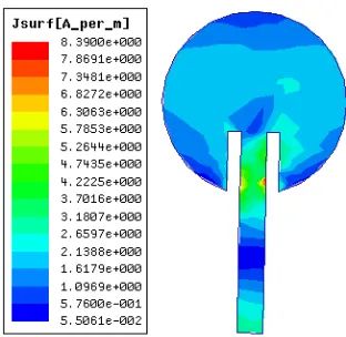
Fig. 6 Simulated surface current distributions of the proposed penta -band antenna observed at (a) 2.4 GHz, (b) 5.8 GHz
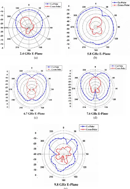
The desired normalized co-polarization and cross-polarization radiation pattern plots in E-plane at the resonating frequencies of the conventional antenna and proposed antennas are shown in Fig. 7 and Fig. 8(a)-(e). The radiation patterns are observed to be broadside in nature and linearly polarized at respective resonating frequencies. Also the proposed antenna exhibits similar radiation characteristics in its remaining operating frequencies.
[image:5.612.212.413.543.696.2]582
©IJRASET (UGC Approved Journal): All Rights are Reserved
(a) (b)
(c) (d)
[image:6.612.92.516.75.690.2](e)
583
©IJRASET (UGC Approved Journal): All Rights are ReservedIV.CONCLUSIONS
In this paper, a novel design of penta-band circular microstrip antenna is designed and developed. From the detailed experimental study, it is observed that by inserting U-slot on patch and arrow mark slot in the ground the antennas resonating at five different frequencies and achieved virtual size reduction of 36.90% when compared to conventional antenna without slots. The proposed antenna is compact in its structure and shows broadside radiation patterns. The measured and simulated results are in good agreement with each other. This antenna may find application in WLAN and wireless communication system.
V. ACKNOWLEDGMENT
The authors would like to express their sincere gratitude the authorities of Dept. of Science & Technology (DST), Govt. of India, New Delhi, for sanctioning the Vector Network Analyzer (VNA) to the Department of Applied Electronics, Gulbarga University, Gulbarga under the FIST project.
REFERENCES
[1] C. A. Balanis, Antenna Theory Analysis and Design, John Willey & Sons, New York, 2005. [2] Nasimuddin, Microstrip Antennas, In Tech Org., 2011.
[3] K. Siakavara, Methods to design microstrip antennas for modern applications in Microstrip Antennas, N. Nasimuddin (ed.), ch. 9 , pp. 173-236, In Tech Org., 2011.
[4] I. J. Bahl and P. Bhartia, Microstrip Antennas, MA: Artech House, 1982.
[5] Sheta, A. F., A. Mohra and S. F. Mahmoud, “Multi-band operation of compact H-shaped microstrip patch antenna”, Microwave Opt. Technol. Letter, Vol. 35, No. 5, 363-367, December 2002.
[6] Sheta, A. F., A. Mohra and S. F. Mahmoud, “Modified compact H-shaped microstrip antenna for tuning multi-band operation”, 25th National Radio Science Conference (NRSC2008), Tanta university, Tanta, Egypt, March 18-20
[7] Siddiqui Naushad Ather et al, “Truncated Rectangular Microstrip Antenna with H and U Slot for Broadband”, International Journal of Eng. Sc. and Techno., Vol. 5, No.01, pp 114-118, January 2013.