Solar Based Automatic Braking System using PLC
G. Jyothi1,T.Aparna Murthy2,K. Dharma Sai Shankar3, P.Yaswanth4, S.Chandra Sekhar5 1,2,3,4,5
B.Tech,EEE,Pragati Engineering College,India.
Abstract : In this project we show the concept of Automatic Braking System (ABS) by using sensor technology. Whenever vehicle moves on the road, if there is any sudden object appears then, sensor will sense the obstacle immediately and the vehicle reduces its speed gradually and choose probable path i.e.., right path, if there is also any obstacle in the new path, then the system offers braking .We attach this ABS for any type of braking system .In this concept we use one infrared sensor which sense the obstacle and transmit the signal in the air to the logical circuit to turn ON automatically. The entire supply to the system is given by the battery which is charged through the solar panel.
I. INTRODUCTION
Safety is a necessary part of man‘s life. Due to the accident cases reported daily on the major roads in all parts of the developed and developing countries, more attention is needed for research in the designing an efficient car driving aiding system. It is expected that if such a device is designed and incorporated into our cars as a road safety device. It will reduce the incidence of accidents on our roads and various premises with subsequent reduction in loss of life and property. However a major area of concern of an engineer should be safety. As it concerns the use of his/her inventions and the accompanying dangers due to human limitations. When it comes to the use of a motor vehicle. Accidents that have occurred over years tell us that something needs to be done about them from an engineering point of view.
In early version of electric vehicles with DC motors, a simple variable resistor type controller governed the acceleration and speed of the vehicle [1].
Avoiding collisions is a crucial issue in most transportation systems as well as in many other applications. The task of a collision avoidance system is to track objects of potential collision risk and determine any action to avoid or mitigate a collision.The task of any collision avoidance system is ultimately to avoid two or more objects from colliding[2]. This thesis presents theory for tracking and decision making in collision avoidance systems. The main focus is how to make decisions based on uncertain estimates and in the presence of multiple obstacles. A general framework for dealing with nonlinear dynamic systems and arbitrary noise distributions in collision avoidance decision making is proposed. It’s the maintenance cost of a vehicle that is looked upon. An automatic transmission in car is new to India it will take time to adapt. Hence an automatic braking system is adopted in order to eliminate the above mentioned problems. Regenerative braking takes place whenever the speed of the motor exceeds the synchronous speed. This baking method is called regenerative braking because here the motor works as generator and supply itself is given power from the load, i.e. motors [3].
II. PROPOSED TECHNIQUE
In this project we show the concept of Automatic Braking System (ABS) by using Programmable Logical Control (PLC) with sensor technology. Whenever vehicle moves on the road, if there is any sudden object appears then, sensor will sense the obstacle immediately, transmit the signal in the air to the PLC which activates logical circuit to turn ON automatically and gives necessary controlling action. i.e., the vehicle reduces its speed gradually and chooses probable path which may be right or left path, if there is also any obstacle in the new path, then the system offers braking .We attach this ABS for any type of braking system. The entire supply to the system is given by the battery which is charged through the solar panel.
III. MAIN OBJECTIVE
The objective of our paper is to minimize road accidents by considering the advantages of an early warning system where the driver is alerted of a possible collision with considerable amount of time before it occurs. In India, where safety, economy and time is of crucial value our cars suffer and more than the purchase. We know that brake is an equipment to reduce the speed of any moving or rotating equipment, like vehicles, locomotives. The process of applying brakes can be termed as braking[4].
at almost every possible area, be it in inside the motor used in factories, industrial areas or be it in locomotives or vehicles. Everywhere the use of mechanical and electrical brakes is inevitable. Here we are using logical braking by using of Programmable Logical Control (PLC) in the form of binary switching like in 1’s and 0’s.Whenever it is in motion the logical 1 is ON. If we require brake logical 0 will activated.
the Anti-Collision [5]device is a detection device meant to be incorporated into cars for the purpose of safety. As opposed to the anti-collision devices present in the market today, this system is not designed to control the vehicle. Instead, it serves as an alert in the face of imminent collision. The device is intendment to find a way to implement a minimum spacing for cars in traffic in a affordable way. It would also achieve safety for the passengers of a moving car. The device is made up of an infrared transmitter and receiver.
A. Features
1) Use of automatic braking system[6] comes with the advantages of avoiding road accidents, preventing the damage of vehicle body and smooth operations.
2) Use of programmable logic controller (PLC) serves as a digital computer which has been ruggedized and adapted for the control of manufacturing processes and ease of process fault diagnosis.
B. Overview
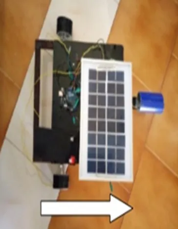
The idea consists of a Solar panel, Diode, Battery, Relay circuit, IR sensors, Motors and Arduino board. When sun rays falls on the grids of the solar cells, the solar cell converts the light energy to electrical energy by Photovoltaic effect and then solarpanel converted the solar energy to electrical energy, which is send to a rechargeable battery through the diode circuit. Here the diode circuit is placed to oppose the reverse flow of current into solar panel.The battery supplies the required voltage to the Arduino Board and motors. A relay circuit board is connected to Arduino board for triggering the relay circuitat the time of obstacle detection.The IR sensor is placed in front of the vehicle which is connected to the Arduino board, when an obstacle comes in front of the sensor, then the IR sensor senses that obstacle, and an error signal or a triggered voltage pulse is send to the Arduino board. The Arduino board receives that error or voltage signal and initiates the buzzer and stops the voltage or triggering input to the relays when the triggering signal or the voltage stops to the relay circuit, the coil of the relay stops energizing and the closed circuit becomes open circuit and the power supply of the motor becomes null and the motor stops rotating this will lead the vehicle into standby mode which is commonly known as braking.
C. Block Diagram
Fig 1 Block Diagram of Automatic Braking System (ABS)
motor is ON and the left side motor is in OFF state then the vehicle direction results in left similarly the left side motor is in on condition and the right side motor is in OFF condition then the vehicle direction will result in the right. If both the motors are ON in right and left respectively, then the vehicle direction results in straight line. The pictorial representation of the Block Diagram is as shown in the fig1.
IV. WORKING
The Hardware prototype consists of a Solar panel, Diode, Battery, Relay circuit, IR sensors, Motors and Arduino board as shown in fig 4. When sun rays falls on the grids of the solar cells, each solar cell converts the light energy to electrical energy of 0.18 volts by Photovoltaic effect and then solar panel converted the solar energy to electrical energy of 6 volts(6V), which is send to a rechargeable battery of 6 volts through the diode circuit. Here the diode circuit is placed to oppose the reverse flow of current into solar panel.The battery supplies the 6 volts to the Arduino Board and motors.
A voltage regulator is placed in the Arduino board which minimizes the output voltage to 5 volts. A relay circuit board is connected to Arduino board for triggering the relay circuit at the time of obstacle detection. The IR sensor is placed in front of the vehicle which is connected to the Arduino board. The IR sensor used in this project has a range of 8.7 cms and the range can be extended by adjusting potentiometer (POT). When an obstacle comes in front of the sensor, then the IR sensor senses that obstacle, and an error signal or a triggered voltage pulse of 3-5 volts is send to the Arduino board.The Arduino board receives that error or voltage signal and initiates the buzzer and stops the voltage or triggering input to the relays. When the triggering signal or the voltage stops to the relay circuit, the coil of the relay stops energizing and the closed circuit.
V. RESULT
The activities done by the hardware kit are given by,
A. Initially the vehicle starts by running the motors in forward direction as shown in figure 2 Normally a transmitted signal is send by a transmitting sensor. If an obstacle is sensed by the transmitting signal it sends the signal to microcontroller through a receiving sensor. Then the microcontroller sends a signal to relays to stop the forward operation of the motors
[image:4.612.215.397.475.709.2]B. As per the program dumped in micro-controller the buzzer is activated for alerting purpose. After alerting, the buzzer will turn-OFF and vehicle turns to its right by switching the relay of left motor into forward direction and also by switching the relay of the right motor in OFF condition for a time limit of 3000 milli seconds i.e.., three seconds(3sec). i.e.., the first motor is logically in binary “1” and second motor is logically in binary “0”. The above mentioned operation is as shown in figure 3 as follows,
Fig 3 : Vehicle moving in forward direction
Fig 4 : Vehicle turning towards left after sensing obstacle
C. Logical Inputs for Directions
Table 1: Logical Inputs for Directions
VI. CONCLUSION
As non- renewable energy sources goes on decreases, we are using renewable energy sources like solar panels to fulfil the energy requirement and to make the planet a eco green planet.
[image:5.612.188.424.449.649.2]By this project some of the disadvantages faced in the manual braking system can be overcome. The automatic braking system is benefit in many ways like it saves electrical energy, manpower, fuel and cost as braking is automatic.
REFERENCES
[1] Performance Measurement of Vehicle Crash Imminent Braking Systems Stanley Chien by M. Todd Moury, Glenn Widmann, Walter Kosiak, Lingxi Li and Yaobin Chen in Transportation Active Safety Institute (TASI) Indiana University-Purdue University Indianapolis 723 W. Michigan St., Indianapolis, IN 46202. In 2006.
[2] Automatic Collision Warning and Electro-Mechanical Braking System by Raj Reddy in International Journal on Emerging Technologies in 2015. [3] Fundamentals of Electrical Drives by Gopal.k.Dubey by Alpha Science publishers, 2nd edition, 2001 International Limited
[4] Evaluation of anti-lock braking systems effectiveness by David Burton, Amman Dadelaney in Royal Auto-mobile club of Victoria (RACV) Ltd. in April 2004. [5] Collision Avoidance Theory with Application to Automotive Collision Mitigation by Jonas Jansson in http://www.control.isy.liu.se of Linkoping University.in
2005.
[6] Automated Emergency Brake Systems Benefits by C Grover, I Knight, F Okoro, I Simmons, G Couper, P Massie, and B Smith in International Conference on Engineering Innovations and Solutions (ICEIS).in 2016.