3D Ultrasound Image Reconstruction Based on VTK
MAHANI HAFIZAH, TAN KOK, EKO SPRIYANTO
Department of Clinical Science and Engineering
University Technology of Malaysia
UTM Skudai, 81310 Johor
MALAYSIA
[email protected] http://www.biomedical.utm.my
Abstract: - Three dimensional (3D) ultrasound image reconstruction based on two dimensional (2D) images has become a famous method for analyzing some anatomy related to abnormalities. 3D ultrasound image reconstruction system is required in order to view the specific part of the object and so that it can be used for analysis purpose. In this paper, 2D images were taken by using untracked free-hand system. Few sets of 2D images were taken with different number of slices and after some 2D image processing, 3D reconstruction is done by using surface rendering techniques by implementing marching cubes algorithm in Visual C++ 6.0 with Visualization Toolkit (VTK) toolbox. From the experiment, we can conclude that in order to reconstruct a better 3D image, the aid of tracking sensor is important. Besides, another parameter such as the number of slices of the images and image processing technique will affect the smoothness of the reconstructed 3D image.
Key-Words: -2D ultrasound, 3D ultrasound, marching cubes, visualization toolkit (VTK)
1 Introduction
Medical imaging is the technique used to create images of the human body for clinical purposes especially for analyzing some anatomy related to abnormalities. Some of the commonly used imaging techniques are ultrasound, CT, and MRI [1-2]. However, the major difference between the other medical imaging equipment and ultrasound is that it is safer, low cost, non-invasive and non-traumatic. This made the diagnostic ultrasound machine become more popular than the other diagnostic tools [3]. Diagnostic ultrasound is applied for obtaining images of almost the entire range of internal organs in the abdomen including genitourinary system which consists of kidneys, urinary bladder, urethra and reproductive system of male and female [4].
However, conventional 2D ultrasound imaging has limitations in quantifying the volume of structures of interest in the body, because only a two dimensional frame is produced at a given time. Therefore, volume quantification is important in assessing the progression of disease and tracking progression of response to treatment. Thus, 3D ultrasound imaging has drawn great attention in recent years especially in high quality hospitals and medical centers [5–6].
The 3D ultrasound systems can be classified as tracked free-hand, untracked free-hand, mechanical assemblies, and 2D arrays [7-8]. In tracked free-hand systems, the operator holds an assembly composed of the transducer and an attachment, and manipulates it over the anatomy and 2D images are digitized as the transducer is moved. For untracked free-hand systems approach, the operator moves the transducer in a steady
and regular motion while 2D images are digitized and in order to reconstruct a 3D image, a linear or angular spacing between digitized images is assumed. In mechanical localizers, the transducer is translated or rotated mechanically, while 2D ultrasound images are digitized at predefined spatial or angular intervals while 2D arrays generates a pyramidal pulse of ultrasound and processes the echoes to generate 3D information in real-time [9-12].
The 3D reconstruction process refers to the generation of a 3D image from a digitized set of 2D images and two approaches can be used which is either 3D surface model or voxel-based volume . Besides, the ability to visualize information in the 3D image depends critically on the rendering technique. Three basic types being used are surface-based viewing techniques, multi-plane viewing techniques and volume-based rendering techniques [13-14].
In this paper, 2D images were taken by using untracked free-hand system. Few sets of 2D images were taken with different number of slices and after some 2D image processing, 3D reconstruction is done by using surface rendering techniques by implementing marching cubes algorithm in Visual C++ 6.0 with Visualization Toolkit (VTK) toolbox.
2 Material and Methods
2.1
2D Ultrasound Image Acquisition
When creating a 3D image from a set of 2D images, the relative locations and orientations of the individual image frames must be known to create an accurate reconstruction. In order to develop a more accurate approach for volume quantification, many approaches of 3D ultrasound image reconstruction have been developed. One of the current practices involves a 2D ultrasound machine and a position sensor attached to the ultrasound scanner probe. The 2D ultrasound machine provides slices of images through the structure of interest while the position sensor provides the relative position of these slices in space [15].
Many research have been conducted in order to find the most accurate and convenient technique in this kind of systems. Richard JH et al propose the use of alternative position sensor, the Xsens MT9-B, which is relatively unobtrusive but measures orientation only [16]. A. M. Goldsmith et al propose 5 Degree of Freedom, low cost, integrated tracking device for quantitative, freehand, 3D ultrasound where it uses a combination of optical and inertial sensors to track the position and orientation of the ultrasound probe during 3D scan [17].
However, if the medical doctors use the free-hand 2D/3D ultrasound, some problem will occur because, without the aid of an external sensing device, the doctors have the challenging task to maintain constant scan rate and transducer attitude and cannot employ the angle variation for better and complete image visualization.
In this paper, the images were taken by using the free-hand 2D ultrasound. The 2D images of fetal phantom are taken using Portable Ultrasound Diagnostic Scanner NeuCrystal C40 by Landwind and store into laptop by using TV grabber as a connector. The ultrasound images of fetal phantom are scanned from the head until the legs of the fetus. This can ensure the images of the whole body of fetus stack in a good arrangement condition. Since the images is taken using free hand without any tracking system or tool, some position or degree for taking the images will be slightly different from one image to another.
2.2
Image processing
Analysis of the images cover the image acquisition, image formation, image enhancement, image segmentation, image compression and storage, image matching, motion tracking, measurement of parameters, and image-based visualization [18]. In this experiment, after the images have been stored into laptop, the process of generate region of interest (ROI) will start. The ROI of the images will make the resolution of the image become smaller and take less time in running
image processing step. The gray scale image of ROI is generated using manual crop function in image processing toolbox. The output resolution of is 237 x d 174. Then, these 2D images have to go through some enhancement process. Image enhancement is needed in order to reduce the noise and increase the contract of image. Flemming F et al [19] use volumetric image processing techniques for reducing noise and speckle whileretaining tissue structures in 3-dimensional (3D) gray scaleultrasound imaging while S. Sudha et al [20] propose wavelet-based thresholding scheme for noise suppression in ultrasound images.
In this experiment, the median filtering is applied to the images for smoothing purpose. Median filter can remove the noise or higher intensity without reduce the sharpness of image. This process is done by calculating the median value of the pixel value and replaces it in middle of the odd number of sample window. After that, images will go into the operation of image contrasting. This step will increase the intensity of the image which will make the image look sharper. The highest and lowest pixel value will be adjusted.
Global thresholding is then used for generating the binary image. Binary image is the image only consists of 1 bit pixel value. The pixel of one indicated the white colour for object and zero for black colour which represent the background. There is only one threshold value needed to be set in order to differentiate the object and background of the image. The last step in 2D image enhancement process is noise reduction which will remove the small noise of the image.
2.3
3D Surface Constructions
Visualization is the process of comprehending the structure of the object system. There are some methods that can be use to reconstruct the 3D image by visualization. The method that is used in this paper is only surface rendering technique. Surface rendering is the process of improvement of interpretation of data sets through generating a set of polygons that represent the surface and display three dimensional models. The surface consist points which have the same intensity on the every slice.
2.3.1 Marching Cube Algorithm
One of the famous algorithm of surface rendering is marching cube algorithm. Marching cubes is one of the latest algorithms of surface construction used for viewing 3D data. This algorithm produces a triangle mesh by computing iso surfaces from discrete data. By connecting the patches from all cubes on the iso-surface boundary, we get a surface representation. Marching Cubes (MC) algorithm is a 3D reconstruction method developed by W. Lorensen in 1987. Because of its merits of simple, easy to achieve, it has been widely used, is considered as one of the most popular algorithms for display [21-25].
This algorithm will take the eight neighbor locations when pass through the images and determining the polygon needed to represent the iso surface. The polygons will treat each of the eight scalars as 8-bit integer. The value will set inside the surface if the scalar value is higher than iso-value and vice versa. The figure 3 shows the 15 unique cube configurations or patterns of polygons generated by Marching Cubes algorithm.
Fig.2 15 Unique Cube Configurations generated by Marching Cubes Algorithm
2.3.2 Visualization Toolkit
VTK is an open source, object-oriented software system for computer graphics, visualization, and image processing, and visualization used by thousands of researchers and developers around the world.
In this experiment, all of the slices of images need to be read as a volume into the system by using the function vtkJPEGReader in VTK. As the data input
become volume, marching cubes algorithm can be applied for reconstruction of 3D image.
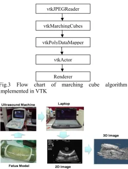
The process of surface rendering using marching cubes algorithm is follow the pipeline of function vtkJPEGReader, vtkMarchingCubes, vtkPolyDataMapper, vtkActor and renderer. vtkMarchingCubes is used to extract the iso surface of the volume based on the identical intensity of each images. It will also generate many triangles of iso surface. vtkPolyDataMapper is used to generate the mapping to rendering from poly data while vtkActor is used as an entity for rendering purpose.
Figure 3 shows the flow chart of the marching cube algorithm implemented in VTK and Figure 4 shows the block diagram of the experiment setup.
Fig.3 Flow chart of marching cube algorithm implemented in VTK
Fig.4 Block diagram of experiment setup
3 Result and Analysis
The fetus model is scanned by ultrasound machine and connects it to laptop with TV grabber. The images are stored in the laptop for 2D image processing and visualization process. The 2D image is taken using freehand with ruler as guideline for every image at constant distance of one millimeter. Several set of ultrasound image with different number of slices were taken for comparison purposes.
vtkJPEGReader
vtkMarchingCubes
vtkPolyDataMapper
vtkActor
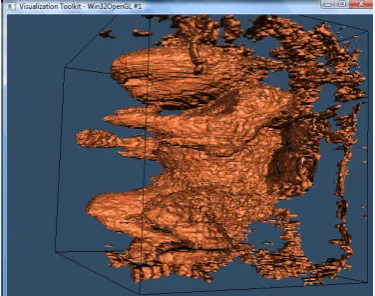
[image:3.595.311.562.267.598.2] [image:3.595.41.280.513.643.2]Figure 5 shows the result after the image processing and Figure 6 is the output of the VTK.
Fig.5 2D image processing A) Original Ultrasound image B) ROI C) Image after median filtering D) Image after contrasting E) Image after global thresholding F) Image after noise removing
[image:4.595.309.564.72.219.2]Based on the result, we can see that the 3D image of the fetal phantom is successfully reconstructed. However, the result is not smooth due to the noise unfiltered in the enhancement process. The surface of the image is also not smooth because we use the untracked free-hand system which may lead to inconsistency of scan rate and angle.
Fig.6 3D reconstruction using marching cubes algorithm
The real fetal phantom has been compared with the image reconstruct to ensure the image is matched with the real object. Figure 6 shows the correct match of head, hand and leg between 3D image and real fetal phantom.
Fig.7 Comparison between real fetal phantom and 3D fetus image
In order to generate a good 3D image, the minimum amount of slices taken need to be set and taken from the object. In this experiment, three set of images with different slices (103 slices, 155 slices and 183 slices) were taken and reconstructed. Figure 7 shows the comparison between three different amounts of slices for reconstruct 3D image. Based on the result, we can see that the 183 slices of images can produce a better look and similar image when compared to the real object.
Fig.8 Comparison between different amounts of slices for reconstruct 3D image
4 Conclusion
[image:4.595.65.258.109.311.2] [image:4.595.314.556.384.518.2] [image:4.595.67.255.479.627.2]References:
[1] H. Brinkmann, R. W. Kline, “Automated seed localisation from CT datasets of the prostate”, Med. Phys. 25:1667-1672, 1998.
[2] S. Abutaleb, “Automatic thresholding of Grey-Level Pictures Using Two-Dimensional Entropy, Computer Vision”, Graphics and Image Processing, 47:22-32, 1989
[3] Wells PNT. “Physics and engineering: milestones in medicine”. Med Eng Phys 23:147–53, 2001
[4] Yen K, Gorelick MH, “Ultrasound applications for the pediatric emergency department: a review of current literature”, Pediatr Emerg Care, 18(3): 226-34, 2002
[5] Detmer P, Bashein G, Hodges T, Beach K, Filer E, Burns D, Strandness D. “3D ultrasonic image feature localization based on magnetic scan head tracking: in vitro calibration and validation”, Ultrasound Med Biol, 20(2):923–36, 1994
[6] King D, King DJ, Shao M., “Three-dimensional spatial registration and interactive display of position and orientation of real-time ultrasound images”, J Ultrasound Med, 9(9):525–32, 1990
[7] Richard NR, Aaron F, Donal BD, Peter LM, Morris FL, and Alexander DV, “Three-Dimensional Sonographic Reconstruction: Techniques and Diagnostic Applications”, American Journal Radiology, 161 :695-702, 1993
[8] Rodolfo C, Olivia B, Fabrizio C and Davide C, “The latest in ultrasound: three-dimensional imaging”,
European Journal of Radiology Volume 27, Supplement 2, Pages S183-S187, 1998.
[9] Raichlen JS, Trivedi SS, Herman GT, St. John Sutton MG, Reichek N. “Dynamic three-dimensional reconstruction of the left ventricle from twodimensional echocardiograms”, JAm Coil Cardiol, 8:364-370, 1986
[10] Sawada H, Fujii J, Kato K, Onoe M, Kuno V. “Three dimensional reconstruction of the left ventricle from multiple cross sectional echocardiograms: value for measuring left ventricular volume”. Br Heart J 50:438-442, 1983 [11] Nikravesh PE, Skorton DJ, Chandran KB,
Attarwala YM, Pandian N Kerber RE, “Computerized three-dimensional finite element reconstruction of the left ventricle from cross-sectional echocardiograms”, Jitrason imaging, 6:48-59, 1984
[12] Levaillant JM, Rotten D, Collet Billon A, Le Guerinel Y, Rua P, “Three dimensional ultrasound imaging of the female breast and human fetus in utero: preliminary results”, Jitrason imaging ;11:149-15, 1989
[13] Wang Hongjian, P. X. “3D Medical CT Images Reconstruction based on VTK and Visual C++”,
Bioinformatics and Biomedical Engineering, 2009.
ICBBE 3rd International Conference, 2009: 1–4. [14] Babakhani Asad, DU Zhi-jiang, SUN Li-ning,
Karden Reza, Mianji A.Fereidoun, “3D Surface Reconstruction of Gray Level Ultrasonic Medical Images Based on VTK”, 2007.
[15] Hossack JA, Sumanaweera TS, Ha JS. “Quantitative 3D diagnostic ultrasound imaging using a modified transducer array and an automatted image tracking technique”, IEEE Trans Ultrason Ferroelectr Freq Control, 49(8):1029–38, 2002. [16] Richard JH, Graham MT, Andrew HG and Richard
WP, “Calibration of an orientation sensor for freehand 3D ultrasound and its use in a hybrid acquisition system”, BioMedical Engineering OnLine, 7:5, 2008
[17] A. M. Goldsmith, P. C. Pedersen, T. L. Szabo, “An Inertial-Optical Tracking System for Portable, Quantitative, 3D Ultrasound”, International Ultrasonics Symposium Proceedings, 2008.
[18] JS Duncan, N Ayache, “Medical image analysis: Progress over two decades and the challenges ahead”, IEEE Trans. On Pattern Analysis and Machine Intelligence, vol 22, no 1,pp 85-105, 2000. [19] Flemming F, Vincenzo B, Daniel AM, Keith R,
Joann M, and Barry BG, “Comparing Image Processing Techniques for Improved 3-Dimensional Ultrasound Imaging”, J Ultrasound Med 29:615-619 0278-4297, 2010.
[20] S.Sudha, G.R.Suresh and R.Sukanesh, “Speckle Noise Reduction in Ultrasound Images by Wavelet Thresholding based on Weighted Variance”,
International Journal of Computer Theory and Engineering, Vol. 1, No. 1, 1793-8201, 2009
[21] Durst, M. J., “Letters: Additional Reference to "Marching Cubes"”, Computer Graphics, 22(2):72-73, 1988
[22] Christiansen H N, Sederberg T W. “Conversion of Complex Contour Line Definitions into Polygonal Element Mosaics”, Computer Graphics,12(2), pp. 187-192, 1978
[23] A.B. Ekoule. “A triangulation algorithm from arbitrary shaped multiple planar contours”, ACM Transactions on Graphics, 10(2):182~191, 1991 [24] W.E. Lorensen,and H.E. Cline. “Marching cubes: a
high resolution 3D surface construction algorithm”,
Computer Graphics, 21(4):163~169, 1987
[25] G.M. Nielson,and B. Hamann, “The asymptotic decider:Resolving the ambiguity in marching cube”.