Numerical Study of the Plenum Chamber of a Swirling Fluidized Bed
Safiah Othman1,*, Abas A. Wahab1, Vijay R. Raghavan2
1
Universiti Tun Hussein Onn Malaysia, 86400 Parit Raja, Johor.
2
Universiti Teknologi Petronas, 31750 Tronoh, Perak.
*E-mail: [email protected]
Abstract:
A numerical investigation of the complex flow dynamics in the three-inlet plenum chamber of a swirling fluidized bed is presented. The study focuses on the influence of different geometries of flow modifying center-bodies in the plenum on the flow uniformity and plenum pressure drop, so as to arrive at an optimum choice of the hub. Flow uniformity is assessed from the standard deviation of the velocities at the exit plane of the plenum. Ten different hub geometries, in the shape of cylinder, cone, conical frustum or a combination of these are considered in the study. From the simulation results it is seen that, from the point of view of pressure drop, the best hub geometry is the full-length cylinder. For flow uniformity, the best results are got for a half-length inverted conical hub.
Keywords: Swirling fluidized bed; Choice of hub; Uniformity of flow; Numerical simulation
1.Introduction
A great many industrial processes involve contact and interaction between solids and fluids (i.e. gases or liquids). Examples include combustion, gasification of solid fuels, shales or solid wastes, drying of particles, calcining, particle heating, regenerative heat exchange, oxidation or reduction of ores, metal surface treatment and catalytic and thermal cracking [1-2]. A common way to perform such processes is through fluidization.
The swirling fluidized bed is an outcome of studies carried out in order to
overcome the disadvantages of the
conventional fluidized beds [3-4]. The system featuring the inclined injection of gas through the distributor blades is investigated in the present work. The distributor is made of a number of blades that are truncated sectors of a circle. The blades are arranged at an angle to the horizontal.
The section of a fluidized bed below the distributor plate is called the plenum chamber. This section plays a vital role in
distributing the fluid before it enters the distributor. The quality of distribution affects the performance of the fluidized bed [5-6]. Because of some interesting findings that will be further discussed in the next section, the plenum chamber is now likely to attract more interest; thus, a revival in research on the plenum of the fluidization unit is due.
2.Methodology
Based on results in [7], a detailed numerical study of the complex flow dynamics in the three-inlet plenum chamber of a swirling fluidized bed as demonstrated in Fig. 1 was carried out. The tangential inlet pipes were of equal dimensions and arranged at constant angular distance around the
chamber periphery. Two orthogonal
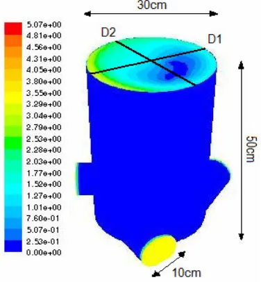
[image:2.612.104.292.317.520.2]diameters D1 and D2 were chosen to represent the velocity profile at the exit plane of the plenum chamber. The CFD code FLUENT had been used to analyze the flow model.
Fig. 1: Air volume domain showing two orthogonal diameters D1 and D2. Velocity
contour at the exit plane is exhibited.
Simulations were performed using the
finite volume method. Steady-state
segregated implicit solver and Reynolds-Averaged Navier-Stokes (RANS) Equations Models, RNG κ-ε model with standard wall treatment were applied to simulate the turbulence flow in the chamber. A standard discretisation scheme was used for the continuity equation while a first-order upwind scheme was used for both the turbulence kinetic energy equation and the
turbulence dissipation rate equation. To reduce numerical diffusion, a second-order upwind scheme was selected for the discretisation of the momentum equations. The SIMPLE algorithm was then applied to
solve the pressure-velocity coupling
algorithms.
2.1 Governing Equations
For the simulation purpose, the following 3-D equations in cylindrical
coordinate form have been solved
numerically for a Newtonian, incompressible fluid: Continuity Equation 0 1 ) ( 1 = ∂ ∂ + ∂ ∂ + ∂ ∂ z V V r r rV r z r θ θ (1)
Conservation of Momentum Equations
= ∂ ∂ + − ∂ ∂ + ∂ ∂ Z V V r V V r V r V
Vr r r z r
2 θ θ θ
[ ]
∂ ∂ + ∂ ∂ − ∂ ∂ + ∂ ∂ ∂ ∂ + ∂ ∂ − 2 2 2 2 2 2 2 1 1 1 Z V V r V r rV r r rP r r
r
r θ θ
ν ρ θ (2) = ∂ ∂ + + ∂ ∂ + ∂ ∂ z z r
r V V
r V V V r V r V
V θ θ θ θ θ
θ
[ ]
∂ ∂ + ∂ ∂ − ∂ ∂ + ∂ ∂ ∂ ∂ + ∂ ∂ − 2 2 2 2 2 2 2 1 1 1 Z V V r V r rV r r rP r r
r
r θ θ
ν ρ θ (3) = ∂ ∂ + ∂ ∂ + ∂ ∂ Z V V V r V V
V z z z
r z r θ θ ∂ ∂ ∂ ∂ + ∂ ∂ − r V r r r Z
P 1 z
1
ν
ρ
∂ ∂ + ∂ ∂ + 2 2 2 2 2 1 Z V V r z z
θ (4)
2.2 Boundary Conditions
[image:2.612.323.526.327.564.2]3.Results and Discussions
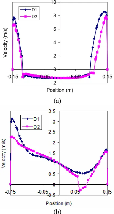
Citing from [7], Fig. 2 (a) yields highly non-uniform velocity profile at the plenum exit when applying a single tangential air inlet into the plenum. High peak in velocity occurs near the circumference of the chamber. Unwanted backflow (negative velocity) appears in a wide region at the center.
Introducing three tangential inlets into
the chamber has been proved to
accommodate more uniformity [7] as presented in Fig. 2 (b). The backflow also has been greatly reduced.
-2 0 2 4 6 8 10
-0.15 -0.05 0.05 0.15
Position (m)
V
e
lo
c
it
y
(
m
/s
)
D1
D2
(a)
[image:3.612.103.291.270.622.2](b)
Fig. 2: Velocity on D1 and D2 on the outlet plane (a) single inlet (b) three inlets.
3.1 Hub Designs
Implanting a hub at the center of the plenum chamber certainly is a great idea due to the annular blade shape of the distributor.
This is to reduce or avoid airflow in plenum center where there is no distributor air gap as well as to eliminate the air backflow in that region.
Previous study [7] has proved that the introduction of a full-length cylindrical hub in the center of the three-inlet plenum yields good uniformity in the velocity profile at the distributor along the radial and tangential direction as well as low total pressure drop.
In the present work, further
simulations were carried out considering 10 different geometries of flow modifying center-bodies in the plenum (including the cylindrical hub mentioned above) to arrive at an optimum design for the plenum chamber. The models stick to three tangential air inlets into the chamber.
Fig. 3 shows the three air inlets into the 30 cm diameter plenum chamber with a 20 cm diameter cylindrical hub at the center. The configuration is chosen so that the hub will cover the entire inner diameter of the annular blades, where there is no air gap. This hub design is modeled as model a in Fig. 4. It also shows 9 other hub designs for the same 3-inlets chamber with the same dimensions as model a.
[image:3.612.360.486.446.616.2][image:4.612.330.529.79.223.2]
(b)
Fig. 3: Three-inlets chamber with a full-length cylindrical hub at the center (a)
isometric view (b) plane view.
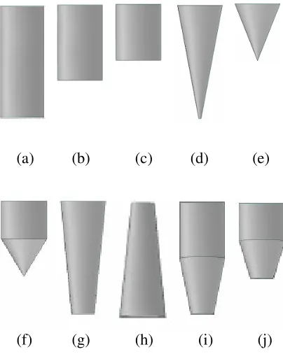
(a) (b) (c) (d) (e)
[image:4.612.133.252.80.207.2](f) (g) (h) (i) (j)
Fig. 4: Various hub designs (model a-i).
3.1.1 Pressure Drop
The total pressure drop across the chamber for each model as extracted from the numerical results is tabulated in the following Table 1.
Table 1. The total pressure drops in the plenum chamber for various hub designs.
Model Length Type
Pressure Drop (Pa)
a Full cylinder 6.57
b 2/3 cylinder 7.76
c 1/2 cylinder 8.61
d Full cone 8.34
e 1/2 cone 9.3
f 1/3 cylinder, 1/3 cone 8.89
g Full Inverted frustum 7.84
h Full Upright frustum 10.25
i 1/2 cylinder, 1/2 frustum 6.91 j 1/3 cylinder, 1/3 frustum 7.97
From the point of view of pressure drop, the best hub geometry is the full-length cylinder.
3.1.2 Statistical Analysis
A statistical analysis was conducted in order to provide additional criteria in deciding the geometry of hub to be chosen. The standard deviation of velocity magnitude at the exit plane of the plenum chamber for 10 models was demonstrated in the Table 2.
Low standard deviation yields high
[image:4.612.96.298.257.510.2]uniformity.
Table 2. The standard deviation for velocity on the exit plane of the plenum chamber.
Model Length Type
Standard Deviation
(m/s)
a Full cylinder 1.2
b 2/3 cylinder 1.198
c 1/2 cylinder 1.134
d Full cone 1.197
e 1/2 cone 1.018
f 1/3 cylinder, 1/3 cone 1.041
g Full Inverted frustum 1.113
h Full Upright frustum 1.766
i 1/2 cylinder, 1/2 frustum 1.118 j 1/3 cylinder, 1/3 frustum 1.123
For flow uniformity (low in standard deviation), the best results are got for a half-length inverted conical hub.
[image:4.612.328.528.442.645.2] [image:4.612.331.529.442.644.2]velocity at the outer plane, the model i with a 1/2 cylinder-1/2 frustum hub in the center of the three-inlets plenum is chosen for further consideration. This design provides low pressure drop as well as low standard deviation of velocity which implies high uniformity.
3.2 Multiple inlets
Although three-inlet plenum has been shown in [7] to accommodate the desired characteristics, more simulations were conducted for 2 and 4 inlets to investigate if the pattern is still relevant for the chosen hub.
-2 -1 0 1 2 3 4 5 6
-0.15 -0.05 0.05 0.15
Position (m)
V
e
lo
c
it
y
(
m
/s
)
D1 D2
(a)
0 0.5 1 1.5 2 2.5 3 3.5
-0.15 -0.05 0.05 0.15
Position (m)
V
e
lo
c
it
y
(
m
/s
)
D1 D2
(b)
0 0.5 1 1.5 2 2.5 3 3.5 4
-0.15 -0.05 0.05 0.15
Position (m)
V
e
lo
c
it
y
(
m
/s
)
D1 D2
[image:5.612.345.510.85.254.2](c)
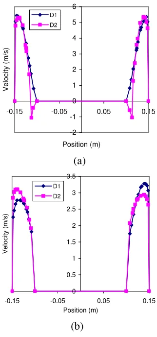
Fig. 3: Velocity profile on the outlet plane of the plenum with hub design as in model i (a)
2 air inlets (b) 3 air inlets (c) 4 air inlets.
Fig. 4(a-c) presents the velocity profile on the chamber outlet plane for 2, 3 and 4 tangential air inlets. The design was based on the compromise between desired performance characteristic and the unit simplicity. As model with 4 air inlets did not yield much improvement, 3-inlets model i remains the optimum design chosen.
4. Conclusion
[image:5.612.117.278.266.610.2]provides low pressure drop as well as low standard deviation of velocity which implies high uniformity.
Nomenclature
P pressure
ρ density
ν kinematics viscosity
r,θ,z cylindrical polar coordinates
V velocity
Vr,Vθ,VZ component of velocity vector
References
[1] W. Seenadera, B.R. Bhandari, G. Young and B. Wijesinghe, Methods for effective fluidization of particulate food materials, Dry. Technol. 18 (7) (2000) 1537-1557.
[2] C. K. Gupta, D. Sathiyamoorthy, Fluid bed technology in materials processing, CRC Press LLC, Boca Raton, 1999.
[3] B. Sreenivasan and V. R. Raghavan,
Hydrodynamics of a swirling fluidized bed, Chemical Engineering and Processing 42 (2002) 99-106.
[4] M. Ozbey, M.S. Soylemez, effect of swirling flow on fluidized bed drying of wheat grains, Energy Conversion & Management, 46 (2005) 1495-1512.
[5] E. Peirano, V. Delloume, F. Johnsson, B.
Leckner and O. Simonin, Numerical
simulation of the fluid dynamics of a freely bubbling fluidized bed: influence of the air supply system, Powder Technol. 122 (1) (2002) 69-82.
[6] F. Johnsson, G. Larsson and B, Leckner, Pressure and flow fluctuations in a fluidized bed−interaction with the air-feed system, Chem. Eng. Sci. 57 (8) (2002) 1379-1392.
[7] S. Othman and V. R. Raghavan, Design of the plenum chamber of a swirling fluid bed
by means of numerical simulation,