Procedia Engineering 53 ( 2013 ) 271 – 277
1877-7058 © 2013 The Authors. Published by Elsevier Ltd.
Selection and peer-review under responsibility of the Research Management & Innovation Centre, Universiti Malaysia Perlis doi: 10.1016/j.proeng.2013.02.036
Malaysian Technical Universities Conference on Engineering & Technology 2012, MUCET 2012
Part 1 - Electronic and Electrical Engineering
Dual Frequency X-Band Reflect array Antenna using Dual Gap
N. H. Sulaiman
a,* and M. Y. Ismail
aaWireless and Radio Science Center (WARAS) Universiti Tun Hussein Onn Malaysia
86400 Parit Raja, Johor, Malaysia
Abstract
The demand for low cost and less weight antenna with compact broadband features in communication system is rapidly increasing. In this work, the possibility of employing dual gap on reflectarray patch element for static phase rangeperformancewith enhanced dual frequency operation of reflectarray antenna are presented. By introducing dual gap on rectangular patch element, the static phase range is shown to be significantly increased for dual frequency operation from 294.40° to 343.50°. Moreover, 49.1° enhancement in static phase range offers a reduction in the phase error produced by the limited static phase range of 4.58% demonstrated. Additionally, a novel formulation of dual frequency reflectarray antenna based on Finite Integral Method (FIM) has also been developed. The comparison between simulated and measured results is also presented in this work. Several parameters of reflectarray antenna such as bandwidth performance and static phase range are discussed in this paper.
© 2013 The Authors. Published by Elsevier Ltd.
Selection and/or peer-review under responsibility of the Research Management & Innovation Centre, Universiti Malaysia Perlis.
Keywords: dual gap; dual frequency reflectarray antenna; static phase range; phase errors.
1.Introduction
The reflectarray is a combination of a flat reflector and array of microstrip patch elements printed on a thin dielectric substrate. Printed reflectarrayantennascombine certain significant advantages of reflector antennas and phased array antennas due to less weight, less complexity, low cost and flat structure which is easily mounted on the top surface [1]-[3]. The use of the printed reflectarray antenna technology with significant innovative features allows possible solutions for mobile ground station antennas which is able to satisfy not only the radiation requirements but also reduced volume with ease of deployments [4]. The compact antenna structures with broadband techniques and multiple functionalities have become more important in modern antenna designs [5].
However, reflectarray antenna has a crucial limitation of bandwidth performance due to narrow band elements and spatial phase delays. In the reflectarray antenna design, the phase range should be 360° at a given frequency in order to produce a suitable compensation for planar wave front. To overcome this limitation, high static phase range with less phase error is required to obtain a uniform phase distribution. Due to theselimitations, many researchers have proposed various techniques for dual frequency operation to optimize the reflectarray antenna performance [6].The complexityof antenna
* Corresponding author. E-mail address: noor_hafizah86@yahoo.com
© 2013 The Authors. Published by Elsevier Ltd.
systems configurations on the communication towers can be avoided by introducing dual frequency antenna using single element. With dual frequency operation, the size and cost of antenna can be reduced. Other than that, dual frequency antenna is suitable for several systems such as satellites and global position systems (GPS) which are required to operate at two different frequencies apart from each other [7]. Variety of methods has been introduced to obtain dual frequency operation such as using slots in the patch [8], [9]. Another previous work shows dual frequency operation by using three pairs of thin slits from the sides of a rectangular patch and feeding with a microstrip feedline [10].Dual frequency operation also can be obtained by integrating rectangular patch using RF MEMS switches [11]. However, it can be observed that the dual frequency can be obtained by using additional devices which increases the design complexity of the system. In order to overcome these limitations, a simple technique to obtain dual frequency is required to be developed.
In this work, a dual frequency reflectarray antennausing dual gap configuration on rectangular patch element is presented. The introduction of dual gap has been proposed to be integrated with rectangular patch element in order to investigate the feasibility of realizing dual frequency reflectarray operation with enhanced static phase range performance with less phase errors.Moreover, a novel formulation of dual frequency based upon dual gap on rectangular patch antenna has been introduced in this work. Various samples of fabricated dual gap on the rectangular patch element are presented in order to examine the feasibility of dual frequency operation in the X-band frequency range.Comparison of simulated and measured scattering parameter is providedby using waveguide simulator technique.
2.Design and Methodology
In this section, rectangular patch element has been designed using Rogers RT/d 5880 as a dielectric substrate. Commercially available CST computer model has been used to design a unit cell element with proper infinite boundary conditions. Rectangular patch reflectarray antenna was constructed on a 0.787 mm thick dielectric substrate with patch element dimensionsLp=10.0 mm x Wp=11.5 mm. In order to investigate the possibility of realizing dual frequency antenna,
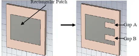
dual gap configurations has been introduced on a rectangular patch element as shown in Fig. 1.
[image:2.544.165.395.332.426.2]
Fig. 1. Model design in CST MWS (a) Rectangular patch element without dual gap and (b) Rectangular patch element with dual gap
Fig. 2. Detail dual gap configuration on the rectangular patch element
Fig. 1 shows the model of a rectangular patch element without dual gap and with dual gap designed by using commercial computer model of CST MWS. The details of introduction of dual gap on the rectangular patch are shown in Fig. 2. In this work, gap A and gap B as shown in Fig. 2 have the same dimensions of Wg= 2.00 mm xLg = 1.00 mm. In
order to observe the effect of the introduction of dual gap configuration, the model design has been simulated in the X-band frequency range. The width, Wg of the gap is varied from 2.00 mm to 3.20 mm while the length, Lg of the dual gap is kept
constant at 1.00 mm. From the dual gap performance, the formulation of dual frequency has been derived which considers the frequency for a particular width of dual gap obtained by using the formula as shown in Equation (1).
Wp
A
B Lp
A=B
Wg
Lg
Gap A
[image:2.544.169.379.458.561.2](1)
Where,
fd is desired frequency for the specific frequency of dual gap
fs is secondary frequency
fp is the primary frequency
is the interval of the width variation
In order to verify the validity of this formula, computer programming software of Turbo C++ has been used and a set of results from different widths of dual gap has been generated. The feasibility of dual frequency operation has been demonstrated by employing dual gap on the rectangular patch element. In order to show the dual frequency operation in X-band frequency range, variable width of dual gap has been generated from 2.80 mm to 3.20 mm.
[image:3.544.169.351.302.427.2]The variation of dual frequency with different width of dual gaps is shown in Fig. 3. It is shown that by varyingwidth of the dual gap on rectangular patch element from 2.80mm to 3.20mm, variation of dual frequency can be obtained. It can be seen that the gap with the width, wg=3.20mm offers -0.98dB reflection loss at 8.31 GHz while the second resonant frequency at 11.98 GHz offers 2.05dB of reflection loss. The reason behind the difference of loss performance isdue to the modification of the surface current and electric field distributions on the surface of patch element and substrate region respectively. It has been demonstrated that by using different widths of dual gap, dual frequencies have been obtainedin whichdual frequency can be easily adjusted by changing the width of dual gap.
Fig. 3. Dual frequency using variable width of dual gap, wg
3. Fabrication Measurement Setup
3.1 Fabrication Samples
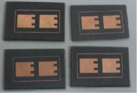
In order to validate the feasibility of dual frequency operation obtained from simulations, various samples of dual gap embedded on the rectangular patch antenna has been printed on Roger 5880 dielectric material. The fabricated samples are shown in Fig. 4.
Fig. 4. Fabricated samples of dual gap on the rectamgular patch element
s p
d s
s p
f
f
f
w
f
[image:3.544.202.343.529.625.2]Fig. 4 shows the fabricated sample oftwo identical size patch element unit cell reflectarray. The fabrication of this sample has been prepared by using photolithography process. For each design, two patch element of identical size are fabricated where the element spacing d is kept at half wavelength to reduce mutual coupling effects. The scattering parameters measurements of the designed samples have been carried out by using vector network analyzer with waveguide simulator technique [12].
3.2 Measurement Setup
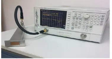
[image:4.544.176.365.191.291.2]Scattering parameter measurement was carried out using network analyzer. By connecting waveguide simulator to the vector network analyzer via coaxial cable and waveguide adapter, scattering behavior such as reflection loss and reflection phase can be obtained. The complete connection setup is shown in Fig. 5.
Fig. 5. Measurement setup for scattering parameters measurements
As depicted in Fig. 5, two patch elements are inserted into the aperture of waveguide simulator. The investigations for dual gap reflectarray element have been carried out to analyze the performance of reflectarray antenna. Reflection phase, reflection loss and phase errors have been characterized in order to analyze the scattering parameter behaviour of reflectarray elements.
3.3 Reflection Phase and Figure of Merit (FoM)
In order to analyze the bandwidth performance of rectangular patch without and with dual gap, Figure of Merit (FoM) can be calculated from the reflection phase curve. The Figure of Merit (FoM) can be defined as the ratio of the change in the reflection phase to the change in the frequency (static phase range) [12] which indicates an aspect of performance for the bandwidth and is given by;
0
( / )
FoM MHz
f
(2) Where
is the change in the reflection phase in degrees
fis the change in the resonant frequency in MHz of the reflectarray antenna and FoM is calculated in °/MHz.
3.4 Reflection Loss and Bandwidth
The reflection loss curve is considered as an important parameter in the analysis of the reflectarray design. The bandwidth of a reflectarray can also be represented by the reflection loss curves. In order to analyze the bandwidth performance, the ratio of bandwidth is defined by moving 10% and 20% above the reflection loss values [13].
3.5 Phase Error
4. Results and Analysis
This section provides the details of scattering measurements and comparison between the simulated and measured results. The waveguide has been used in order to represent an infinite reflectarray antenna using a two patch element unit cell.
4.1 Reflection Loss
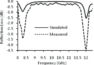
The comparison between simulated and measured reflection losses for width of dual of 3.20mm gap is plotted in Fig. 6. Dual resonant frequency measured result has shown a good agreement with simulated results obtained from CST MWS. However, it can be observed that there is a discrepancy between simulated and measured results. The summary of reflection loss results is shown in Table 1.
[image:5.544.187.352.208.322.2]Fig. 6. Simulated and measured reflection loss curve
Table 1. Comparison of Reflection Loss Between Simulated and Measured Result
Result
Resonance 1 Resonance 2
Frequency
(GHz) ReflectionLoss (dB) Frequency (GHz) Reflection Loss (dB)
Simulated 8.31 -0.99 11.98 -1.52
Measured 8.38 -3.45 12.02 -4.46
As depicted in Table 1, it can be observed that the first simulated resonant frequency of 8.31 GHz offers -0.99 dB of reflection loss as compared to measured result which has resonantfrequency of 8.38 GHz with -0.345 dB of reflection loss. A discrepancy of 70MHz has been observed in resonant frequency while the measured reflection loss differs by 2.45dB as compared to the simulated results. It has also beendemonstrated that the second simulated resonant frequency of11.98 GHz with -1.52 dB of reflection loss has a close agreement with the measured result which has resonant frequency of 12.02 GHz with -2.94 dB of reflection loss.
The discrepancy of reflection loss between simulation and measurement is due to the connections and fabrication errors during fabrication process. In order to investigate the difference in reflection loss between simulations and measurements, a thorough investigation has been carried out on the fabricated samples. By using surface profiler, the surface of dual gap on the rectangular patch element has been observed.
(a)
(b)
Fig. 7. (a) Fabricated samples (b) Close up view of the fabricated samples using surface profiler
4.2 Reflection Phase
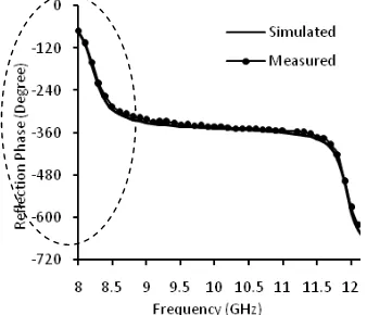
[image:6.544.100.298.64.210.2]In order to represent the bandwidth performance, reflection phase curve is plotted in Fig.8. As depicted in Fig.8, the comparison of simulated and measured reflection phase curve is shown. From the reflection phase curve, static phase range and figure of merit have been analyzed. It can be observed that the measured results have a good agreement with the simulated results. It has also been shown that by introducing dual gap on the rectangular patch element dual frequency operation can be achieved with the highest static phase range performances of 343.5°. The summaryof result obtained from reflection phase curve has been summarized in Table 2.
Fig. 8. Simulated and measured reflection phase curve
Table 2. The Reflection of Phase Curve of Dual Frequency Operation
Result
Resonance 1 Resonance 2
Static Phase Range (0)
Figure of Merit , FoM
(0/MHz)
Static Phase Range (0)
Figure of Merit , FoM
(0/MHz)
Simulated 294.40 0.269 343.5 0.284
[image:6.544.175.344.337.482.2]Table 2 shows the static phase range and figure of merit for dual frequency operation. As depicted in Table II, it can be observed that the simulated result for first resonant frequency offerFoM of 0.269°/MHz with 294.40° of static phase range as compared to measured results which provides a figure of merit of 0.264°/MHz with 285.10° of static phase range. It can be seen that discrepancy between simulated and measured results is 9.3° for the first resonancefrequency and 4.1° for the second resonance of. The difference between simulated and measured results for static phase range and FoM is due to the connection and fabrication errors.
5. Conclusion
It can be concluded that by introducing dual gap on the rectangular patch, reflectarray antenna offers significant advantages for dual frequency application that can be used for X- band applications. An increase in the static phase range with decrease in phase error performance is demonstrated due to the introduction of dual gap on the rectangular patch element. The comparison between simulated and measured results shows a good agreement. It has also been shown that the performance of reflectarray antennas in term of bandwidth and static phase range can be improved by introducing dual frequency operation. Moreover, a novel and simple configuration to obtain dual frequency operation has been presented which can be applied for dual frequency antenna applications such as Global Positioning Systems (GPS) and Synthetic Aperture Radar (SAR).
Acknowledgment
We would like to thank the staff of Wireless and Radio Science Centre (WARAS) of Universiti Tun Hussein Onn Malaysia (UTHM) for the technical support.
References
[1] J.Huang and J.A. Encinar,Reflectarray Antennas, Wiley, InterScience, 2007. [2]
Antennas and Propagation Magazine, Vol. 47, No. 2, pp. 13-29, 2005.
[3] -layer printed reflectarrays using patches of variable
-1410, 2001.
[4] aterial
4, No.1. pp 28-35, 2010.
[5] l. 2, pp.
1134-1137,1998. [6]
Antennas Propagation., Vol. 150, No.6, pp. 440 444, 2003.
[7] -943, Sept. 1984.
[8] Antenna Propag., Vol.
142, pp. 225-232, Jun 1995.
[9] ostrip antenna and its application to a two element dual frequency
-361, 1999.
[10] N. Misran, M.T. Islam, N. M. Yusop
u-Confernce on Electrical Engineering and Infromatics, Vol. 2, pp. 699-702, August, 2009.
[11] lectronic
Letter, Vol. 44, pp. 76-77, No. 2, 2008.
[12]
-and Optical Technology Letters, Vol. 53, pp. 77-80, January 2011.
[13] gurable
reflectarray antenna with slots embedded patch -4, 2010.
[14] nas and