© 2016, IRJET ISO 9001:2008 Certified Journal Page 636
HYBRID REINFORCEMENT DEVELOPED BY USING CFRP SHEET
K.NANDHINI
1,Mr.S.SIVA RAMAKRISHNAN, M.E.,[Ph.D.]
21
ME structural Engg Dept, Agni college of Technology, Chennai
2
Assistant Professor, Civil dept, Agni college of Technology, Chennai
---***---Abstract -
The conventional steel reinforcement replacement with CFRP sheet wrapping bars has been investigated to overcome the corrosion problem in bridge decks, marine structures and chemical plants. In addition to their excellent non-corrosive characteristics, Hybrid Reinforcements System (HRS) has high strength to weight ratio, good fatigue properties and brittle resistance. The present project work aims to study the effect of Hybrid reinforcement developed by wrapping CFRP sheet on steel rod as core material was used as tensile reinforcement in reinforced concrete beam. Eight beams, including four control beams reinforced with steel, were tested for strength, deflection, ultimate load, and failure characteristics. It was revealed that the use of the Hybrid Reinforcement resulted in remarkable increases in mainly beam ultimate load capacity as well as corrosion resistance.Key Words: CFRP; Hybrid reinforcements; Beams; Strain; Corrosion; Flexural strength.
1.
INTRODUCTION
Corrosion of reinforcement is a major problem facing infrastructure in all structures. Particularly in bridge deck, marine structures, wastewater treatment facilities, chemical plants and deicing salts. Many structures in adverse environments have experienced unacceptable damages and life time reduced and affect serviceability of structural members due to the corrosion of reinforcing steel. The need for corrosion resistant in structure and rehabilitation in bar corroded structures has led to determine the alternative for steel. Because they are mostly using glass fiber reinforced polymers (GFRP) bars in strengthening and rehabilitation of RC flexural members in all construction applications. It has some important properties are high electrical insulating, heat resistance, and lowest cost. The use of GFRP Rod to strengthen the structural members started with the external
bonding and this technique became popular all over the world. But GFRP bar are having disadvantage is brittle collapse, limited experience and low modulus of elasticity. To address this problem, we propose to introduce a new bar with ductile nature. Emad El-SayedEtman, et.al. (2011), “Innovative Hybrid Reinforcement for Flexural Members” [1].
(CFRP) sheet wrapping on steel rod as core material used to making Hybrid Reinforcement developed. Carbon fibers are having some properties, high tensile strength and elastic modulus. HRS is simply defining an innovative reinforcing material for corrosion resistance of marine structural elements. This reinforcement are mainly used as alterative reinforcement of structural members, due to some advantages such as resistance to corrosion under deicing salts. The HRS used in this project consists of mainly two parameters are core reinforcement and perimeter reinforcement. The core reinforcement which is made of (TMT) bars was covered with epoxy and while wet surrounded by perimeter one layers of fiber reinforcement
(carbon fibers).Structural members using HRS
reinforcement in external (or) internal reinforcement. In this project, they are using internal reinforcement in HRS. G. Nossoni et.al. (2014), “Rate of Reinforcement Corrosion and Stress Concentration in Concrete Columns Repair with Bonded and Un bonded FRP Wraps” [14]. This project presents tests on flexural members 4 (RC beam) reinforced with HRS, as their main reinforcement, to achieve the high strength and corrosion reduce in these beams. HRS is used to design the various material of reinforcing components to act perfectly single reinforcement system. The HRS mainly consists more variables in the project were the type core reinforcement and number of layer used in perimeter reinforcement. The present project results expected that the HRS reinforcements can increase the strength, ultimate load, deflection at ultimate load, strains and reduce corrosion.
2.
EXPERIMENTAL PROGRAM
2.1. Materials used
2.1.1. Aggregates and cement
© 2016, IRJET ISO 9001:2008 Certified Journal Page 637 for Coarse and Fine aggregates from natural sources for
concrete” [18]. Fine Aggregate, Coarse Aggregate having a specific gravity 2.6 and 2.8. A maximum size of 20mm is used as coarse aggregate in concrete.
2.1.2 Water
Water is a mainly important ingredient of concrete and chemical reaction with cement. Clean potable water conforming to IS 456-2000 [16] was used.
2.1.3 Steel bar
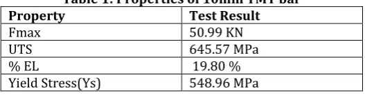
[image:2.595.30.294.304.373.2]The longitudinal reinforcements used were high-yield strength deformed bars of 10 mm diameter. The stirrups were made from TMT bars with 8 mm diameter. This bar are used to making control beams and hybrid beams.
Table 1: Properties of 10mm TMT bar Property Test Result
Fmax 50.99 KN
UTS 645.57 MPa
% EL 19.80 %
Yield Stress(Ys) 548.96 MPa
2.1.4 Hybrid Reinforcement
[image:2.595.48.278.497.546.2]The Hybrid Reinforcement System (HRS) simply define as innovative reinforcing material of structural element and it consists more than one reinforcing material. Hybrid Reinforcement developed by using wrapped CFRP sheet on (TMT bar) used as core material CFRP sheet used in this project as one layer of perimeter. It have a high yield stress, ultimate tensile strength (UTS) and elongation compared to TMT bar.2.1 Aggregates and Cement
Fig 1. Samples of hybrid reinforcing bars
2.1.5 Silicon Carbide
Chemical compound of carbon and silicon is simply say silicon carbide. Silicon carbide is an excellent abrasive and has been produced and made into grinding wheels and other abrasive products.
2.1.6 CFRP Sheet
Mainly used in retrofit and repair structurally deficient infrastructures such as pre stressed concrete bridge girder and aerospace industry are popularly used because its strength to weight ratio is highest among all FRPs. CFRP Sheet wrapping used in masonry columns of rehabilitation due corrosion control, earthquake resistant structures.
Properties
alkali resistant
low thermal conductivity
non-magnetic
high fatigue resistance high ultimate strain resistant to corrosion
2.1.7Matrix Materials
Fibers are cannot directly transmit loads from one to another.Bind the fibers together, transfer loads to the fibers, and damage due to handling by using matrix material. In this project are using epoxy resin and hardener. Various types of resin are there, but using Araldite MY753. Because they have many advantages are medium viscosity, corrosion resistance, mechanical and thermal properties are good, and electrical properties.
Advantages
very good gap-filling good wetting chemical resistance much longer life
Table 2: Properties of epoxy resin Property Test Result
Viscosity at 25° C µ(cp) 12000
Density ρ (g.cm-3 ) 1.16
2.1.6 Strain Gauge
A strain gauge is constructed by bonding a fine electric resistance wire or photographically etched metallic resistance foil to an electrical insulation base using appropriate bonding materials, and attaching gauge leads. They can measure the gauge parallel to the surface in which direction we want to measure the strains.
2.2. MIX DESIGN
The concrete mix has been designed for M25grade
as per IS code. IS: 10262:2009 “concrete mix proportioning”,
Bureau of Indian Standards, New Delhi[17].The specified concrete grade involves the economical selection of relative proportions of cement, fine aggregate, coarse aggregate and water.
Table 3:Mix Proportion for M25 Grade
Constituent Cement Fine
Aggregate Coarse aggregate Water
Weight/
Volume 425.73 kg/m3
645.5
kg/m3
1183.6
kg/m3
191.58 lit
© 2016, IRJET ISO 9001:2008 Certified Journal Page 638 2.3. SPECIMEN DETAILS
[image:3.595.307.560.186.296.2]The present project test for 8 RC beams. All tested beams had 130-mm width, 230-mm depth and 1,400-mm length. The hybrid reinforced beams were reinforced with two numbers of 10mm hybrid reinforced bars at the bottom, and two numbers of 10 mm diameter TMT bars at the top, with the 8 mm diameter stirrups at various spacing 150 mm and 300 mm centre to centre spacing. The dimensions and details of supports common to all beams. For the four control beam, the reinforcement includes only TMT steel bars. And the four hybrid reinforcement includes two components .The reinforcement details are shown in fig.3. Three types of wrapping length in Hybrid reinforcement bar were used in total beams are described below table 1.The five strain gauges are used to measure the strains tin this project. A three strain gauge was attached to an HRS bar of the main reinforcement at the mid span and others are at 200mm spacing from the mid span of tension surface at the reinforcement, another two strain gauge was attached to a top surface of beam and bottom surface of beam at midspan. A LVDT was also mounted to measure the deflection at midspan of beam.
Fig 2: longitudinal profile and cross section
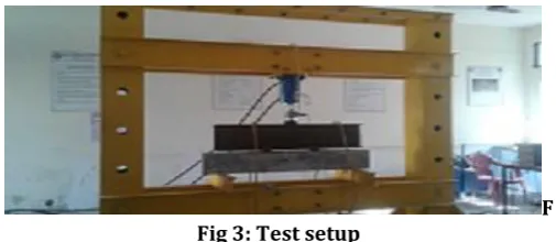
2.4. TEST ARRANGEMENT
The beams were tested in the Loading frame 40 Tons in capacity and test setup are show in fig 3. All beams were tested up to ultimate load, under two-point loading over a simply supported. And also used load cell on the top of beam.A concentrated load apply on a stiff steel distributor beam by displacement control was used to drive hydraulic jack, which then produces two-line loads on the beam. To measure the deflections, LVTD were placed at the centre of the beam at bottom. The load was applied in 1ton
incrementally up to yield point of the beam reinforcement. The strain gauge was used for recording the strains on beam.Then the beam was tested to failure by applying the load in increments, and clearly observe all reading, such as first crack load, ultimate load, deflection and strain.
F Fig 3: Test setup
3.
TEST RESULTS AND DISCUSSIONS
3.1. Mechanical properties
The average compressive strength and tensile strength at 28 days is 25 N/mm2, 2.3 N/mm2 .
3.2 First crack and ultimate load
[image:3.595.35.296.377.608.2]© 2016, IRJET ISO 9001:2008 Certified Journal Page 639 15.9
14.2
10.6
11.3 11.7 14.1
17.9 19.1
0 5 10 15 20 25
1 2 3 4 5 6 7 8
Deflection at Ulimate Load
[image:4.595.36.296.69.502.2]SB1 SB2 GB3 GB4 HCB5 HCB6 HCB7 HCB8
[image:4.595.37.550.381.749.2]Fig.4 Deflection at ultimate load
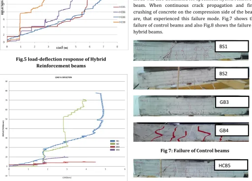
Fig.5 load-deflection response of Hybrid Reinforcement beams
-10 0 10 20 30 40 50 60 70 80 90
0 1 2 3 4 5 6
D
E
FLE
CTIO
N
(m
m
)
LOAD(tons)
LOAD Vs DEFLECTION
SB1 SB2 GB3 GB4
Fig6: load-deflection response of control
3.4 Load-deflection response
The load-deflection response of the (HCB5, HCB6, HCB7, HCB8) beams is compared with that of the control beam (SB1, SB2, GB3, GB4). Figure 5 and 6 represents the load-deflection response of the Hybrid Reinforcement beams, and control beam.
3.5 Failure modes
Various modes of failures are observed in Beams reinforced with HRS. The yielding of the core reinforcement in all beam observed after failures. In specimen hybrid beam, where the core reinforcement was made of TMT bar, failure was initially flexural. The vertical cracks that started on the tension face. In this cracks are continuously and finally a sudden failure occurred under the concentrated line load except specimen hybrid reinforcement that failed in a brittle manner. For the control specimen, a flexural failure mode was clearly observed in the form of deep flexural cracks that started on the extreme tension side of the beam. This failure mode was also dominated for specimens hybrid reinforced beam. When continuous crack propagation and final crushing of concrete on the compression side of the beam are, that experienced this failure mode. Fig.7 shows the failure of control beams and also Fig.8 shows the failure of hybrid beams.
Fig 7: Failure of Control beams
BS1
BS2
GB4
GB3
© 2016, IRJET ISO 9001:2008 Certified Journal Page 640
Fig 8: Failure of Hybrid Reinforcement beams
[image:5.595.346.581.128.479.2]Table 4: Summary of Test Result
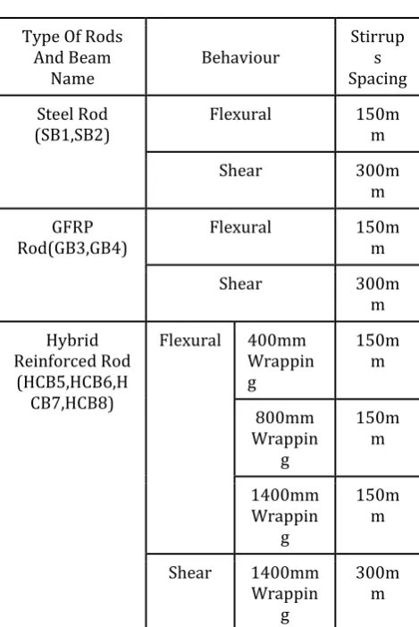
Table 5: Reinforcement Detailing
4. CONCLUSION
Based on the presented experimental work and discussions the following conclusions are
The use of carbon fibers in the perimeter layer of a HRS resulted in specimens with higher deflection and load capacity compare to control beam. The load carrying capacity of the HCB is 55%
greater than BS and 93% greater than GB.
The deflection at ultimate load of HCB is 37% greater than BS and 80% greater than GB.
Reduce the corrosion problem in Hybrid Beam because, they have high strength, deflection.
Beam ID
First crack load
[KN]
Deflection at first crack load
[mm]
Ultimate load
[KN]
Deflection at
ultimate load
[mm]
BS1 1.5 1.4 5.16 13.9
BS2 1.5 2.0 6.08 12.2
GB3 1.4 1.6 4.13 10.6
GB4 1.45 1.9 5.05 11.3
HCB5 1.49 0.8 6.03 15.8
HCB6 1.5 1.0 6.91 16.1
HCB7 1.21 1.7 7.31 17.9
HCB8 1.3 2.1 8.00 19.1
Type Of Rods And Beam
Name Behaviour
Stirrup s Spacing
Steel Rod
(SB1,SB2) Flexural 150mm
Shear 300m
m
GFRP
Rod(GB3,GB4) Flexural 150mm
Shear 300m
m
Hybrid Reinforced Rod
(HCB5,HCB6,H CB7,HCB8)
Flexural 400mm
Wrappin g
150m m
800mm Wrappin
g
150m m
1400mm Wrappin
g
150m m
Shear 1400mm
Wrappin g
300m m
HCB6
HCB7
© 2016, IRJET ISO 9001:2008 Certified Journal Page 641
REFERENCES
[1].Emad El-SayedEtman, et.al. (2011), “Innovative Hybrid Reinforcement for Flexural Members” Journal of Composites for Construction, Vol. 15, No. 1, February 1, 2011. ASCE.
[2].Khaled Soudki, et.al., (2003), “Bond Behavior of Corroded Steel Reinforcement in Concrete Wrapped with Carbon Fiber Reinforced Polymer Sheets” Journal of Materials in Civil Engineering, Vol. 15, No. 4, August 1, 2003. ASCE.
[3].MahendrakumarMadhavan et.al. (2015), “Flexural Strengthening of Structural Steel Angle Sections Using CFRP, Experimental Investigation” Journal of Composites for Construction, ASCE.
[4].ZenonAchillides, et.al., (2004), “Bond Behavior of Fiber Reinforced Polymer Bars under Direct Pullout Conditions” Journal of Composites for Construction, Vol. 8,No. 2, April 1, 2004. ASCE.
[5].Ganesh Thiagarajan, et.al. (2015), “Experimental and Analytical Behavior of Carbon Fiber-Based Rods as Flexural Reinforcement” Journal of Composites for Construction, Vol. 7, No.1, February 1, 2003. ASCE. [6].M. Harajlis, et. al., (2010) “Bond Performance of GFRP
Bars in Tension, Experimental Evaluation and
Assessment of ACI 440 Guidelines” Journal of Composites for Construction, Vol. 14, No. 6,
December 1, 2010. ASCE.
[7].D. M. Penagos-Sanchéz et.al., (2015), “Strengthening of the Net Section of Steel Elements under Tensile Loads with Bonded CFRP Strips” Journal of Composites for Construction, ASCE.
[8].Tamer El Maaddawy, et.al., (2006), “Effect of Fiber-Reinforced Polymer Wraps on Corrosion Activity and Concrete Cracking in Chloride-Contaminated Concrete Cylinders ” Journal of Composites for Construction, Vol. 10, No.2, April 1, 2006. ASCE.
[9].Vincenzo Giamundo, et.al. (2013), “Analytical Evaluation of FRP Wrapping Effectiveness in Restraining Reinforcement Bar Buckling” Journal of Structural Engineering, ASCE.
[10]. Sherif El-Tawil, Ph.D., P.E., M. et.al., (2009), “Inhibiting Steel Brace Buckling Using Carbon Fiber-Reinforced Polymers, Large-Scale Tests”, Journal of Structural Engineering, Vol. 135, No. 5, May 1, 2009. ASCE
[11]. M. M. Correia et.al. (2013), “Buckling Behavior and Failure of Hybrid Fiber-Reinforced Polymer Pultruded Short Columns” Journal of Composites for Construction, Vol. 17, No. 4, August 1, 2013. ASCE.
[12]. Kailai Deng, et.al. (2015), “Study of GFRP Steel Buckling Restraint Braces” Journal of Composites for Construction, ASCE.
[13]. Maria Antonietta Aiello, et.al., (2007), “ Bond Performances of FRP Rebars-Reinforced Concrete”
Journal of Materials in Civil Engineering, Vol. 19, No. 3, March 1, 2007. ASCE.
[14]. G. Nossoni et.al. (2014), “Rate of Reinforcement Corrosion and Stress Concentration in Concrete Columns Repair with Bonded and Un bonded FRP Wraps” Journal of Composites for Construction, ASCE. [15]. EkinEkiz, A.M. et.al. (2008), “Restraining Steel Brace
Buckling Using a Carbon Fiber-Reinforced Polymer Composite System, Experiments and Computational Simulation” Journal of Composites for Construction, Vol. 12, No. 5, October 1, 2008.
[16]. IS: 456:2000 “Code of practice for plain and reinforcement concrete”, Bureau of Indian Standards, New Delhi.
[17]. IS: 10262:2009 “concrete mix proportioning”, Bureau of Indian Standards, New Delhi.
[18]. IS: 383:1970 “Specification for coarse and fine aggregate from source for concrete” Bureau of Indian Standards, New Delhi.