© 2016, IRJET | Impact Factor value: 4.45 | ISO 9001:2008 Certified Journal
| Page 255
Topography Optimization of the Inner Panel of an Automobile Door
Ayan Dutta
11
B.Tech Mechanical Engineering student, JECRC, Jaipur, Rajasthan, India
---***---Abstract –
Automobile door is a vital part of a car as it allows the passenger to go inside and outside from a car. As we know door is a part of BIW so vibrations must be their due to wind also the doors are placed at both the sides of a car which means it will fell the side winds. Because of these side winds the door tends to bend laterally. This lateral bending was seen more on the upper portion of the door. This lateral bending have to be reduced to reduce vibrations of the door thus increase durability of the door and also increases the comfort. To overcome this problem of lateral bending, a paper was presented having solution for reduction of lateral bending through topography optimization.Key Words: Topography Optimisation, Modal Analysis, Lateral Bending, Inner Panel, EIGRL, SPC, Beads, Meshing, Stiffness, frequency.
1. INTRODUCTION
As we all know automotive market is rising very rapidly that’s why there is a cut throat competition between the automakers so they all are thinking for best solutions to make their car more efficient, comfortable and affordable. To make it best solutions are needed in less time. So practical experience and hit & trail are rejected and computer solutions take place.
There are many soft-wares which are used to design and analyse any product. These soft-wares not only save time and energy but they give results which are very close to the reality.
Analysis plays a major role in automotive industry as a car will be used by a customer so it should be highly accurate, safe, comfortable and also affordable so for these desired things certain analysis are done which gave surety to the engineers about the product behaviour in real world.
In a car, stiffness is a very important aspect in terms of strength and to reduce vibration so to increase
Stiffness of a door beads are given but the problem is how we decide where the beads should be given for the best results so we have to determine the areas where the beads should be given for the best results and to determine the areas topography optimisation is used. The software needs some input from the user and then it will tell the user about the weak areas. So my project is to create a finite element model of cad geometry then apply boundary conditions and
then apply topography optimisation on it to get the areas where the beads should be given.
1.1 Automobile Door and Parts Review
Fig -1: Automobile Door
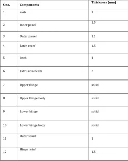
Table -1: door parts specifications
S no. Components Thickness (mm)
1 sash 1
2 Inner panel 1.5
3 Outer panel 1.1
4 Latch reinf 1.5
5 latch 4
6 Extrusion beam 2
7 Upper Hinge solid
8 Upper Hinge body solid
9 Lower hinge solid
10 Lower hinge body solid
11 Outer waist 1
[image:1.595.303.556.427.746.2]© 2016, IRJET | Impact Factor value: 4.45 | ISO 9001:2008 Certified Journal
| Page 256
Inner panel outer panel
Hinge reinf latch reinf
Outer waist sash
Fig -2: Parts of Automobile Door
2. MODELLING AND PRE-PROCESSING
Modelling and pre-processing comprises of some steps those are:
Setting up the cad model by importing IGES file in Hyperworks 13.0 (Optistruct solver)
Cleaning up the model
Meshing and refinement of the mesh
quality checks
2.1 Setting up:
A cad model which is in .IGES format is used in the Altair Hyperworks 13.0 software. This .IGES file type is the common type which can be used all types of software. This .IGES file is imported in the Hyperworks software for further use.
2.2 Clean-up:
In this step cleaning the geometry was done. When a cad model got imported, the model may have some free edges and free surfaces and cleaning the geometry helps to solve these issues.
Missing surfaces are made by fillet command.
Free edges are resolved by toggle the edges. After this we move to the next step which is splitting.
For a nice mesh it is recommended to split the surfaces by lines specially on those areas where some special features are their like holes, fillets, cut outs etc so we have to split surfaces to get better mesh.
A washer has to be in every hole so a washer circle is added to every hole and its value is taken 1.5d.
2.3 Meshing:
Mid-surface of the components are taken to be meshed.
Mixed type 2d meshing is used for shell parts.
Firstly washer area was meshed than fillets were meshed than surfaces were meshed.
Fillets had two elements.
Changing of element density is done several type to get smooth mesh.
The element size is taken as 5.
Tried to have same sized elements everywhere.
Opposite trias were removed by remeshing.
Trias at the corners are removed by drag trias clean up tool.
Rotating quads are avoided.
Trias are avoided at fillets.
Feature has been captured everywhere.
Project command is used for capturing feature.
Smoothing is done by smooth command.
Split and combine command is used make and break quads.
Solid map and elem offset is used for solid meshing.
Hexa-meshing is done in solid parts.
For 1d meshing rigids and spot weld are made in most of the areas.
Bolts are made by Hyperbeam and then placed in holes
2.4 Quality checks:
Quality checking is very vital as without this analysis cannot be done. Quality checks ensure us that the mesh is ok and we can go further now.
[image:2.595.38.276.104.414.2]© 2016, IRJET | Impact Factor value: 4.45 | ISO 9001:2008 Certified Journal
| Page 257
Incompatibility problems had to be resolved to get bettermechanism. These incompatibilities arise when degree of freedoms do not match with common nodes.
There are some quality standards which were followed:
Max trias < 5
Warpage < 15 degrees Aspect ratio = 5 Min size = 1 Max size = 20 Jacobian > 0.5
Max interior angle trias = 120 Max interior angle quads = 140 Min interior angle trias = 20 Min interior angle quads = 40
3. OBJECTIVE AND IMPLEMENTATION
The objective of my project is to increase the stiffness of the inner panel of an automobile door so as to reduce vibrations of it.
To increase stiffness we have to recall basic formulae of frequency in terms of stiffness i.e
F = (k/m) ^1/2
So as per formula frequency is directly proportional to stiffness and mass is inversely proportional to frequency so the task is to;
Maximize frequency
Minimize the mass
So the objective is to maximize the frequency at 3rd mode.
To implement the task certain steps had followed those are:
Assigning material and properties
Applying boundary conditions
Creating load step
Run the modal analysis
Introduce topography optimisation to it
Run again to get the bead areas
Making beads in meshed model
Run modal analysis again and see the results
compare the results
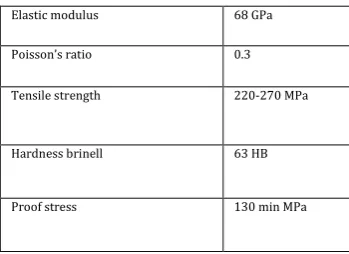
[image:3.595.346.521.133.260.2]4. MATERIAL USED
Table -2: properties of NG5754H22
Elastic modulus 68 GPa
Poisson’s ratio 0.3
Tensile strength 220-270 MPa
Hardness brinell 63 HB
Proof stress 130 min MPa
5. APPLYING LOADS AND SUPPORTS
Fig -3
:
constraint areasIn the above figure there are three areas mentioned. These three areas have bolt connections as 1-d elements and these elements are given constraints in every direction.
In boundary conditions three constraints (SPC) are made and these constraints are constraint in all the direction.
An EIGRL load collector is formed to run modal analysis.
EIGRL – Real Eigenvalue Extraction Data, Lanczos
Method
Defines data needed to perform real eigenvalue analysis (vibration or buckling) with the Lanczos Method.
No. of modes = 35
[image:3.595.308.558.331.495.2]© 2016, IRJET | Impact Factor value: 4.45 | ISO 9001:2008 Certified Journal
| Page 258
As we are attacking to 3th mode so in mode we put
3.
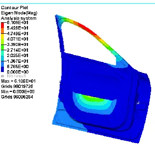
6. INITIAL MODAL ANALYSIS RESULT
This is the initial modal analysis result of 3rd mode i.e lateral
bending mode. The above fig shows that the upper part of the door is in high vibration and some vibrations are seen at the corners. Breathing vibration is also seen.
Fig -4: Modal Analysis at 3rd mode (30.49 Hz)
Breathing vibration is not our concern as the modal analysis shows the free vibration and in real life the upper portion of the door which is sash part and the corners of inner panel are our concerned areas. So in this areas stiffness is needed to reduce vibrations and lateral bending. For that topography optimization is done to get the areas which we have to increase stiffness.
7. TOPOGRAPHY OPTIMIZATION
IMPLEMENTATION AND MAKING BEADS
Design variable topography has been created
Bead parameters are declared h = 12, w = 5.
Pattern grouping: 1-pln sym, linear and circular which act as manufacturing constraint
Two responses are declared, frequency and mass.
Minimizing mass used as objective.
In dconstraint, lower bound is given 31hz which means frequency should be higher than that and the value is set by knowing the frequency of 3rd mode as
it is coming 30.49 so 31 is used.
Now for best results bead parameters are changed and also other pattern grouping options are tried like 1- pln sym, linear and circular.
Out of three manufacturing constraints, 1-pln sym gives the best result and the result is shown above.
In the below fig the left side picture shows where the beads should be given and the right side picture shows the modal analysis result after giving beads.
Fig -5: Topography Optimization results (34.1 Hz)
So by this way we got the areas where we have to give beads and the results we got after giving beads.
As we have seen above that the 3rd mode of modal analysis of
the door initially have 30.49 Hz frequency but after topography optimization the frequency raised upto 34.1 Hz.
[image:4.595.314.565.180.339.2]Now our role is to make beads same as the shown above.
Fig -6:Door with beads
Fig 6 shows how the beads made and fig 7 shows the modal analysis result after giving beads to the door.
[image:4.595.36.197.214.364.2] [image:4.595.309.503.504.655.2]© 2016, IRJET | Impact Factor value: 4.45 | ISO 9001:2008 Certified Journal
| Page 259
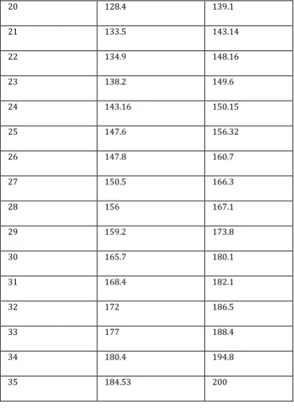
Fig-7: Final Modal Analysis of door with beads (33.4 Hz)Table -3: Comparison of both the modal analysis in terms of
frequency.
MODE NUMBER F (INITIAL) in Hz F (FINAL) in Hz
1 3.89 3.88
2 22.2 29
3 30.49 33.4
4 42.5 43
5 45.5 55.5
6 55 59.5
7 59.3 63.4
8 76.2 80
9 79 83.3
10 83 84.4
11 84 89.5
12 85 98.2
13 89 105.4
14 98.6 112
15 105.3 118.8
16 107.8 125
17 112.6 131.3
18 117.3 132.4
19 120 138.2
20 128.4 139.1
21 133.5 143.14
22 134.9 148.16
23 138.2 149.6
24 143.16 150.15
25 147.6 156.32
26 147.8 160.7
27 150.5 166.3
28 156 167.1
29 159.2 173.8
30 165.7 180.1
31 168.4 182.1
32 172 186.5
33 177 188.4
34 180.4 194.8
35 184.53 200
8. CONCLUSIONS
Fig -8: Final Door with appropriate beads
This is the final selected door beads which reduce the vibration of sash part which is undergoing lateral bending and also increases frequency.
By this solution three objectives are fulfilled those are:
1) This type of beads can be easily manufactured.
[image:5.595.309.522.99.398.2] [image:5.595.37.235.118.311.2]© 2016, IRJET | Impact Factor value: 4.45 | ISO 9001:2008 Certified Journal
| Page 260
3) Lateral bending of the door is reduced and also thevibration at sash part is also reduced.
Table-4: comparison between initial and final results
Objective Before optimization After optimization
Frequency of 3rd mode (Hz) 30.49 33.4
Mass (kg) 10.767 10.788
ACKNOWLEDGEMENT
I sincerely thank Tata Technologies, Pune, for giving us the opportunity to work and learn in their esteemed company. I would like to thank my college, JECRC Jaipur for providing me opportunity to have an internship here.
I am highly indebted to Mr Indranil Bhattacharyya sir, SME, TATA Technologies, for his guidance as well as for providing necessary information regarding the research work.
I am highly indebted to Ms Sayali Ketkar mam, CAE analyst (durability), TATA Technologies, for her limitless assistance and guidance throughout my internship.
I would like to express my gratitude towards my parents for their encouragement in the due course of this project.
My thanks and appreciations also go to employees of Tata Technologies who have willingly helped me out with their abilities specially Harshal sir, Chinmay sir, Waseem sir and Avinash sir.
REFERENCES
[1] Practical Aspects of Finite Element Simulation – A Study Guide(Altair Academic Program)
[2] Practical Aspects of Structural Optimization –A Study Guide (Altair Academic Program)
[3] Automobile door design using Structural Optimization & design of Experiments – K H Lee , S I Song , G J Park [4] Multi Objective reliability based Optimization for design
of a vehicle door Jianguang Fang , Qing Li , Gao Y K [5] Altair Optistruct Manual
[6] David Roylance, Finite Element Analysis, Department of Material Science and Engineering, Massachusetts Institute of Technology, Feb 28, 2001.
[7] Altair Hyper Mesh Tutorials
[8] https://en.wikipedia.org/wiki/Vehicle_door