* *
*
CORVUS SYSTEMS (TM)*
*
CORVUS SYSTEMS, Inc. warrants all its products (other than
software which is sold "AS IS") for a period of 180 days from the date of purchase from any authorized Corvus Systems dealer.
Should the product fail to be in good working order at any time during this period, Corvus Systems will, at its option, repair or replace this product at no additional charge except as set forth below. Repairs will be performed and non-functioning parts replaced either with new or reconditioned parts to make the product function according to the company standards and
specifications. All replaced parts become the property of Corvus Systems, Inc. This limited warranty does not include service to
repair damage to the product resulting from accident, disaster, misuse, abuse or modifications that are unapproved by Corvus Systems.
Limited Warranty service may be obtained by delivering the
product during the 180 day warranty period to Corvus Systems with proof of purchase date. YOU MUST CONTACT CORVUS CUSTOMER SERVICE TO OBTAIN A "RETURN MERCHANDISE AUTHORIZATION" PRIOR TO RETURNING THE PRODUCT. THE RMA (RETURN MERCHANDISE AUTHORIZATION) NUMBER
ISSUED BY CORVUS CUSTOMER SERVICE MUST APPEAR ON THE EXTERIOR OF THE SHIPPING CONTAINER. ONLY ORIGINAL OR EQUIVALENT SHIPPING MATERIALS MUST BE USED. If this product is delivered by mail, you agree to insure the product or assume the risk of loss or damage
in transit, to prepay shipping charges to the warranty service location and to use the original shipping container. Contact Corvus Systems or write to the Corvus Systems Service Center, 2100 Corvus Drive, San Jose, CA, 95124 prior to shipping equi pment.
ALL EXPRESS AND IMPLIED WARRANTIES FOR THIS PRODUCT,
INCLUDING THE WARRANTIES Of' MERCHANTABILITY AND FITNESS FOR A PARTICULAR PURPOSE, ARE LIMITED IN DURATION TO A PERIOD OF 180 DAYS FROM DATE OF PURCHASE, AND NO WARRANTIES, WHETHER EXPRESS OR
I~PLIED, WILL APPLY AFTER THIS PERIOD. SOME STATES 00 NOT ALLOI-J LIMITATIONS ON HOW LONG AN IMPLIED WARRANTY LASTS, SO THE ABOVE LIMITATIONS MAY NOT APPLY TO YOU.
IF THIS PRODUCT IS NOT IN GOOD WORKING ORDER AS WARRANTED ABOVE, YOUR SOLE REMEDY SHALL BE REPAIR OR REPLACEMENT AS
PROVIDED ABOVE. IN NO EVENT WILL CORVUS SYSTEMS BE LIABLE TO YOU FOR ANY DAMAGES, INCLUDING ANY LOST PROFITS, LOST SAVINGS OR OTHER INCIDENTAL OR CONSEQUENTIAL DAMAGES ARISING OUT OF THE USE OF OR INABILITY TO USE SUCH PRODUCT, EVEN IF CORVUS SYSTEMS OR AN AUTHORIZED CORVUS SYSTEMS DEALER HAS BEEN ADVISED OF THE POSSIBI-LITY OF SUCH DAMAGES, OR FOR ANY CLAIM BY ANY OTHER PARTY.
SOME STATES 00 NOT ALLOW THE EXCLUS ION OR LIMITATION Of'
INCIDENTAL OR CONSEQUENTIAL DAMAGES FOR CONSUMER PRODUCTS, SO THE ABOVE LIMITATIONS OR EXCLUSIONS MAY NOT APPLY TO YOU.
Part Number: 7100-05759 Release Date: March 1984 Revision: A
This equipment has been tested with a Class A computing device and has been found to comply with Part 15 of FCC Rules. Operation of this equipment in a residential area may cause unacceptable interference to radio and TV reception requiring the operator to take whatever steps are necessary to correct the interference.
NOTICE
Corvus Systems, Inc. reserves the right to make changes in the product described in this manual at any time without notice. Revised manuals will be published as needed and may be purchased from authorized Corvus Systems dealers.
This manual is copyrighted, all rights reserved. This document may not, in whole or in part, be copied, photocopied, reproduced, translated, or reduced to any electronic medium or machine-readable form without prior consent, in writing, from:
Corvus Systems, Inc. 2100 Corvus Drive San Jose, CA. 95124
Telephone: (408) 559-7000 TELEX: 278976
Copyright (c) 1984 by Corvus Systems, Inc.
Corvus Systems (TM), Corvus Concept (TM), Transporter (TM), Omninet (TM), LogiCalc (TM), EdWord (TM), Constellation (R), and Mirror (R) are trademarks of Corvus Systems, Inc.
OmniDrive Diagnostic Guide
TABLE OF CONTENTS
iii
Getting Started... 1
How This Guide' Is Organized... 1
Usage. • • • • • • • • • • • • • • • • • • • • • • • • • • • • • • • • • • • • • • • • • • • • • • • • • 2 Software Required •••••••••••••••••••••••••••••••••••••• 4 Olapter 1: Overview of DmniDrive Diagnostics •• 5 The OmniDrive Indicator Lights ••••••••••••••••••••••••• 5 Entering the Diagnostic Program... 8
From Diskette ••••••••••
.
.
. .
. .
.
.
.
. . .
. .
. . .
.
.
.
. .
. .
. . . .
.
9From Constellation II •••••••••••••••••••••••.••••••• 10 Selecting the Drive ••• 10 Chapter 2: Firmware Diagnostics •••••••••••••••••••••••••• 15 Version Check ••••••••••• 15 Updating the Firmware •••••••••••••••••••••••••••••••••• 17 Olapter 3: Hardware Diagnostics ••
...
19Exercising the Heads •••••
...
19Checking for Bad Tracks.
...
20Parking the Heads •••••••
...
22Chapter 4: Changing OmniDrive Parameters •.•••••.••••••••. the Parameters •••••••••••
...
ListingChanging the Interleave Factor •••
...
Adding Spare Tracks •••·
... .
Listing the Table ••
·
... .
Adding Tracks ••••.
.
. .
. .
. . .
. .
. . .
.
.
.
. .
. .
.
. . . .
.
.
.
. .
.
. . .
Removing Tracks ••••·
... .
Clearin9Read After
the Table.
·
... .
Wr ite •••
.
. . . .
. .
. . .
.
.
. . . .
.
. .
. .
. .
. . . .
. . .
.
. .
. . .
Saving Changes •••••
. . . .
.
.
.
.
. .
. . .
.
. .
. . .
.
.
. . .
.
. .
. . .
.
25 26 27
29
30 31
32
33
34
35
<llapter 5: Formating the OmniDrive •••••••••••••••••..•••. 37
Appendix A: Diagnostic Records •••••••• 41 System Manager's Diagnostic Record ••••••••••••••••••••• 41 Spare Track Table •••••••••••••••••••••••••••••••••.•••• 42
OmniDrive Diagnostic Guide
GETTING STARTED
]
This guide covers the diagnostic program for the OmniDrive mass storage system when used with the Corvus Concept personal workstation. This program is used to detect and correct
certain types of hardware and software problems that may develop.
Contact the Corvus Customer Service Department with problems beyond the scope of this guide. Back up the drive on a regular basis to avoid loss of valuable data. It is
recommended that a backup is done before using some options in the diagnostic program.
The diagnostic program should be used only by the person responsible for maintaining the drive, the system manager. A password protection system is used to limit access to the diagnostic program. The system manager should read this guide completely before using the diagnostic program.
All regular users should avoid using the network when the diagnostics program is in use. Additionally, it is suggested that a single computer be connected directly to the OmniDrive using a convenience connector.
HOW THIS GUIDE IS ORGANIZED
Chapter 1 describes the diagnostic tools available, including indicator lights and diagnostic problems. The chapter also explains entering the diagnostic program from Constellation II or when using diskettes.
Chapter 2 explains how to check and update the firmware. Chapter 3 describes how to exercise the heads and find media defects on the OmniDrive.
Chapter4 explains how to change the parameters, including the interleave factor, spared tracks, and the
read-after-write option.
Chapter 5 explains how to format the OmniDrive.
Appendix A contains two forms for recording diagnostic changes and updates.
OSAGE
Throughout this guide, type means to enter two or more characters on the Corvus Concept keyboard. Type all words, symbols, spaces and punctuation to the right of
the word type exactly as shown. Do not add or leave out punctuation marks at the end of a statement.
Example:
Type /CCUTIL/FUTIL
Do not type the spaces between type and the first character to its right, a slash in the above example. Enter characters in either upper or lower case.
Throughout this guide, press means to enter a single character or symbol on the Corvus Concept keyboard. When a key top symbol is used, press the key to which it
refers. Do not type out each letter of the word in the key top symbol.
Examples: Press Y
Press (RETURN]
When the command press or type appears in a sentence or paragraph, type in the information indicated.
Example:
Type the filename and press (RETURN].
At the top of the Corvus Concept keyboard are 10 function keys, numbered Fl through FlO. The function key labels display across the bottom of the Corvus Concept screen: when a function is not associated with a key, a blank
OmniDrive Diagnostic Guide 3
space replaces the label. The function key labels appear in instruction~ throughout this guide. Use the labels like key top symbols.
The labels change with each program. Within a program, each function key represents up to four separate
functions. To call a function, press a specific combination of keys; use the function, (SHIFT] and
(COMMAND] keys.
When the (COMMAND] key is pressed, up to 20 new functions are displayed. The original function key labels on the screen disappear and are replaced by new labels.
To call the first of the four possible functions associated with a key, simply press the function key. For example, if the guide states, ·Press (SetVol),· from the dispatcher level, press (F4).
To call the second function, hold down the [SHIFT) key and press the proper function key. For example, if the guide states, ·Press (Exit),· from the file manager program, press [SHIFT) and (FlO) at the same time. To call the third function, hold down the [COMMAND) key and press the proper function key. For example, if the guide states, "Press [MountMgr),· from the dispatcher level, press (COMMAND) and [F9] at the same time.
To call the fourth function, hold down the [COMMAND] key and the (SHIFT] key and press the proper function key. For example, if the guide states, ·Press (Reboot)," from the dispatcher level, press (COMMAND), [SHIFT] and [FlO] at the same time.
For clarity, this guide always uses the function key labels rather than the key number. The instruction Press [ListVol), for example, clearly implies listing a volume; the instruction Press (F5), however, may be confused with the other functions called by pressing a combination of (F5] and other keys.
The variables x.xx on the screen display stand for
software version numbers.
The convenience connector refers to the small plug used to connect two tap cables together. The connector was supplied with the OmniDrive.
iSOFTWARE REOUIRED
The diagnostic program ODIAG and related files containing the firmware and the diagnostic data block file are found on one of the distribution diskettes. For 8-inch
diskettes, these files are on the FDIAG diskette. for software on 5-1/4 inch diskettes, the files are on the FBOOT diskette.
ODIAG
FODRx.x.DATA OD.DIAG.DATA
OmniDrive diagnostics program Firmware update file
Data file for diagnostics program These files may also be found in the volume CCUTIL after the drive has been updated.
OmniDrive Diagnostic Guide 5
I
OVERVIEW OF I
OMNIDRIVE DIAGNOOTICS I I
I
I
This chapter briefly describes the diagnostic program, and is a helpful starting point for identifying and correcting
problems. First the drive indicator lights are explained, then there is a table of problems and possible solutions. The chapter ends with the steps necessary to enter the diagnostic program from either the OmniDrive or the FDIAG diskette in case the drive is not accessable.
THE OMHIDRIVE INDlCA"l'OR LIGB'l'S
The OmniDrive has three indicator lights on the front panel to show the status of the drive. The left light is the fault indicator light; the center light is the busy light, and the right light is the ready light. When the drive is ready, only the right light should be on.
During normal operation, the center and right lights flicker as data is transferred to and from the drive. The illustration below shows these indicator lights:
QmniPr~lndicator LightR
The OmniDrive takes approximately one minute to corne ready after it is turned on. If the drive does not corne ready, reset the drive by turning it off and after a moment turning it on again.
i
OmniDrive Diagnostic Guide
The table below shows common problems and their solutions.
Symptom Possible Problem Remedy
7
~---+---+---o indicat~---+---+---or lightsl P~---+---+---ower c~---+---+---ord n~---+---+---ot I Properly connect n disk I properly connected I power cord
---+---.--+---ndicator lights I Drive error I Reset drive
unction yet ready
+---..
-+---ight doesn't I Improper firmware I Replace firmware (Seetay on I I firmware section
· I I below)
r---+---·--+---'
eadY light on I Improper hardware I Check hardware setup
~;m~~~~~~:rw~~~notl-~~:~~---
.•-l-~~~-~~~~~~:_~~~~~::
__
rive I Problems in inter- I Properly setinter-I leave factor I leave factor (see
· I I section below)
t---+---+---i
eadY light on and I Media defects I Check for media omputer can commu-I I defects (See section ·icate with the I I below)rive but inter- I I
ittent problems
+---+---· I Problems in inter- I Properly setI leave factor I interleave factor
I I (See section below)
+---+---
I Improper firmware I Replace firmware (seeI I firmware section
I I below)
+---+---t---~ther problems I I Call Corvus
I I I Customer Service
+---+---+---~o[VUS
ConceptENTERING THE DIAGNOSTIC PROGRAM
The system manager runs the diagnostic program using the computer connected to the OmniDrive. No other users should be using the network.
Before running the diagnostic program, the OmniDrive should be connected directly to one computer using the convenience connector to link the tap cables.
First, turn off all equipment. The computer can not be more than 30 feet from the OmniDrive, otherwise the tap cables for the two devices could not be connected.
Next, unplug the OmniDrive tap cable from its network tap box. The other end of the tap cable should remain
connected to the OmniDrive. Insert the free end of the tap cable into one end of the convenience connector. For more information, refer to the OmniDrive Setup
Instructions.
Unplug the tap cable from the network tap box of the computer that will run the diagnostic program. Insert the free end into the other end of the convenience connector. For more information, refer to the Corvus Concept Personal Workstation lnatallatiOD Gui~.
The drive must be backed up before certain diagnostic procedures are performed if you wish to save data on the drive. As a precaution, you should back up the drive before using the diagnostic program to perform any procedure.
The ODIAG program and the related data files must be in the current volume. If the program cannot find the data block file to access for information, an error message appears:
Unable to open Diag block file OD.DIAG.DATA Pascal I/O error: 10
File not found.
Type <space> to continue •••
OmniUrive Diagnostic Guide 9
Before running this program be sure to set the current volume to CCUTIL if running ODIAG from a drive; FDIAG if
running ODIAG from B inch diskette; FBOOT if running ODIAG from 5-1/4 inch diskette.
FROM DISKETTE
If the drive cannot be used, the diagnostic program must be run from diskette. Normally, the diagnostic program is run from the floppy diskette containing the diagnostic utilities. For 8-inch software, this is the FDIAG
diskette. The 5-l/4-inch diskette is the FBOOT diskette. The OmniDrive should be connected directly to the
computer using the convenience connector, as described above.
To enter the program, boot the computer using the FBOOT diskette.
From the 5-1/4 inch diskette, do this:
After the Corvus Concept dispatcher labels appear,
Type ODIAG Press [RETURN)
From the 8 inch diskette, do this:
After the Corvus Concept dispatcher labels appear,
Type FDIAG Press [SetVol)
Put the FDIAG diskette in the diskette drive.
Type ODIAG Press [RETURN)
The ODIAG program begins. Skip to the section "Selecting the Drive."
FROM boNSTELLATION II
The diagnostic program can also be run from the
Omnidrive, or another drive. The OmniDrive should be connected directly to the computer using the convenience connector, as described above.
Log on as the system manager. Press [Const II)
The Constellation II main menu appears. It is described in the Corvus CODcept System Manager's Guide.
Select the maintenance utilities. Press [Maint)
The maintenance utilities menu appears. Press [OdrvDiag)
The ODIAG program begins. Continue with the next section "Selecting the Drive."
SELECTING THE DRIVE
After entering the program the screen display is similar to:
DISK DIAGNOSTIC [x. xx) Slot g 5
Select Drive ServCer~ 0 Slot 3: a Corvus 8" floppy interface Slot 5: an OMNINET interface
Enter slot number : 0
pmniDrive Diagnostic Guide 11
The slot and server address for the drive are shown, if the drive responds. All active devices connected to the Corvus Concept are then listed.
In some cases, no devices may be shown. Check all hardware connections. The ODIAG program allows you to specify a non-responding slot location. The OmniDrive will be in slot 5, the Omninet slot, since it is a network device.
Press 5
Press (RETURN)
The prompt for the server number (the Omninet address) appears next:
~-
--Enter server number : 0
Enter the server number of the OmniDrive and press (RETURN).
If the address is wrong or the OmniDrive does not
respond, you are prompted to press (SPACE). The prompts for slot and server numbers appear again. Enter the correct slot and server numbers.
If the drive has not been initialized, the main menu of the diagnostic program appears next. If the OmniDrive was initialized, the server name and drive name appear with the prompt below.
Selected drive is server SERVERO Continue (YIN)?
Press Y
qorvus Concept
; drive DRIVEl
The system window displays:
-~
--DISK DIAGNOSTIC(x.xx] Slot: 5 Main Menu Server: 0
v -
Version check M - Modify Parametersx -
Exercise HeadsC - Check for Bad Tracks U - Update Firmware on Drive F - Format Corvus Drive P - Park Heads for Shipment S - Select Drive
E - Exit
The command window displays:
+---+
I IIPlease select an option: I
+---+
The function key labels for ODIAG are:
OmniDrive Diagnostic Guide
PI P2
ODIAG
F3 F4 F5
+---+---+---+---+---+
I I I I , I+---+---+---+---+---+
IVrsion IParam IExrcis IUpdate I I+---+---+---+---+---+
F6 F1 F8 F9 FlO
+---+---+---+---t---+
I I I , I ,+---+---+---+---t---+
I ICRCtst IFormat IPark IExit I+---+---+---+---t---+
ODIAG with (COMMAND) held down
FI F2 F3 F4 F5
+---+---+---+---+---+
I I I I I I+---+---+---+---+---+
ISeIDrv I , I , I+---+---+---+---+---+
F6 F1 F8 F9 FlO
+---+---+---+---t---+
I I I I I I+---+---+---+---t---+
I I I I I ,
+---+---+---+---+---+
You can use the letter or the function key to select an option from the main menu.
13
!Corvus Concept
This page intentionally left blank.
OlOniDrive Diagnostic Guide 15
I FIRMWARE I DIAGNOOTHS I 2
I
I
This chapter presents the two diagnostic procedures for
OmniDrive mass storage system firmware. The firmware acts as an interpreter for drive commands.
Corvus periodically issues new versions of drive controller code referred to as firmware. Corvus firmware version number FODR1.4 or later allows an OmniDrive to operate with a Corvus Concept personal workstation.
There are two ODIAG options that apply to the firmware: the version check, and firmware update. The Version option displays various drive information including the firmware version number, the version number of the firmware data block file, the drive's size, capacity, ROM version, the number of cylinders, tracks per cylinder, and sectors per track.
The Update option writes the firmware file onto the drive. This option is used when the current firmware version becomes damaged, or when updating the drive to contain a later
firmware version.
VERS ION CD ECI
The version check should be performed before other diagnostic tests. Write down the results for future reference.
Press (Vrsion)
The screen below shows a typical version check:
---DISK DIAGNOSTIClx.zx] Slot: 5 Ver sion Check Server ~ 0
Drv P/V Capaci ty Size/Rev SPT TPC CPD
---
---1 P 32472 16MB/0 18 6 306 ROM DB Firmware
---S 4 FODR1.4
--
CONST I I-
01/84 Press <space> to continue.Drv This is the drive number, which is always 1 for an OmniDrive.
P/V This shows if the drive is considered a physical or a virtual drive. An OmniDrive should always show P for physical.
capacity The number shown for capacity is the number of 5l2-byte sectors available for data storage. Size/Rev This is the nominal drive size and type of
drive. The size shown is the rated size of the drive. The rev shown should always be 0, for OmniDrive.
SPT
TPC
CPD
Corvus Concept
This shows the number of sectors per track. The OmniDrive is divided into sections so that it can access information quickly. The drive is divided into cylinders, which are divided into tracks, which in turn are divided into sectors.
This shows the number of tracks per cylinder. See SPT above.
This shows the number of cylinders per drive. See SPT above.
OmniDrive Diagnostic Guide 17
ROM This shows the level of the ROM chips contained in the drive. These chips contain special code and should be changed only by authorized
service centers.
DB This shows the version of the ODIAG.DATA block used by the drive firmware. This data file contains information necessary for the drive to operate.
Firmware This is the version of firmware found on the drive. The date shown is the release date for the firmware. The firmware version and
release date should be written down for later use.
Write down the information shown in the version check for later use.
Press [SPACE)
'I'he ODIAG main menu reappears.
UPDATING THE FIRMWARE
The Update option of the main menu of the diagnostic program is used to update the firmware on the drive. The firmware code is contained in the FODRx.x.DATA file, where the x.x represents the version number. This file is found on the same diskette as the diagnostic program. To update the firmware,
Press [Update)
The system window displays:
DISK DIAGNOSTIC[x.xx) Slot~ 5 Update Firmware Server ~ 0
Change drive tables? N
Changing the tables clears the spare track table, sets the interleaving factor to 9, and sets the
read-after-write to OFF. The spare track table should never be cleared.
Press (RETURN)
The system window displays:
Enter firmware file name: FODRx.x
Accept the suggested file name. Press (RETURN]
The system window displays:
Reading firmware from FODRx.x.DATA
...
Firmware written.
Press <space> to continue.
~-
--Press (SPACE)
The ODIAG main menu reappears.
OmniDrive Diagnostic Guide 19
HARDWARE DIAGNOSTICS 3
The diagnostic program has two options to check the drive hardware: exercising the heads, and checking the media surfaces for defects causing CRC errors. A third option allows parking the heads of the drive before shipment.
EXERCISING THE BEADS
Exercising the heads checks the movement of the
read-write heads across the platters in the disk drive mechanism. The primary purpose of this test is to make sure the heads move freely. This test also performs a simple check for hard and soft data errors. A hard error in this test indicates that the head could not find the tracks on the platter surface. A soft error is a
read-write error that is detected and corrected by the drive controller.
If hard errors are found, check for bad tracks and their locations using the CRCtst option of the diagnostic program. If a few, or no, soft errors appear then the drive is in operating condition. A large number of soft errors may indicate a problem with the firmware, or that the sector interleave factor is set incorrectly.
To exercise the heads, Press (Exrcis]
The system window displays:
DISK DIAGNOSTIC(x.xx] Slot: 5 Exercise Heads Server: 0
Fress <space> to stop test.
·
... .
·
... .
• • • • • • • • • • • • • • • • • II • • • • • • • • • • • • • • • • • • • • • •
The exercise statts immediately. screen as each pass is finished. minute,
Dots appear on the After approximately a
Press [SPACE]
The system window displays:
Error Summary:
Number of passes 128
Number of soft errors: 0 Number of hard errors: 0 Press <space> to continue.
Press [SPACE]
The ODIAG main menu reappears.
CHECKING POR BAD TRACKS
Select the CRCtst option to perform a cyclical redundancy check of the magnetic media on the drive platter surfaces to locate possible defects. Media defects can produce
OmniDrive Diagnostic Guide 21
hard errors that cannot be corrected by the drive controller. These defects may cause bad tracks on the drive. This diagnostic is performed if hard errors appear in one of the other tests, if the drive has been subjected to sudden impact.
Check for bad tracks at least three consecutive times if any bad tracks are discovered in the first test. The program tries to correct the problem itself, and the track may not appear the second or third time. If a track appears to be bad again, then it probably is defective and should be corrected. Go to the section "Adding Spare Tracks" in Chapter 4 to correct bad tracks. To check for bad tracks,
Press [CRCtst)
The system window displays:
---DISK DIAGNOSTIC[x.xx] Slot: 5 Check For Bad Tracks Server: 0
Check for bad tracks (YIN)?
Press Y
The screen displays:
This test takes from 1 to 6 minutes. Test in progress
---The test is performed automatically. I f the test found no bad tracks, the system window displays:
-~
--No blocks with CRC errors found Press <space> to continue.
If bad tracks are found, the screen display is similar to:
3 block(s) with CRC errors
Head Cylinder Sector Track
---
---1 229 6 916
1 170 13 600
1 280 7 1120
Press <space> to continue.
write down the information displayed for each bad track.
Press [SPACE)
The ODIAG main menu reappears. Run the CRC check again as necessary, and then add spare tracks as needed.
PARKING THE HEADS
Parking the heads positions the heads over an area on the disk that contains no data. A sudden impact to the drive will not cause the heads to bounce against the media surface and damage areas with data. The heads should be parked before the drive is shipped or transported for
~xtended distances.
When the heads are parked, the drive heads are
deactivated and the indicator lights change from ready to busy. The drive must be reset by tUrning it off, then
OmniDrive Diagnostic Guide
on, before it can be used again. The heads are automatically activated when the drive is reset. To park the heads,
Press (park]
The system window displays:
23
---DISK DIAGNOSTIC(x.xx] Slot: 5 Park Heads Server: 0
Park Heads (YIN)?
Press Y
The screen displays:
Heads parked.
Press <space> to continue.
Press (S PACE]
The ODIAG main menu. Exit the diagnostic program and turn off the drive to prepare it for shipping or transportation.
This page intentionally left blank.
OmniDrive Diagnostic Guide 25
CHANGING OMNIDRIVE
PARAMETERS 4
Three OmniDrive mass storage system parameters can be changed: the interleave factor, the spared track table, and the
read-after-write option. These three parameters are stored in the drive tables in the firmware. The default settings are:
Interleave factor - 9
Spared Track Table - No Spared Tracks Read After Write - OFF
WARNING: All data on the drive sbould be backed up before the interleave factor or the spared track table is
modified or changed. From the ODIAG main menu, Press (Par am]
The modify parameters menu appears:
DISK DIAGNOSTIC[x.xx) Modify Parameters
L - List Parameters I - Interleave Factor T - Spare Track Table R - Read After Write S - Save Changes
E - Exi t
The function keys display:
Slot: 5 Server: 0
Modify Paraaeters
Fl F2 F3 F4 F5
+---+---+---+---+---+
I I I I I I
+---+---+---t---t---t
I[.ist I l i S p Trk IInterl I+---+---+---t---+---t
F6 F7 F8 F9 FlO
+---+---+---+---t---t
I I I I I I
+---+---+---+---t---+
ISave IRafterW I I I Exit I+---+---+---+---+---+
LISTING THE PARAMETERS
First list the parameters to determine the current settings.
Press [List]
OmniDrive Diagnostic Guide 27
The system window displays:
---Modify Parameters Slot: 5 List Parameters Server: 0
Spared Tracks 123 456 789
3 tracks are currently spared. 28 total tracks may be spared.
Interleave Factor: 9 Read After Write OFF. Press <space> to continue.
Press (SPACE]
The modify parameters menu reappears.
CHANGING THE INTERLEAVE FACTOR
The interleave factor determines the frequency at which the drive controller attempts to read data from or write data to sectors on the drive platters. For example, an interleave factor of 9 means that every ninth sector is written, while an interleave factor of 6 means every sixth sector is written.
The default interleave setting of 9 is the optimum setting for the Corvus Concept. For other types of computers, an interleave factor of 7 or 6 may yield better performance. Do not change the interleave factor without first consulting the Corvus Customer Service Department.
The entire drive must be backed up before the interleave factor is changed. The data is restored to the drive
after the new interleave factor is set. If the drive is not backed up first, the diagnostic program should be run from the floppy diskette to restore the original sector interleaving.
To change the interleave factor, Press (Interl]
The bell sounds and the system window displays:
---Modify Parameters Slot: 5 Interleave Factor Server: 0
The option you have selected may destroy data on the drive. Please make sure that you are talking to the proper drive.
Continue (YIN)?
To change the interleaving factor, Press Y
To exit, press N and (SPACE) to return to the modify parameters menu.
After pressing Y, the screen displays the current factor:
Enter interleaving: 9
Enter the value for the interleave factor designated by the Corvus Customer Service Department. For this example the interleave factor is set to 7.
OmniDrive Diagnostic Guide 29
---,---Enter interleaving: 7
The interleave factor is 7 Press (space> to continue.
Press [S PACE)
The modify parameters menu reappears.
ADDING SPARE TRACKS
The spare track table lists bad tracks that have been removed from use. Tracks containing media defects can be replaced with spare tracks. Each drive has a limited number of tracks that can be replaced. A written record of the spare track table should be kept for future use,
in case the table is cleared accidentally or the drive is reformatted.
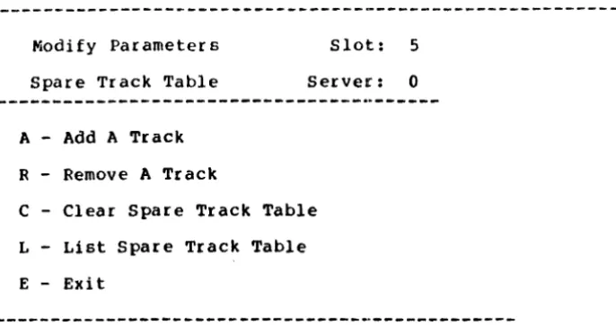
To select the spare track table option, Press [Sp Trk)
The system window displays the spare track menu:
[image:35.617.142.492.105.194.2]Modify Parameters Slot: 5 Spare Track Table Server: 0
A - Add A Track R - Remove A Track
C - Clear Spare Track Table L - List Spare Track Table
E - Exit
LISTING THE TABLE
First list the spare track table, and make a list of any tracks that have been spared. Keep this information for later use.
Press (List)
The screen display is similar to:
Spare Track Table Slot: 5 List Spare Track Table Server: 0
Spared Tracks 123 456 789
3 tracks are currently spared. 28 total tracks may be spared. Press <space> to continue.
[image:36.615.149.492.92.273.2]
OmniDri ve Diagnosti c Guide
Write down the information for future use. Press (SPACE]
The spare track menu reappears.
ADDING TRACItS
Adding tracks to the spare track table replaces a bad track with a good one. Tracks should be added to this table only if they are known to be bad. Perform a CRC test to verify the condition of tracks.
31
If bad tracks are found a method you may want to use is to back up the entire drive to another media, format the drive and perform a CRC test. After the CRC test is finished, spare the bad tracks, update the software, and then restore the drive data.
To spare a bad track, Press (Add)
The system window displays:
Spare 'I'rack Table Slot: 5 Add A Track Server: 0
Enter track number to be added:
Enter the track to be added to the spare track table. For example,
Type 321
Press (RETURN)
The screen display is similar to:
---Spared Tracks 123 321 456 789
4 tracks are currently spared. 28 total tracks may be spared. Press A to add another track or Press <space> to continue.
Press (SPACE)
The spare track menu reappears.
REMOVING TRACKS
The Remove option is used to remove tracks from the spared track table. Tracks removed from the table are then available for data storage use. Do not remove a track unless instructed to do so by the Corvus Customer Service Department.
To remove a track,
Press (Remove)
The system window displays:
Spare Track Table Slot: 5 Remove A Track Server: 0
Enter track number to be removed:
Enter the number of the track to be removed from the spare track table. For example,
OmniDrive Diagnostic Guide
'l'ype 321 Press (RETUHN]
The screen display is Similar to:
Spared Tracks 123 456 789
3 tracks are currently spared. 28 total tracks may be spared. Press R to remove another track or Press <space> to continue.
Press [SPACE]
The spare track menu reappears.
CLEARING THE TABLE
33
The [Clear] option is used to clear all tracks from the spare track table. All spare tracks should be recorded before the spare track table is cleared. Do not clear the table unless instructed to do so by the Corvus Customer Service Department.
To clear the table, Press (Clear]
The screen display is similar to:
---Spare Track Table Slot: 5 Clear Spare Track Table Server: 0
Spared Tracks 123 456 789
3 tracks are currently spared.
28 total tracks may be spared. This option will clear all tracks from the table.
Continue? (YIN)?
To clear the spare track table, Press Y
The system window displays:
No tracks are spared. Press <space> to continue.
Press [SPACE]
The spare track menu reappears. Press [Exit]
The modify parameters menu reappears.
READ-AFTER-WRITE
Read-after-write makes the drive read each sector after writing to it, to verify that the data was written
correctly. This adds to data reliability, but slows down
OmniDrive Diagnostic Guide 35
the drive. The drive normally has the read-after-write option OFF.
To change the current setting,
Press (RafterW)
The system window displays:
Modify Parameters Slot: 5 Read After Write Server: 0
Read after WRITE (YIN)?
Select the desired setting. For example, to turn the read-after-write ON:
Press Y
The system window displays:
Read After Write is ON. Press <space> to continue.
Press (SPACE]
The modify parameters menu reappears.
SAVING CHANGES
Changes made to the interleaving, spare track table, or read-after-write option must be made permanent by saving them. If the diagnostic program is terminated without
saving the changes, the changes will not be made on the OmniDrive.
Press [Save]
The system window displays:
---Modify Parameters Slot: 5 Save Changes Server: 0
You are about to destroy data on the disk. Continue (YIN)?
To save the changes, Press Y
To save the original settings, press N. The modify parameters menu reappears.
The system window displays:
Farameters updated.
Press <space> to continue.
Press [S PACE)
'l'he modify parameters menu reappears. Press [Exit)
The ODIAG main menu reappears.
OmniDriv~ Diagno&tic Guide 37
FORMATTING THE OMNIDRIVE 5
Formatting the drive clears all data from the drive, including the volume and file structure. After the drive has been
formatted, the firmware must be updated. It is recommended that a CRC test be performed after formatting and updating the firmware, and the spare track table be updated, i f necessary. Then restore the data after all the diagnostic procedures are completed.
WARNING: The Format option viII completely destroy all data on the drive. Back up the drive before starting the Format procedure, and restore the drive data after the procedure is completed. There is no vay to recover data destroyed during formatting.
If the drive does not come ready, but has the fault and busy lights on, it may need to be formatted. Run the diagnostic program from a floppy diskette. Then, select the Format
option to format the drive. If only the busy light is lit, or if the lights flicker on and off, the drive is probably in sound mechanical condition, but needs new software.
After formatting, update the firmware, run a check for bad tracks, modify the parameters as needed, then exit the
diagnostic program. When the drive is reset, it should come ready. If it does not, call the Corvus Customer Service Department or an authorized service center for assistance. From the ODIAG main menu,
Press (Format)
The bell sounds, and the system window displays:
---DISK DIAGNOSTIC[x.xx] Slot: 5 Format Drive Server: 0
---The option you have selected may destroy data on the drive. Please make sure that you are talking to the proper drive.
Continue (YIN)?
To continue the procedure, Press Y
The bell rings again and the system window displays:
Enter the format password
The fault and ready indicator lights should both be on. The password is ODFORMAT, used to prevent accidental formatting of the drive. The password does not displayed as it is entered. Type ODFORMA'l'
Press [RETURN]
The format procedure begins immediately, and the system window displays:
Format in progress. Format takes from 1 to 6 minutes.
OmniDrive ~iagnostic GuidE
'I'he busy light remains on during the format. When the for-matting procedure is finished, the computer bell rings again, and the system window displays:
39
---Format complete.
Enter firmware file name: FODRx.x
---~---
---To enter the firmware filename, Press [RETURN]
The firmware is written to the drive, and the system window displays:
Reading firmware from FODRx.x.DATA
Firmware written.
Press <space) to continue.
The Format procedure and firmware update is complete. Press [S PACE]
The ODIAG main menu reappears, and the function keys return. Now go to the section "Checking for Bad Tracks" in chapter 3 to find any bad tracks. Spare any bad tracks then proceed to the ~~Q~ OmniDrive System GeneratioQ~~ to
initialize the drive. After the drive has been initialized update the operating system and software and restore drive data.
This page intentionally left blank.
OmniDrive Diagnostic Guide 41
DIAGNOSTIC RECORDS A
SYSTEM MANAGER'S DIAGNOSTIC RBCORD
+---+---+
I Date I Diagnostic Performed I
+---+---+
11 I I
+---+---+
21 I I
+---+---+
31 I I
+---+---+
41 I I
+---+---+
51 I I
+---+---+
6 I I I
+---+---+
71 I I
+---+---i
S I I I
+---+---+
91 I I
+---+---+
10 I I I
+---+---+
111 I I
+---+---+
121 I I
+---+---+
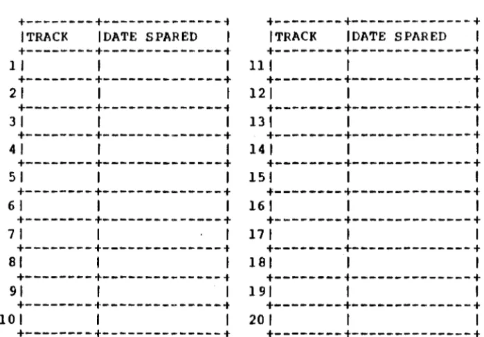
SPARE TRACK TABLE
+---+---i
t---+---+
I TRACK IDATE SPARED I ITRACK IDATE SPARED I
+---+---+
t---+---t
1 I I I 111 I I
+---+---+
+---+---t
21 I I 121 I I
+---+---i
t---+---t
31 I I 131 1 I
+---+---+
t---t---t
41 I 1 14 I I I
+---+---+
t---t---+
51 I 1 151 1 I
+---+---+
+---t---t
61 I 1 161 1 1
+---+---+
t---t---+
71 I I 171 I I
+---+---t
t---+---+
81 I I 181 I I
+---+---t
+---i---+
91 I I 191 1 I
+---t---t
t---+---t
10 I I 1 20 I I I