OPTIMIZATION OF BDD BY CHAOTIC EVOLUTION
ALGORITHM AND ITS APPLICATION IN TEST OF
STUCK-OPEN FAULTS IN DIGITAL CIRCUITS
1PAN ZHONGLIANG, 2CHEN LING
1
Department of Electronics, School of Physics and Telecommunications Engineering,
South China Normal University, Guangzhou 510006, China.
E-mail: [email protected]
ABSTRACT
The binary decision diagram (BDD) is an efficient graph representation of logic Boolean functions, it has wide applications in a lot of areas, such as computer science, circuit design and test. The size of binary decision diagram depends on the variable ordering which is used. A new approach is presented in this paper for the variable ordering and the optimization of binary decision diagrams, the approach is based on a chaotic evolution algorithm. The chaotic evolution algorithm proposed in this paper can combine the features of chaotic systems and evolutionary algorithm, and can take full advantages of both the stochastic properties and the global search ability. The application of the approach for the test of stuck-open faults in digital circuits is investigated, a test algorithm of stuck-open faults is proposed. The experimental results for a lot of digital circuits show that the binary decision diagrams with smaller number of nodes can be obtained by using the approach proposed in this paper, and the test vectors of open faults in digital circuits can be produced.
Keywords: Digital Circuits, Binary Decision Diagrams, Variable Ordering, Stuck-Open Faults, Test
Algorithm.
1. INTRODUCTION
A lot of problems in the computer science, artificial intelligence, the design and test of digital circuits can be expressed by a sequence of operations on logic Boolean functions. The binary decision diagram (BDD) is an efficient graph representation of Boolean functions, the logic Boolean manipulations can be performed by the developments of fast and efficient algorithms based on binary decision diagrams [1]. The BDD has wide applications, for instance, the representation and operation of set [2], circuit design and simulations [3,4], reliability analysis [5,6], etc.
The number of nodes in a BDD depends on the variable ordering which is used, therefore in order to reduce the complexity of problems being tackled, it is valuable to investigate the techniques that can get the BDDs with lower number of nodes. Ebendt et al discussed the lower bounds of BDD size, gave the new lower bounds in dynamic variable reordering [7], and investigated an approach based on weigh for the variable ordering of BDD, which used the goal-directed best-first search [8]. Nevo et
al discussed the dynamic BDD ordering in distributing system over a number of computers to improve ordering time and application time [9]. Rotaru et al used the cellular genetic algorithm for the optimization of variable ordering for reduced ordered binary decision diagrams [10].
Besides, for the specific applications of variable ordering, Yuchang [11] investigated the BDD variable ordering for reliability analysis of phased-mission systems, and evaluated the efficiency of variable ordering by using the fault trees having different sizes and structures. Iwasaki et al [12] investigated the variable ordering of the zero-suppressed BDD, and gave its applications in data mining.
of stuck-open faults in digital circuits is investigated, a test algorithm of stuck-open faults is proposed.
2. BDD AND VARIABLE ORDERING
The logic Boolean functions are the fundaments of digital circuits. Many problems in the design and test of digital circuits can be expressed by a sequence of operations on logic Boolean functions. The binary decision diagram(BDD) is a graph representation of logic Boolean functions, one main feature of BDD is that a lot of practical problems can be represented by the BDD with feasible sizes, this feature allows the development of fast and efficient algorithms to carry out logic Boolean manipulations. In the following, suppose all Boolean functions are expressed over the variables x1, x2, ⋅⋅⋅, xn.
The BDD is a directed acyclic graph that represents a Boolean function, it has two types of nodes: terminal nodes and nonterminal nodes. The terminal nodes are also called leaf nodes. Each leaf node is labeled 0 or 1 which corresponds to the value of the Boolean function. Each nonterminal node is labeled by one of the variables x1, x2, ⋅⋅⋅, xn, and has exactly two outgoing edges which are called a 0-edge and a 1-edge, respectively. The 0-edge corresponds to the case where the variable is assigned 0, the 1-edge corresponds to the case where the variable is assigned 1. Besides, there is a nonterminal node that is the unique source node, which is called the root node. Each path from the root node to a leaf node corresponds to a truth table entry where the edges in the path correspond to the value assignments of the Boolean variables.
For example, the BDD is shown in Fig.1 for the logic function
g
=
x
2⋅
x
3+
x
1⋅
x
2⋅
x
3 . In Fig.1, the 0-edge is shown by a dashed line, the 1-0-edge is shown by a solid line.The reduced ordered binary decision diagram (ROBDD) is defined as follows: The ROBDD is a BDD in which the input variables are ordered such that each variable in every path appears only once and appears in the same order. Each input variable is associated with an integer index which denotes its position in the ordering. One of the important properties of a ROBDD is that it is a canonical representation, i.e., if two logic Boolean functions are equivalent, then their ROBDDs are isomorphic.
Fig.1 The BDD Of Function G.
x
1x
2x
2x
3x
30 1
x
1x
2x
3x
5x
4x
6(a)
0 1
x
1x
3x
5x
4x
2x
6x
3x
4x
2x
2x
2x
5x
5x
5(b)
0 1
In the Fig.1, the variable ordering is x1<x2<x3, where the symbol < represents the ordering. For a given logic function, the number of nodes in its BDD depends on the variable ordering which is used. For example, let h=x1x2+x3x4+x5x6. The BDD of h is given in Fig.2(a) if the variable ordering is x1<x2<x3<x4<x5<x6. The BDD of h is shown in Fig.2(b) if the variable ordering is x1<x3<x5<x2<x4 <x6. The number of nodes in the Fig.2(a) and Fig.2(b) is 8 and 16, respectively.
Therefore, the choice of variable ordering largely influences the number of nodes in a BDD. In the following Section 3, a new approach is presented for the optimization of BDD, the approach can obtain the BDD with smaller number of nodes.
3. OPTIMIZATION OF BDD BY CHAOTIC EVOLUTION ALGORITHM
In this Section 3, the optimization of BDD by using a chaotic evolution algorithm is presented. The chaotic evolution algorithm combines the features of chaotic systems [13] and evolutionary algorithm [14,15], and can take full advantages of both the stochastic properties and the global search ability.
There are following three aspects for the implementations of the optimization of BDD by chaotic evolution algorithm: (a) The representations of individuals; (b) The definition of fitness function; (c) The implementation steps of chaotic evolution algorithm.
For the representation of an individual, an integer string with length n is used as the coding of an individual, where an individual is corresponding to a variable ordering of a BDD, the n denotes the number of variables in the BDD being considered. For example, for the BDD of a circuit, the integer string (6 7 1 3 5 2 4) is the representation of an individual, which is corresponding to the BDD under the variable ordering x6<x7<x1<x3<x5<x2< x4.
For the definition of fitness function, the fitness g(Z) of an individual Zis defined by the number of nodes in the BDD under the variable ordering corresponding to the individual Z.
In the following, the implementation steps of the optimization of BDD by chaotic evolution algorithm are given in detail.
The following chaotic system is used, which is the logistic map being defined by the following equation
yk+1= 4⋅yk(1−yk) k = 0,1,2, ⋅⋅⋅⋅⋅⋅. (1)
Where the yk∈[0,1], the yk is variable y at the k -th iteration. The chaotic map (1) has -the special features such as the stochastic property, sensitivity dependences on initial conditions, etc.
The procedure of the optimization of BDD by chaotic evolution algorithm is given as follows. Let P(k) denote a population consisting of N
individuals.
Algorithm 1
Step 1. Set k=0;
Step 2. Generate the initial population P(0) which consists of N individuals;
Step 3. Randomly select M individuals from the population P(0), perform the local searches for the
M individuals by using the Algorithm 2, and produce new M individuals. Set k:=k+1, and use the new M individuals to replace the M individuals selected from the population P(0). Thus the new population P(k) is produced.
Step 4. Generate a lot of new individuals by performing the selection, crossover and mutation operations for the population P(k). Let the ϕ1 is the set of the new individuals.
Step 5. Evaluate each new individual in the ϕ1, i.e., calculate the fitness of each new individual.
Step 6. Constitute the population ψ1 that consists of the M individuals with higher fitness in the union of the P(k) and the ϕ1.
Step 7. Randomly select M individuals from the population ψ1, perform the local searches for the M individuals by using the Algorithm 2, and produce
M newindividuals. Let the ϕ2 is the set of the M new individuals.
Step 8. Evaluate each new individual in the ϕ2.
Step 9. Produce the population ψ2 being made up of the M individuals with higher fitness in the union of ψ1 and the ϕ2. The new population P(k+1) is the population ψ2.
Step 10. If the stopping condition is satisfied, then the procedure is terminated, otherwise, set
k:=k+1, go to Step 4.
corresponds to a variable ordering of a BDD. Therefore, the methods of the crossover and mutation operations are as follows. For the crossover operation, produce the offspring by choosing the part between the cut positions from one parent and preserving the position and order of as many variables as possible from the second parent. For example, let two parent individuals be (4 1 3 2 6 5 7) and (3 2 6 1 7 4 5). If the cut positions are the third and fourth, then the new offspring individuals are (4 2 6 1 3 5 7) and (6 1 3 2 7 4 5). For the mutation operation, the two component positions of a parent individual are selected randomly, and the values of these two positions are exchanged. For example, for the individual (3 1 4 5 7 6 2), an offspring being produced is (3 7 4 5 1 6 2).
For a given individual X, a new individual X′ is produced by using the following Algorithm 2.
Algorithm 2
Step 1. Select an initial value z0 for the chaotic system defined by equation (1).
Step 2. Choose a component Xs of individual X by the following mode. Produce the values of chaotic variables y1, y2, ⋅⋅⋅, yn by the equation (1). Define the values of variables z1, z2, ⋅⋅⋅, zn as follows: the value of zi is 1 if the value of yi is greater than 0.5, otherwise the value of zi is 0. Let the s be an integer, the s=1+(z1+ z2 + ⋅⋅⋅ +zn) mod
n. Therefore, the s-th component Xs of the individual X is chosen.
Step 3. Randomly generate an integer j, where 1≤j≤n.
Step 4. Produce a new individual X′ as follows: swap the s-th component Xs and the j-th component Xj of the individual X.
In the Algorithm 2, the integer string is the representation of an individual, for instance, X=(6 7 1 3 5 2 4). The new individual X′ is also an integer string, for instance, X′=(6 5 1 3 7 2 4). Therefore, the Algorithm 2 can generate the new individuals by swapping the components in parent individuals.
The above approach in this Section 3 for the optimization of BDD by using chaotic evolution algorithm has been implemented in C++, the following Section 5 in this paper will give the experimental results.
4. TEST OF STUCK-OPEN FAULTS BY BDD
As the feature size goes smaller for the circuit design and manufacturing, it is very necessary to perform the circuit test that can detect the defects or faults in the circuits. The circuit test can improve the quality of circuits. So far, a lot of circuit test methods have been developed and successfully applied to various types of faults like stuck-at fault, bridging fault, etc.
The open faults are breaks or scaling in the interconnects such as wires, contacts, and vias. For the circuit design with increasing the number of vias and contacts, the open faults are becoming more and more frequently [16]. There are two types of open faults: a completely disconnected open, and a resistive open. The disconnected open fault is also called stuck-open fault, which is used in this paper. To detect a stuck-open fault, a sequence of two input vectors needs to be applied to the primary inputs of the circuit under test.
Let the v=(v1, v2) be a test vector of a stuck-open fault, where the v1 and v2 are the input vectors of circuit. In the following, a test algorithm of stuck-open faults is proposed, the algorithm is based on BDD. The test algorithm consists of seven steps, which is given in Algorithm 3. Suppose the signal line L has a stuck-open fault.
Algorithm 3
Step 1. Choose a variable ordering for the circuit under test.
Step 2. The BDD corresponding to the normal circuit is constructed, the BDD is called as BDDN, where the normal circuit is the circuit that there are not faults in the circuit.
Step 3. The BDD is constructed for the circuit that the signal line L has a stuck value 0, the BDD is called as BDD0.
Step 4. Another BDD is constructed for the circuit that the signal line L has a stuck value 1, the BDD is called as BDD1.
Step 5. Construct a BDD by the XOR operation of the BDD0 and BDDN. For the BDD, each input assignment that leads to the leaf node labeled 1 is the first vector v1 of the test vector v.
Step 7. If the v1 and v2 can be obtained by the Step 5 and Step 6, then the v=(v1, v2) is a test vector of the stuck-open fault on signal line L. If there is not the v1 or v2 in the Step 5 or Step 6, then the stuck-open fault can not be detected, there are not the test vectors for the fault.
We take the open fault of signal line e4 in the C17 circuit shown in Fig.3 as an example to demonstrate the procedure of the Algorithm 3.
The BDDN of C17 circuit is shown in Fig.4(a). The BDD0 only has a leaf node labeled 1. The BDD by performing XOR operation of BDDN and BDD0 is shown in Fig.4(b). From the Fig.4(b), the first vector v1 can be obtained, for example, one of this vectors is v1=(x1 x2 x3 x4 x5)=(0 1 0 1 0). Similarly, the BDD1 is constructed for the open fault of signal line e4, the second vector v2 can be obtained, one of this vectors is v2=(x1 x2 x3 x4 x5)= (0 0 0 1 1). Thus, a test vector v is as follows:
v=(v1, v2)=((0 1 0 1 0), (0 0 0 1 1)).
For the C17 circuit, when apply the test vector v1 and v2 to the normal circuit, the primary outputs are y1=0, y2=0, and y1=0, y2=1, respectively, where the value of y2 changes from 0 to 1 when applying
v1 and v2 sequentially. If there is an open fault on the signal line e4, when apply the test vector v1 and
v2 to the faulty circuit, the value of primary output
y1 is 0, i.e., y1=0, but the value of y2 does not change. Therefore, the open fault is detected.
5. EXPERIMENTAL RESULTS
The approach in this paper for the optimization of BDD by using chaotic evolution algorithm has been implemented in C++ language, and the approach has been applied to generate the test vectors of open faults in digital circuits. A lot of experiments have been carried out on a personal computer with 3.0GHz and 512MB memory under Windows operation system. The ISCAS’85 benchmark circuits are used in these experiments.
The BDD corresponding to a digital circuit is constructed by the following two steps: (a) First of all, a digital circuit consists of many circuit blocks, where a circuit block realizes a specific logic function. The logic function of whole circuit is expressed by a sequence of operations on the logic Boolean functions realized by these circuit blocks. (b) Secondly, the BDD corresponding to whole circuit is constructed by a following forward process: start from the primary inputs of the circuit, each gate output is expressed in terms of its inputs, then these BDDs corresponding to the gate outputs are constructed. Repeat this process, until the BDDs corresponding to the primary outputs of circuit are constructed.
For the optimization of BDD, the parameters used in the Algorithm 1 are: the maximal number of evolution generations is 500, the population size N
is 80. In the Step 4 of Algorithm 1, the crossover rate is 0.87; mutation rate is 0.001, the roulette wheel selection mode and two-point crossover are used.
Besides, we have performed another experiments for the optimization of BDD by using conventional genetic algorithms(CGA) in order to compare the approach in this paper with CGA. The parameters used in conventional genetic algorithm are: the maximal number of evolution generations is 500, population size is 80, crossover rate is 0.85; mutation rate is 0.0001, the roulette wheel selection scheme and two-point crossover are used.
The stopping conditions of both the Algorithm 1 and CGA are given as follows: The maximal number of evolution generations is reached, or the maximal fitness and average fitness do not change in successive three generation populations P(k), P(k+1) and P(k+2), where the k is an integer.
Every algorithm (i.e., Algorithm 1 and CGA) is carried out 20 times repeatedly for a benchmark
x
5Fig.3 C17 Circuit.
x
1x
2x
3x
4e
1e
2e
3e
4y
1y
2x
2x
4x
30
1
x
5x
2x
4x
31
0
x
5Fig.4 Two Bdds.
circuit. The experimental results are shown in the Table 1.
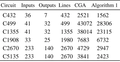
Table 1 The Results For ISCAS’85 Benchmark Circuits.
Circuit Inputs Outputs Lines CGA Algorithm 1
C432 36 7 432 2521 1562 C499 41 32 499 43072 28306 C1355 41 32 1355 38014 23115 C1908 33 25 1980 7683 6732 C2670 233 140 2670 4729 2947 C5135 233 140 2670 3841 2423
In the Table 1, the column “Circuit” shows the names of benchmark circuits. The columns “Inputs” and “Outputs” show the numbers of primary inputs and primary outputs in the circuits, respectively. The column “Lines” gives the total number of signal lines in a circuit. The columns “Algorithm 1” and “CGA” show the numbers of nodes in the BDDs obtained by the Algorithm 1 in this paper and by conventional genetic algorithm, respectively.
For the test vector of open faults, we randomly choose 50 open faults for every benchmark circuit, and use the Algorithm 3 in this paper to produce the test vectors. The variable orderings obtained by the Algorithm 1 is used to construct the BDDs of these circuits. The experimental results show that if there are test vectors for an open fault, then the test vectors can be produced by the Algorithm 3. The time of producing all test vectors of an open fault is less than one minute for all these benchmark circuits.
Summarize these experimental results, it is shown that the approach proposed in this paper can obtain the BDD with smaller number of nodes than conventional genetic algorithms. The test vectors of open faults can be produced if there are test vectors for the open faults.
6. CONCLUSIONS
The BDD can be used to represent the logic functions of digital circuits. The number of nodes in a BDD depends on the orderings of input variables. In this paper, a new approach based on chaotic evolution algorithm is presented for the variable ordering and the optimization of BDD, and the application of the approach for the test of stuck-open faults in digital circuits is given. One advantage of the approach is that all test vectors of an open fault can be obtained. Some work needs to
be done in the future such as investigating the features of the optimal variable ordering.
ACKNOWLEDGEMENTS
This work were supported by National Natural Science Foundation of China (No.61072028), the Project of Department of Education of Guangdong Province (No.2012KJCX 0040), Guangdong Province & Chinese Ministry of Education Cooperation Project of Industry, Education and Academy (No.2009B090300339).
REFRENCES:
[1] O.Keren, I.Levin, R.Stankovic. “Determining the number of paths in decision diagrams by using autocorrelation coefficients”. IEEE
Trans. on Computer-Aided Design of
Integrated Circuits and Systems, vol.30, no.1,
2011, pp.31-44.
[2] O.Lhotak, S.Curial, J.N.Amaral. “An optimal encoding to represent a single set in an ROBDD”. IEEE Trans. on Computers, vol.59, no.4, 2010, pp.574-575.
[3] J.A.Carrasco, V.Sune. “An ROBDD-based combinatorial method for the evaluation of yield of defect-tolerant systems-on-chip”. IEEE Trans. on Very Large Scale Integration (VLSI)
Systems, vol.17, no.2, 2009, pp.207-220.
[4] M.A.Kochte, S.Kundu, K.Miyase, W.Xiaoqing, H.Wunderlich. “Efficient BDD-based fault simulation in presence of unknown values”.
Proceedings of Asian Test Symposium, New
Delhi (India), November 20-23
,
2011, pp.383-388.[5] A.P.Ulmeanu. “Analytical method to determine uncertainty propagation in fault trees by means of binary decision diagrams”. IEEE Trans. on
Reliability, vol.61, no.1, 2012, pp.84-94.
[6] X.Liudong, O.Tannous, J.B.Dugan. “Reliability analysis of nonrepairable cold-standby systems using sequential binary decision diagrams”. IEEE Trans. on Systems,
Man and Cybernetics, Part A: Systems and
Humans, vol.42, no.3, 2012, pp.715-726.
[7] R.Ebendt, R.Drechsler. “Effect of improved lower bounds in dynamic BDD reordering”.
IEEE Trans. on Computer-Aided Design of
Integrated Circuits and Systems, vol.25, no.5,
[8] R.Ebendt, R.Drechsler. “Approximate BDD minimization by weighted A*”. IEEE International Symposium on Circuits and
Systems, Taipei (Taiwan), May 24-27, 2009,
pp.2974-2977.
[9] Z.Nevo, M.Farkash. “Distributed dynamic BDD reordering”. Proceedings of
Design Automation Conference, San Francisco
(USA), July 24-28, 2006, pp.223-228.
[10] C.Rotaru, O.Brudaru. “Multi-grid cellular genetic algorithm for optimizing variable ordering of ROBDDs”. Proceedings of IEEE
Congress on Evolutionary Computation,
Brisbane (Australia), June 10-15, 2012, pp.1-8.
[11] M.Yuchang. “Variable ordering to
improve BDD analysis of phased-mission systems with multimode failures”. IEEE Trans.
on Reliability, vol.58, no.1, 2009, pp.53-57.
[12] H.Iwasaki, S.I.Minato, T.Zeugmann. “A method of variable ordering for zero-suppressed binary decision diagrams in data mining applications”. Proceedings of IEEE International Workshop on Databases for Next
Generation Researchers, Istanbul (Turkey),
April 15-16, 2007, pp.85-90.
[13] F.Pareschi, G.Setti, R.Rovatti. “Implement-ation and testing of high-speed CMOS true random number generators based on chaotic systems”. IEEE Trans. on Circuits and Systems
I: Regular Papers, vol.57, no.12, 2010,
pp.3124-3137.
[14] C.K.Chow, S.Y.Yuen.
“An evolutionary algorithm that makes decision based on the entire previous search history”. IEEE Trans. on Evolutionary
Computation, vol.15, no.6, 2011, pp.741-769.
[15] A.Essalmi, H.Mahmoudi. “Neuro-genetic input-output linearization control of permanent magnet synchronous motor”. Journal of Theoretical and Applied Information
Technology, vol.37, no.1, 2012, pp.105-111.
[16] V.Champac, J.Hernandez, S.Barcelo,R.Gomez, C.Hawkins, J.Segura. “Testing of stuck-open faults in nanometer technologies”. IEEE
Design & Test of Computers, vol.29, no.4,