DEVELOPMENT OF A PROGRAM
FOR THE HYBRID SIMULATION OF A TUBULAR REACTOR ABSTRACT: The conceptual details of the hybrid solution of the
equations necessary for the study of the transient behavior of a
chemical tubular reactor are discussed in the following material. This behavior is considered under various conditions when an opti-mizing controller is installed. The analog and digital operations
available in the EAI HYDAC* system are utilized to advantage to solve the partial differential equations which describe the flow of reacting material down the length of the reactor.
The solutions to these equations are based on a function iteration scheme utilizing digital function storage to reduce the amount of analog non-linear equipment required through the time-sharing of analog operations. The advantages of analog simulation over purely numerical solutions are retained in evaluating the stability of the control scheme in this way.
TEMP. : Th
•
WALL TEMP.: e(x)REACTANT TEMP.: Tlx)
•
STATEMENT OF THE PROBLEM
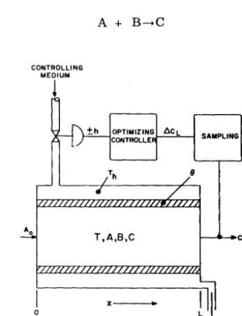
The problem used as a basis for discussion is con-cerned with the investigation of the control charac-teristics of a chemical reactor under various operating conditions for purposes of evaluating a particular optimizing control scheme. Major com-ponents of the physical system are shown in the block diagram of Figure 1.
A stream of reacting material flows through the reactor at a fixed velocity V. At the reactor input a feed of reactant A, with molar concentration Ao is introduced. Ao is, in general, a function of time t. Material A is assumed to undergo an intermedi-ate reaction.
[image:2.627.74.248.333.560.2]at a temperature dependent rate, R = f(T) , while the intermediate B reacts with A at a rate K, to produce a product C such that
Figure 1.
CONTROLLING MEDIUM
!
I
oOPTIMIZING 6CL CONTROLLE
T,A,B,C
x--_
SAMPLING
8
Block Diagram of Tubular Reactor with Optimizing Controller
It is desired to produce as much as possible of prod uct C. To thi s effect the temperature of the controlling medium Th can be adjusted to influence the reactor wall temperature () which, in turn, influences the temperature T of the reacting ma-terial and thus the reaction rate.
EQ UA TrONS based on material and heat balances can be written taking into consideration the follow-ing simplifyfollow-ing assumptions:
L Temperature Th is constant over the length of the reactor.
2. Temperature 8 has no axial diffusion.
3. Only convection and no diffusion take place in the reacting material.
Appropriate equations are:
~ -t V
oA
= -2RA2 -K ABat
ax
(1)o
B + Va
B = RA2 -K ABat
(}
x • (2)(}C + V iJ C
=
K AB() t 0 x (3)
iJT aT 2 ( )
a ( - -+ V - - ) = - b.RA + b2 8 - T
• 0 t
ax
(4)(5)
R
=
f(T) (6)(7)
x
=
L~C = CL (8)SOLUTION of the above differential equations allows an investigation of various control schemes based on the adjustment of one or more of the variables
Ao , To, Th as functions of the output concentration
CL. In order to predict the behavior of such con-trol arrangements, when installed on line, the slow transient response of the wall temperature 8 due to its large heat capacity has to be taken into ac-count (Eqn. 5). It is possible to solve equations (1) through (4) by following the passage of a fluid seg-ment through the reactor, but in order to account for the effect of the behavior of the wall tempera-ture some form of function storage is necessary.
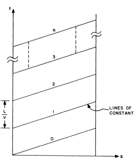
Referring to the diagram of Figure 2 the solution scheme chosen would be equivalent to solutions performed along the flow lines (concentration lines) which amounts to a change of independent variable. This new variable is defined as
t' = t x V
such that the flow lines now become lines of con-stant t. Performing the change in variable results in
_0_ + V _0_ being changed to V
-0
°
at
ox
xand
00 t being changed to : t I
*
A time delay of n samples must then be placed on C to obtain it in compatible time with the input.L
L
V
-L
LINES OF CONSTANT tl
~---~----~~x
o L
Figure 2. Plot of Flow Lines in Tubular Reactor
Thus, equations (1) through (4) are integrated at constant
t'
with x changing from 0 to L in one analog run. On the nth run, t' =t'n =nL/V. Equation (5) is approximated by the finite-difference expres-sion() (x) - 8 (x)
a
2 n L n-I = b (T - 8 ) z n n + b (T3 h n - 8 )(9) n
V
Both (In(x) and Th n
(x) are defined on a flow line
x=x
t = nL + x
V (10)
For () n this implies that the initial wall tempera-ture distribution, (J o (x) , be given on the n = 0 flow line. For Th it can be assumed, thanks to the slug-n gish response of the wall temperature, that Th is constant in x for constant t', or
Th = Th (t~) = Th (tn)
n
(11)
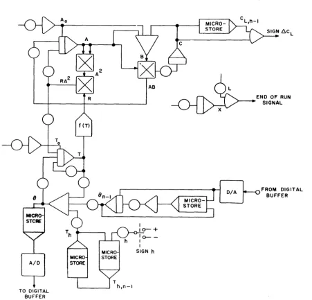
THE ANALOG PROGRAM, whose structure is shown in Figure 3, would then be required to solve the following equations (with run time proportional to x):
dAn 2
V - - = -2 RA -K A B
dx n n n
dB
V--n-=RA2_KAB
dx n nn
de
V-n-=KAB
dx nn
dT
a,V __ n_ = -bl RA2 + b
2 (8 -T )
dx n n n
a2V
- - (8 -L n 8 n-I )=b2(T n - 8 n )+b (T - 8 ) 3 h n
n
R
=
f(T ) n(12)
(13)
(14)
(15)
(16)
(17)
Note that A + 2B + 3C = Constant, which makes it possible to calculate B by
B = 1/2 (A - A - 3C )
n O n n (18)
n
where A = A (0), the input concentration
ofma-' 0 n
. A n
terIal (x = 0) at time t = t . At the end of an ana-n
[image:3.623.71.302.368.635.2]obtained at timet == tn +
~.
Cn is obtainedsimul-V
L
taneously in real time with Ao' n-II, Th, n+ 1 and and To' n+ 1 (the initial condition for Tn on the n+ 1 run).
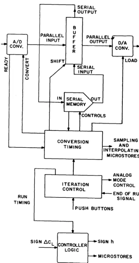
The function () n-l (x) obtained on the previous run is stored in the HYDAC memory. While it is being read out () n (x) is stored in its place for use in the following run. A function iteration is thus per-formed, an operation for which a standard "cook-book" program has been formulated. The structure of such a program is shown in Figure 4.
AID
TO DIGITAL
BUFFER
Tn this program the "iteration control" calls for successive analog runs and insures the timing for function storage. The converters communicate with the serial memory via a buffer. "Conversion tim-ing" calls for a complete cycle of sampling, A/D conversion, transfer to buffer, writing into the memory, reading out the memory, loading the D/ A conversion, and interpolating.
THE OPTIMIZING CONTROLLER attempts to max-irnize production of component C by acting on vari-able Th. It operates on successive samples of the output concentration C L taken at time intervals n
DIA
END OF RUN SIGNAL
FROM DIGITAL BUFFER
[image:4.618.65.517.242.676.2]L/V. The new sample is compared with the previ-ous one, and if an increase in C L is detected, Th is changed up or down by an amount h. When a de-crease in concentration is sensed a counter is advanced. When this counter carries out, indicating that This moved in the wrong direction, the direc-tion is reversed and the counter is cleared. Due to the system time lags between Th and CL this arrangement is extremely critical from the point of view of stability. This is what makes the analog simulation mandatory. Due to the non-linearity of the equations the transient behavior and stability of the system will depend on the values of the input
concentration
Ao
and temperature To which vary in time. The "stable" situation corresponds to a steady "hunting" oscillation across the maximum production point. In general, any optimizing con-troller must have such an oscillation since under entirely steady conditions it is impossible to know whether a higher yield can be obtained or not.A small number of digital logic building blocks are assembled to provide the logic for the controller. Their function is to switch Microstore components at every run and determine the sign of the correc-tion made to Th, Le., h •
. l.l
l
~~RIAL~UTPUT
AID
... CONV.
>-o
PARALLEL INPUT
SHIFT B U
F F
E
R
PARALLEL; OUTPUT DIA
CONV. ~ LOAD
~ W
0::
t-o::
w
>
z o
o
. J -_ _ - - - '
t
SERIAL INPUTRUN TIMING
I N SERIAL
~UT
L...--+_-..4I
MEMORY--1
CONTROLS
CONVERSION TIMING
r
ITERATION CONTROL
1
SAMPLING
f---+ AND INTERPOLATING
MICROSTORES
ANALOG
f---+ MODE CONTROL
i'---END OF RUN
L . . . - - - - T -_ _ _ _ _ ~ SIGNAL
1
PUSH BUTTONS1
SIGN 6C L CONTROLLER~SIGN h
LOGIC
[image:5.624.192.419.241.668.2]~ MICROSTORES
APPENDIX
The Serial Memory Units
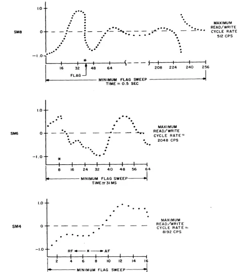
The Serial Memory Unit used to store 0n(x) in the function iteration program may be described as a device for storing a table of numbers, or digital "words", that represent a sequence of sampled values of an analog signal. All numbers are stored as serial binary words of 16 bits each. Each unit has its own control circuitry for writing, address-ing, and reading the tabular values in the proper sequence. Each size of memory unit (SM-B, SM-6, SM-4) has a different Read/Write Cycle Rate. This rate is the maximum number of data words per second that, in the normal mode of operation, can
U6-BIT SERIAL WORDS) __ DA~:r.~A,;...,.;..;.IN~---1~
RF
F
be written into and read from memory in sequence. Any lower rate may be used, as may be required by the analog-to-digital conversion rate or the analog sampling rate. The entire table of numbers can be read rapidly from memory in a single Read/ Write cycle, but, in normal use a single word is selected from the table and a new word written into the same position in one cycle, and the selected
po-sition is moved to the next in the sequence.
Figures 5 and 6 illustrate the characteristics of the Serial Memory units. The tables of data
.--I~"" (16 BITS SERIAL WORDS)
IN OUT IN OUT
(A) SERIAL MEMORY, SM8 (28 OR 256 WORDS OF STORAGE)
66 66
F
(B) SERIAL MEMORY, SM6 (26 OR 64 WORDS OF STORAGE)
(C) SERIAL MEMORY, SM4 (24 OR 16 WORDS OF STORAGE)
DATA IN
(0) MEMORY BUFFER ( I WORD OF STORAGE)
~o~
66
OIFil
A F R F AF R F
00 00
--PATCH PANEL LAYOUT
[image:6.613.190.326.627.684.2]words are addressed by a moving index' 'flag" . The flag is moved forward (left-to-right in Figure 6) one step each Read/Write Cycle during which the AF (advance flag) control line is energized. The flag may be moved in the reverse direction, one step per cycle, by the RF (reverse flag) control line. If
the AF line is energized all the time, the entire
table will be addressed at the maximum Read/ Write cycle rate (512 cps, 2048 cps, or 8192 cps) and thus the flag will sweep the entire function table in the minimum sweep time (0.5 sec., 31 millisec., or 2 millisec.). If the flag is moved be-yond the #256 position it steps to position #1, in the 8M-8.
SM8 SM6 SM4 1.0 o
...
. .
.
.
.
.
•
•
. .
•
•
.
.
....
-.:-
. .
:
.
...
-
---.-;.
.
. .
.
. .
.
..
.
.
.
.
..-.
...
~_
..
.
.
.
.
.
.
.
•
·
•
.
.
•
·
.
...
--! • • •..
- I .0 lL----·
.--+--~---r--+----1t----"'\
- , I
*
~- - -
5'---+----+----+----1I
16 FL::J 48
1.0 o -1.0 \.0 o -1.0 64
.... t - - - -
MINIMUM FLAG SWEEP TIME::. 0.5 SEC..
•
..
.
.
..
-.-*
•
...
.
.
... .
.
.
.
•
•
•
.
..
.
.
.
•
•
•
•
•
•
•
--.-.
.
•
..
I
8 16 24 32 40 48 56 64...
~t---
MINIMUM FLAG SWEEP----lTlME~31 MS
.
.
.
•
. .
. . .
R F + - - * - - ' A F
~ 2 4 6 8 10 12 14 16
"'~~----MINIMUM
FLAG SWEEP---...~~
TIME ~ 2 MS208 224 240 256
MAXIMUM READ/WRITE CYCLE RATE=
2048 CPS
MAXIMUM READ/wRITE
CYCLE RAT E
=-8192 CPS
J
Figure 6. Characteristics of Serial Memory Units
MAXIMUM READ/WRITE CYCLE RATE-=
[image:7.621.67.538.180.718.2]The tabular data words selected by the movingflag are "read out" by forming the logical product (with an AND gate) of the data output and the FD control lipe. The FD (flagged-data) line provides an enabling signal long enough to pass the serial bits
of
the indexed or flagged word, once each Read/Write cycle. Thus reading from the memory is possible without employing any specific "read" control signal.New data is written into the memory at the flagged position whenever the W control line is energized and the new serial data is available at the input.
The F (flags) control line permits the simultaneous use of as many as three independent flags in a Serial Memory Unit. Thus in special programs it is possible to move these flags back and forth inde-pendently to select the desired position for reading or writing. The L (load) control line is similar in function to the W line but is used to prestore or initialize the memory unit with special data, such as initial flag locations.
7
The range of memory sizes and maximum Read/ Write cycle rates satisfies a wide range of problem requirements. For transport delay programs the required minimum sampling rate and the delay time may determine the choice of memory unit. For function storage and generation the SM-8 unit will handle a 256-point function in as short a period as 0.5 second. Thus, for real time programs the SM-8 is very satisfactory; however, for high speed repetitive programs the SM-6 is better since it can be used with a time base as short as 31 millisec-onds. The SM-4 is useful mostly for very short delays, and with other units. It must be noted that function tables of any size can be programmed simply by cascading Serial Memory Units. If dif-ferent size units are employed the lowest maximum
Read/Write cycle rate applies to the combination. Many additional useful operations may be per-formed with these memory units together with logic building blocks and the analog computer. These are presented in other reports on the Serial Memory
Units for the analog computer.
EAI
®ELECTRONIC ASSOCIATES, INC. Long Branch, New Jersey