Active Filters
Hitesh B. Kapadiya
1Vinod S. Tejwani
2Dipak. G. Parmar
31,2,3
Lecturer
1,2,3
Government Polytechnic, Ahmedabad, Gujarat, India
Abstract— Active power filter continues to attract
considerable attention. Because of sensitivity of consumers on power quality and advancement in power electronics. Active power filter technology is the most efficient way to compensate reactive power and cancel out low order harmonics generated by nonlinear loads. An active power filter is a device that is connected in parallel to and cancels the reactive and harmonic currents from the group of nonlinear loads so that the resulting total current drawn from the ac main is sinusoidal. The shunt active power filter was considered to be the most basic configuration for the APF. This project presents 3phase shunt active power filter with uni-polar pulse width modulation technique to make the total input current drawn from the three phase AC main as sinusoidal, by compensating reactive power And low order harmonics generated by the three phase nonlinear loads. The synchronous d-q-o reference frame algorithm is also used to recognize and extract harmonic distortions. The validity of proposed method and achievement of desired compensation are shown by simulation results.
Key words: Active Filters
I. INTRODUCTION
A. Problem Summery
Early equipment was designed to withstand disturbances such as lightning, short circuits, and sudden overloads without extra expenditure. Current power electronics (PE) prices would be much higher if the equipment was designed with the same robustness.
Approximately 10% to 20% of today’s energy is processed by PE; the percentage is estimated to reach 50% to 60% by the year 2010, due mainly to the fast growth of PE capability.
Increase in such non-linearity causes different undesirable features like low system efficiency and poor power factor. It also causes disturbance to other consumers and interference in nearby communication networks. The effect of such non-linearity may become sizeable over the next few years. Hence it is very important to overcome these undesirable features. Classically, shunt passive filters, consist of tuned LC
filters and/or high passive filters are used to suppress the harmonics and power capacitors are employed to improve the power factor. But they have the limitations of fixed compensation, large size and can also exile resonance conditions.
Active power filters are now seen as a viable alternative over the classical passive filters, to compensate harmonics and reactive power requirement of the non-linear loads. The objective of the active filtering is to solve these problems by combining with a much-reduced rating of the necessary passive components.
Mainly the Harmonics Components, especially Low Ordered Harmonics affects the performances of electrical lines and most the power quality. For eliminate this worst effects of Harmonics, now a day’s the Shunt Active Falter is widely in use.
B. What Is Power Quality..?
The PQ issue is defined as “any occurrence manifested in voltage, current, or frequency deviations that results in damage, upset, failure, or disoperation of end-use equipment.”
Almost all PQ issues are closely related with PE in almost every aspect of commercial, domestic, and industrial application.
Equipment using power electronic devise are residential appliances like TVs, PCs etc. business and office equipment like copiers, printers etc. industrial equipment like programmable logic controllers (PLCs), adjustable speed drives (ASDs), rectifiers, inverters, CNC tools and so on.
The Power Quality (PQ) problem can be detected from one of the following several symptoms depending on the type of issue involved.
1) Lamp flicker 2) Frequent blackouts
3) Sensitive-equipment frequent dropouts 4) Voltage to ground in unexpected 5) Locations
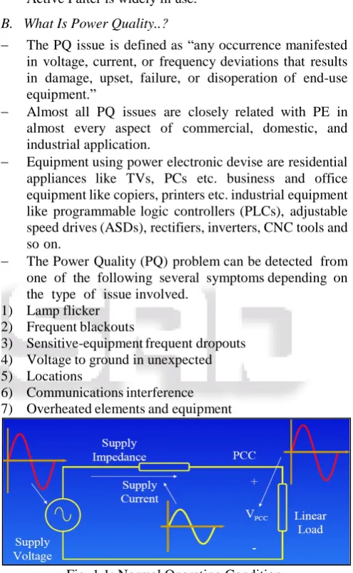
[image:1.595.306.554.180.582.2]6) Communications interference 7) Overheated elements and equipment
Fig. 1.1: Normal Operating Condition
C. Solution to Power Quality Problems
There are two approaches to the mitigation of power quality problems:
The first approach is called load conditioning, which ensures that the equipment is made less sensitive to power disturbances, allowing the operation even under significant voltage distortion.
The other solution is to install line-conditioning systems that suppress or counteract the power system disturbances.
harmonics, and they can introduce resonance in the power system.
Among the different new technical options available to improve power quality, active power filters have proved to be an important and flexible alternative to compensate for current and voltage disturbances in power distribution systems.
The idea of active filters is relatively old, but their practical development was made possible with the new improvements in power electronics and microcomputer control strategies as well as with cost reduction in electronic (Harmonics) components.
Active power filters are becoming a viable alternative to passive filters and are gaining market share speedily as their cost becomes competitive with the passive variety.
Through power electronics, the active filter introduces current or voltage components, which cancel the harmonic components of the nonlinear loads or supply lines, respectively. Different active power filters topologies have been introduced and many of them are already available in the market.
D. Power System Topologies
Depending on the particular application or electrical problem to be solved, active power filters can be implemented as shunt type, series type, or a combination of shunt and series active filters (shunt-series type). These filters can also be combined with passive filters to
create hybrid power filters.
The shunt-connected active power filter, with a self-controlled dc bus, has a topology similar to that of a static compensator (STATCOM) used for reactive power compensation in power transmission systems.
Shunt active power filters compensate load current harmonics by injecting equal-but opposite harmonic compensating current. In this case the shunt active power filter operates as a current source injecting the harmonic components generated by the load but phase-shifted by 180°.
Hybrid power filters are a combination of active and passive filters. With this topology the passive filters have dynamic low impedance for current harmonics at the load side, increasing their bandwidth operation and improving their performance.
This behavior is reached with only a small power rating PWM inverter, which acts as an active filter in series with the passive filter. Multilevel inverters are being investigated and recently used for active filter topologies.
Three-level inverters are becoming very popular today for most inverter applications, such as machine drives and power factor compensators.
II. HARMONICS
A. Types of Disturbance
[image:2.595.308.545.110.367.2]Here there are few types of Electric Disturbance is shown.
Fig. 2.1: Types of Disturbance
B. Harmonics
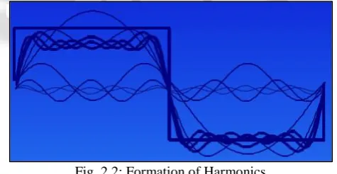
Every load today is capable of creating harmonics with the exception of the incandescent light bulb. But, the harmonic content varies from load to load and each load responds to the effects of harmonics.
Fig. 2.2: Formation of Harmonics
Harmonics became a buzzword in the early 1980s, making many people reassessed the effectiveness of their building's wiring system. Yet, many still view the concept as a relatively new occurrence.
However, harmonics have been there since well before the early '80s.The associated problems existed in the electrical system way back when transistor tubes were first used in the 1930s.
Aside from grounding, many consider harmonics as one of the biggest concerns for the power quality industry today. In this chapter, we'll discourse the fundamentals of harmonics and the problems it can cause in a power system.
C. What Are Harmonics?
[image:2.595.308.546.432.555.2]is 50 Hz. Therefore, harmonic order is 100 Hz, 150 Hz, and 200 Hz and so on.
We usually specify these orders by their harmonic number or multiple of the fundamental frequency. For example, a harmonic with a frequency of 150 Hz is
known as the third harmonic (50x3 = 150). In this case, for each cycle of the fundamental waveform, there are three complete cycles of the harmonic waveforms. The even multiples of the fundamental frequency are
called as even-order harmonics while the odd multiples are called as the odd-order harmonics.
D. Creation of Harmonics
Up until 1980, all loads were considered to be linear. This means if the voltage input to a device is a sinusoidal wave, the resultant voltage waveform generated by the load is also a sinusoidal wave.
In 1981, manufacturers of electronic hardware switched to an efficient type of internal power supply known as a switch-mode power supply (SMPS). The SMPS converts the applied voltage sine wave to a 4 distorted current waveform that resembles alternating current pulses, the original since the load no more exhibit constant impedance throughout the applied AC voltage waveform.
Most electrical equipment today creates harmonics. If a device converts AC power to DC power (or vice versa) as part of its steady-state operation, it is considered to be a harmonic current-generating device. Such devices include uninterruptible power supplies, copiers, PCs, etc.
E. Effects of Harmonics
The biggest problem with harmonics is voltage waveform distortion.
We can calculate a relationship between the fundamental and distorted waveforms by finding the square root of the sum of the squares of all harmonics generated by a single load, and then dividing this number by the nominal 50 Hz waveform value.
We do this by a mathematical calculation known as a Fast Fourier Transform (FFT) Theorem. This calculation method determines the Total Harmonic Distortion (THD) contained within a nonlinear current or voltage waveform.
1) Triplen Harmonics
Electronic equipment generates more than one harmonic frequency. For example, computers generate 3rd, 9th, and 15th harmonics.
These are known as triplen harmonics. They pose a bigger problem to engineers and building designers because they do more than distort voltage waveforms. They can overheat the building wiring, cause nuisance tripping, overheat transformer units, and cause random end-user equipment failure.
2) Circuit Overloading
Harmonics cause overloading of conductors and transformers and overheating of utilization equipment, such as motors.
Triplen harmonics can especially cause overheating of neutral conductors on 3-phase, 4-wire systems. While the
fundamental frequency and even harmonics cancel out in the neutral conductor, odd-order harmonics are additive. Even under balanced load conditions, neutral currents can reach magnitudes as high as 1.73 times the average phase current.
This additional loading creates more heat, which breaks down the insulation of the neutral conductor.
In certain cases, it breaks down the insulation between windings of a transformer.
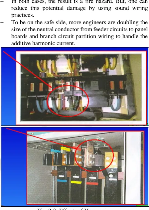
In both cases, the result is a fire hazard. But, one can reduce this potential damage by using sound wiring practices.
To be on the safe side, more engineers are doubling the size of the neutral conductor from feeder circuits to panel boards and branch circuit partition wiring to handle the additive harmonic current.
[image:3.595.306.552.178.525.2]
Fig. 2.3: Effects of Harmonics
F. Methods of Elimination of Harmonics
Four of the most recommended solutions include: 1) Increasing the size of the neutral conductor 2) Decreasing the load of delta-wye transformer
3) Replacing the delta-wye transformer with a k-factor transformer
4) Installing a harmonic filter at the power source or equipment location.
The first three solutions help us cope with the problem; the fourth actually eliminates the problem.
G. Harmonic Filters
A harmonic filter can eliminate the potentially dangerous effects of harmonic currents created by nonlinear loads. It traps these currents and, through the use of a series of
capacitors, coils, and resistors, shunts them to ground. A filter unit may contain several of these elements, each
We can install filters either between the device we are trying to protect and the load's power source, or between the device causing the condition and its power source. There are two types of harmonic filters:
1) Passive Filter 2) Active Filter 1) Passive Filters
These are inexpensive compared with most mitigating devices. Internally, they cause the harmonic current to resonate at its frequency. This prevents the harmonic current from flowing back to the power source and causing problems with the voltage waveform. A disadvantage of the passive filter is that it cannot be perfectly tuned to handle the harmonic current at a significant frequency.
2) Active Filters
These filters, on the other hand, can be tuned to the exact frequency of the harmonic current and do not cause resonance in the electrical system.
They can also address more than one harmonic problem at the same time. Active filters can also provide mitigation for other power quality 7 problems such as voltage sags and power line flicker.
They use power electronics to replace part of the distorted current sine wave coming from the load, giving the appearance you're using only linear loads. As a result, the active filter provides power factor correction, which increases the efficiency of the load.
H. Determination of Presence of Harmonic Currents
If non-linear loads are a significant part of the total load in the facility (>20%), there is a chance of harmonics problem. So the amount of current produced by non-linear loads is calculated by calculating the THD. Electronic Ballasts come with current THD ranging from
60% to 100%. It is absolutely necessary to avoid electronic ballasts with more than 20% THD. Near to 100% THD is produced by PWM ASDs. This can be easily brought down to less than half by installing cheap 3% impedance line side reactors (chokes).
A measurement of current in the neutral of a 3-phase 4-wire system gives us knowledge about the presence of harmonics. If neutral current is found substantially higher than the imbalance from the imbalance in the 3-phase currents, it can be safely assumed that there are harmonics present in the system.
Another very important sign of presence of current harmonics in the system include inexplicable higher than normal temperatures in the transformer, voltage distortion and high crest factor.
Fig. 2.4: Different THD in Home Appliance
III. SHUNT ACTIVE POWER FILTER
A. Introduction
The shunt-connected active power filter, with a self-controlled dc bus, has a topology similar to that of a static compensator (STATCOM) used for reactive power compensation in power transmission systems.
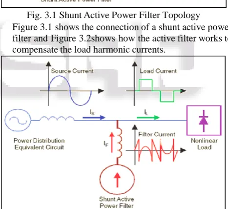
Shunt active power filters compensate load current harmonics by injecting equal-but opposite harmonic compensating current.
[image:4.595.297.549.105.581.2] In this case the shunt active power filter operates as a current source injecting the harmonic components generated by the load but phase-shifted by 180°.
Fig. 3.1 Shunt Active Power Filter Topology Figure 3.1 shows the connection of a shunt active power
filter and Figure 3.2shows how the active filter works to compensate the load harmonic currents.
Fig. 3.2. Filter Current IF Generated To Compensate Load-Current Harmonic
B. Basic Compensation Principle
Figure 3.3. Shows the basic compensation principle of a shunt active power filter.
It is controlled to draw / supply a compensating current ic from / to the utility, so that it cancels current harmonics on the AC side, and makes the source current in phase with the source voltage.
Figure.3.4. shows the different waveforms.
[image:4.595.312.546.363.577.2] [image:4.595.60.278.637.756.2]Fig. 3.3: Shunt Active Power Filter Basic Compensation Principle
Fig. 3.4: Shunt Active Power Filter-Shapes of Load, Source and Desired Filter Current Waveforms
C. Estimation of Reference Source Current
The peak value of the reference current Isp can be estimated by controlling the DC side capacitor voltage. Ideal compensation requires the mains current to be sinusoidal and in phase with the source voltage, irrespective of the load current nature. The desired source currents, after compensation, can be given as
isa = I sp sin ω t isb=Isp sin(ωt − 120
° )
isc=Isp sin(ωt + 120°)
Where Isp(=I1cosΦ1+Isl) the amplitude of the desired source current, while the phase angle can be obtained from the source voltages. Hence, the waveform and phases of the source currents are known, and only the magnitudes of the source currents need to be determined. This peak value of the reference current has been estimated by regulating the DC side capacitor voltage of the PWM converter. This capacitor voltage is compared with a reference value and the error is processed in a fuzzy controller. The output of the fuzzy controller has been considered as the amplitude of the desired source current, and the reference currents are estimated by multiplying this peak value with unit sine vectors in phase with the source voltages [6].
D. Role of DC Side Capacitor
The DC side capacitor serves two main purposes: (i) it maintains a DC voltage with small ripple in steady state, and (ii) serves as an energy storage element to supply real power difference between load and source during the transient period. In the steady state, the real power supplied by the source should be equal to the real power demand of the load plus a small power to compensate the losses in the active filter. Thus, the DC capacitor voltage can be maintained at a reference value.
However, when the load condition changes the real power balance between the mains and the load will be disturbed. This real power difference is to be compensated by the DC capacitor. This changes the DC capacitor voltage away from the reference voltage. In order to keep satisfactory operation or the active filter, the peak value of the reference current must be adjusted to proportionally change the real power drawn from the source. This real power charged/discharged by the capacitor compensates the real power consumed by the load. If the DC capacitor voltage is recovered and attains the reference voltage, the real power supplied by the source is supposed to be equal to that consumed by the load again.
Thus, in this fashion the peak value or the reference source current can be obtained by regulating the average voltage of the DC capacitor. A smaller DC capacitor voltage than the reference voltage means that the real power supplied by the source is not enough to supply the load demand. Therefore, the source current (i.e. the real power drawn from the source) needs to be increased, while a larger DC capacitor voltage than the reference voltage tries to decrease the reference source current. This change in capacitor voltage has been verified from the simulation results.
The real/reactive power injection may result in the ripple voltage of the DC capacitor. A low pass filter is generally used to filter these ripples, which introduce a finite delay. To avoid the use of this low pass filter the capacitor voltage is sampled at the zero crossing of the source voltage. A continuously changing reference current makes the compensation non- instantaneous during transient. Hence, this voltage is sampled at the zero crossing of one of the phase voltage, which makes the compensation instantaneous. Sampling only twice in cycle as compared to six times in a cycle leads to a slightly higher DC capacitor voltage rise/dip during transients, but settling time is less.
The design of the power circuit includes three main parameters:
Selection of filter inductor, Lc. Selection of DC side capacitor, Cdc.
Selection of reference value of DC side capacitor voltage, Vdc,ref.
IV. SIMULATION RESULTS
RATING ARE GIVEN IN BELOW TABLE: Sr
1 3 Phase Supply
1. Supply Voltage 2. Frequency
1. 400v 2. 50hz
2 Rectifier Unit(Load)
1. Step Time 2. Initial Value
3. Final Value
A. 5/60 B. 2000 C. 3000 Table 1:
A. Power System with Resistive Load
[image:6.595.43.291.63.303.2]1) Without Active Filter
Fig. 4.1 Model of POWER SYSTEM with R Load in MATLAB without Active Filter
Now we can see the above model of a 3 phase supply through a rectifying unit with Resistive load and without active filter. Now below figure shows 3 phase supply circuit which gives 3 phase power supply to whole model.
Fig. 4.2 3-Phase Supply
[image:6.595.303.554.63.316.2]The below figure shows the rectifier unit. This unit has resistive load and have two output voltages.
Fig. 4.3 Rectifier Unit
From above figure we can clearly see that there are two output voltages. The simulation results of this model of without active filter are as follows.
[image:6.595.44.555.69.589.2]The below graph is for voltage at 1 which is dc and is denoted by Vdc1.
[image:6.595.298.553.342.579.2]Fig. 4.4: Voltage Graph of VS1 in Rectifier Unit The below graph is for voltage source 2 in rectifier unit which is denoted as Vdc2.
Fig. 4.5: Voltage Graph of VS2 in Rectifier Unit Now we can see supply current in form of graph of 3 phase supply.
Fig. 4.6: Supply Current Graph for load current
Fig. 4.7: Load Current
Here we can see from above both current graph that there is no change in supply current and load current. They have same harmonic level. From below figure analysis we can know THD value of system.
[image:6.595.46.300.359.486.2] [image:6.595.45.292.511.675.2]Fig. 4.8: THD Value
Here we are calculating from 3rd cycle for proper and accurate value. Frequency is of 50Hz. From this we came to know THD value.
[image:7.595.306.556.85.354.2]2) With Active Filter
Fig. 4.9: Model of Power System with R Load In Matlab with Active Filter
In above figure we can see there is a 3 Phase supply, Filter unit and load unit. The filter unit is in between supply and load unit.
The below figure shows Filter Unit.
Fig. 4.10: Active Filter Unit
In figure we can see PLL which is used for measuring frequency and to reduce change in frequency a pulse giving from IGBT based inverter. This inverter is connected with two capacitors.
The circuit figure of 3 Phase supply and a Rectifier Units are same as above.
The simulation results of this model of with active filter are as follows.
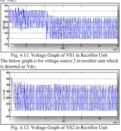
The below graph is for voltage at 1 which is dc and is denoted by Vdc1.
Fig. 4.11: Voltage Graph of VS1 in Rectifier Unit The below graph is for voltage source 2 in rectifier unit which is denoted as Vdc2.
[image:7.595.250.548.151.646.2]Fig. 4.12: Voltage Graph of VS2 in Rectifier Unit Now we can see supply current in form of graph of 3 phase supply.
Fig. 4.13: Supply Current Graph for load current
Fig. 4.14: Load Current
From above graph we can see that there is difference in currents of load and suppl. This is due to filter unit kept between them. They have some harmonic which is removed. From below figure analysis we can know THD value of system.
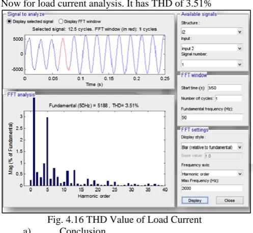
[image:7.595.46.297.288.656.2] [image:7.595.304.554.356.642.2]Fig. 4.15: THD Value of Supply Current This analysis for supply current. It has THD of 5.27% Now for load current analysis. It has THD of 3.51%
Fig. 4.16 THD Value of Load Current a) Conclusion
From above simulation analysis we came to know that by keeping active filter there is reduce in harmonic in resistive load.
B. Power System with R-L Load
[image:8.595.305.554.87.553.2]1) Without Active Filter
Fig. 4.17: Model of Power System with RL Load in MATLAB without Active Filter
Now we can see the above model of a 3 phase supply through a rectifying unit with RL load and without active filter.
Now below figure shows 3 phase supply circuit which gives 3 phase power supply to whole model.
Fig. 4.18: 3 Phase Supply 2) Figure of Load
Fig. 4.19: Load Unit The below figure is RL load Unit.
Fig. 4.20: Rectifier Unit
3) Graph of Supply Voltage
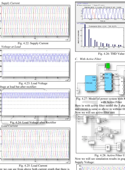
[image:8.595.44.293.291.520.2] [image:8.595.45.292.565.718.2]4) Supply Current
Fig. 4.22: Supply Current 5) Voltage at Load
Fig. 4.23: Load Voltage Voltage at load but after rectifier:
Fig. 4.24: Load Voltage after Rectifier
6) Load Current
Fig. 4.25: Load Current
Here we can see from above both current graph that there is no change in supply current and load current. They have same harmonic level. From below figure analysis we can know THD value of system.
[image:9.595.298.551.68.693.2]Harmonic order of current is 20.67% as shown in below figure.
Fig. 4.26: THD Value
C. With Active Filter
Fig. 4.27: Model of power system with RL Load in matlab with Active Filter
Here in with active filter model the 3 phase supply and load unit circuit is same as above in without filter model.
Now we will see active filter unit
Fig. 4.28: Active Filter Unit Now we will see simulation results in graphs: Supply Voltage:
1) Supply Current
Fig. 4.30: Supply Current 2) Voltage at Load
Fig. 4.31: Load Voltage 3) Voltage at Load after Rectifier Unit
Fig. 4.32: Load Voltage after Rectifier Unit
4) Load Current
Fig. 4.33: Load Current
From above graph we can see that there is difference in currents of load and suppl. This is due to filter unit kept between them. They have some harmonic which is removed. From below figure analysis we can know THD value of system.
[image:10.595.310.550.70.266.2]Here we are calculating from 3rd cycle for proper and accurate value. Frequency is of 50Hz. From this we came to know THD value.
[image:10.595.309.549.118.499.2]Fig. 4.34: THD Value of Supply Current This analysis for supply current. It has THD of 20.68%. Now for load current analysis. It has THD of 9.19%.
Fig. 4.35: THD Value of Load Current
V. CONCLUSION
From above simulation analysis we came to know that by keeping active filter there is reduce in harmonic in RL load.
REFERENCES
[1] W. M. Grady, M. J. Samotyj, and A. H. Noyola, “Survey of active power line conditioning methodologies,” IEEE Transactions on Power Delivery, vol. 5, no. 3,Jul. 1990, pp. 1536–1542.
[2] H. Akagi, Y. Kanazawa, and A. Nabae, “Instantaneous reactive power compensators comprising switching devices without energy storage components,” IEEE Transactions on Industry Applications, vol. IA-20, no. 3, May/Jun. 1984, pp. 625–630.
[3] S. Jain, P. Agarwal, and H. O. Gupta, “Design simulation and experimental investigations on a shunt active power filter for harmonics and reactive power compensation,” Electrical Power Components and Systems, vol. 32, no. 7, Jul. 2003, pp. 671–692.
converters for harmonic compensation,” IEEE Transactions on Power Electronics, vol. 5, no. 1, Jan. 1990, pp. 9–15.
[5] H.Akagi, “Trends in active power line conditioners,” IEEE Transactions on power Electronics, vol 9, no 3, 1994, pp 263-268.
[6] S. K. Jain, P. Agrawal, and H. O. Gupta, “Fuzzy logic controlled shunt active power filter for power quality improvement,” Proceedings of Institute of Electrical Engineers, Electrical Power Applications, vol. 149, no. 5, 2002.
[7] L.A.Morgan, J.W.Dixon & R.R.Wallace, “A three phase active power filter operating with fixed switching frequency for reactive power and current harmonics compensation,” IEEE Transactions on Industrial Electronics, vol.42, no.4, August 1995, pp 402-408. [8] B. Singh, A. Chandra, and K. Al-Haddad,
“Computer-aided modeling and simulation of active power filters,” Electrical Machines and Power Systems, vol. 27, 1999, pp. 1227–1241.
[9] B. Singh, A. Chandra, and K. Al-Haddad, “A review of active filters for power quality improvement,” IEEE Transactions on Industrial Electronics, vol.46, no 5, Oct 1999, pp1-12.
[10]R. M. Duke and S. D. Round, “The steady state performance of a controlled current active filter,” IEEE Transactions on Power Electronics, vol. 8, Apr. 1993, pp. 140–146.
[11]J.W.Dixon, J.J.Garcia & L.Morgan, “Control system for three phase active power filter which simultaneously compensates power factor and unbalanced loads,” IEEE Transactions on Industrial Electronics, vol.42, no.6, 1995, pp636-641.
[12]E.H.Watanbe, R.M.Stephan & M.Aredes, “New concepts of instantaneous active and reactive powers in electrical systems with generic loads,” IEEE Transactions on Power Delivery, vol.8, no.2, April 1993, pp.697-703.
[13]K. Chatterjee, B. G. Fernandes, and G. K. Dubey, “An instantaneous reactive volt-ampere compensator and harmonic suppressor system,” IEEE Transactions on Power Electronics, vol. 14, no. 2, Mar. 1999, pp. 381– 392.
[14]Shyh-Jier Huang and Jinn-Chang Wu, "A control algorithm for three-phase threewired active power filters under nonideal mains voltages," IEEE Transactions on Power Electronics, Vol. 14, No. 4, July 1999, pp 753-760.
[15]D.A.Torey& A.M..Al-Zamel, “A single phase active filter for multiple nonlinear load,” IEEE Transactions on Power Electronics, vol.10, May 1995, pp.263-272. [16]B. Singh, A. Chandra, and K. Al-Haddad, “Performance
comparison of two current control techniques applied to an active filter,”8th International conference on Harmonics and Power Qulaity ICHQP, Oct 1998, pp.133-138.
[17]Mohan, N., Undeland,.T.M, and Robbins,.W.P, “Power electronics :converters, applications and design,” Singapore,John Wiley and sons, 2003.
[18]B. K. Bose, “Modern Power Electronics and AC Drives,” Singapore, Pearson Education, 2004.
[19]Murphy and F.G. Turnbull, “Power Electronic Control of AC Motors”, Pergamon Press, Elmsford, New York, 1988
[20]Industrial and Commercial Power Systems Analysis, ANSI/IEEE Std. 3991990, Chapter 10.
[21]Electric Power Distribution for Industrial Plants, ANSI/IEEE Std. 141-1986, Chapter 8.
[22]IEEE Recommended Practices and Requirements for Harmonic Control in Electrical Power Systems, ANSI/IEEE Std. 519-1992.
[23]John F. Hibbard and Michael Z. Lowenstein, “Meeting IEEE 519-1992 Harmonic Limits”, TCI (Trans Coil, Inc.), 1993
[24]“In Tune with Power Harmonics”, John Fluke Mfg. Co., Inc., 1991 Ed Palko, “Living with Power System Harmonics”, Plant Engineering, June 18, 1992, pages 48-53.