Survey on Different Shape Microstrip Antenna with Different Slots
Prof. Neenansha Jain
1Shikha Verma
21
Assistant Professor
2M.Tech Student
1,2
Department of Electronics & Communication Engineering
1
RGPV, Bhopal
2Sagar Institute of Research, Technology and Science, Bhopal, Madhya Pradesh India
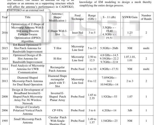
Abstract—In this survey paper discuss the different shape of microstrip patch antenna or different slots. In the last decade different shape based antenna proposed. In the current scenario for the improvement of result parameters using different slot in patch. Currently Giga hertz range 1 to 10 GHz and different band at C, K, Ku, Ka based design are hot topic in between researches. In this survey paper also compared the different slots and different antenna that is shown in table 1. In this survey, compared the different antenna on the basis of different result parameter shape of antenna, type of feed, frequency range, Return loss (S11), Voltage Standing Wave ratio (VSWR), Gain, Number of band.
Key words: Micro strip patch antenna, shape of antenna, type of feed, frequency range, return loss, VSWR, Gain, Number of band
I. INTRODUCTION
An antenna is a specialized transducer that converts radio-frequency (RF) fields into alternating current (AC) or vice-versa. There are two basic types: the receiving antenna, which intercepts RF energy and delivers AC to electronic equipment, and the transmitting antenna, which is fed with AC from electronic equipment and generates an RF field.
Low profile antennas are essential for many wireless and telecommunication systems and hand held mobile devices, where size, weight, cost, performance are constrained. They commonly consist of a rectangular or square metal patch on a thin layer of dielectric or substrate on a ground plane. The bandwidth specification of antennas should be satisfied for VSWR, radiation pattern and polarization properties.
Microstrip antenna is more attracted because of its size, weight, profile is in small order as well as easier to fabricate. Microstrip antennas have attracted more interest in satellite and wireless mobile communication [1, 2]. Broadband applications have been achieved by changing the shape and creating the slots in the design of the antenna. Requirements of the multi frequency band in wireless communication enrich its research. If a single small device can work in various frequency bands it helps to reduce the size, weight and circuitry [3, 4]. This boosts the researchers to work in this area. Similarly the feed of the antenna is an important aspect. In many ways it can be fed to the antenna.
Microstrip patch antennas are increasingly finding their applications in a broad range of microwave systems from radars, telemetry, navigation, biomedical systems, mobile and
Satellite communications, GPS (global positioning system) for remote sensing and etc. In case of contact based power is fed directly to the radiating patch, whereas in the non-contact case electromagnetic field requires coupling to transfer the RF power. Out of four popular contact based
feed, we have considered the microstrip line feed, since non-contact based feed is somewhat complex.
II. MICROSTRIP ANTENNA
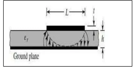
[image:1.595.299.531.362.493.2]In a most basic form a microstrip antenna comprises of two thin metallic layers (t˂˂λ0, whereλ0 is wavelength in free space) one as radiating patch and second as ground plane and a dielectric substrate sandwiched between them. The conductor patch is placed on the dielectric substrate and used as radiating element. On the other side of the substrate there is a conductive layer used as ground plane. Copper and gold is used normally as a metallic layer. Radiating patch can be of any shape but simple shapes are used to design a patch because patches basic shapes are easy to analysis by the available theoretical models and it is easy to predict the performance. Square, rectangular, dipole, triangular, elliptical, circular are some basic shapes. Circular, rectangular and dipole are the most often used shapes because of easy of analysis and fabrication.
Fig. 2.1: Microstrip Patch Antenna
A variety of dielectric materials are available for the substrate with dielectric constants 2.2≤εr≥12 [8]. The height of substrate plays an important role in antenna characteristics generally are in the range 0.003λ0 ≤h ≥ 0.05λ0.
[image:1.595.319.535.556.665.2]III. LITRATURE SURVEY
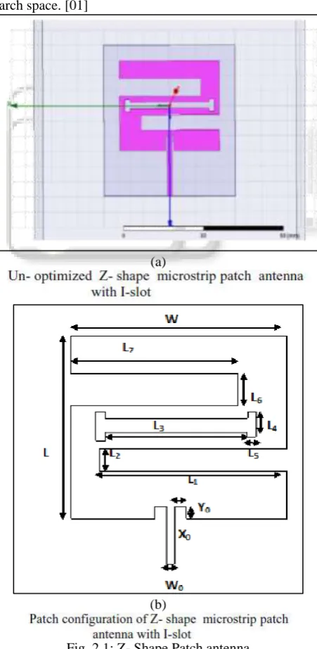
A. Swarnaprava Sahoo, et al. (2016), “Optimization of Z-Shape Microstrip Antenna with I- slot Using Discrete Particle Swarm Optimization (DPSO) Algorithm”
Summary- In this paper, discrete particle swarm optimization technique has been utilized in HFSS software for optimization of the Z-shape patch antenna with I- slot dimensions in order to achieve return loss, VSWR, directivity and gain. The designed antenna is to operate in Wi-Max / S- band and C- band satellite application with the center frequency at 3.5 GHz and 4.3 GHz and various important performance metrics of the patch antenna are analyzed for performing comparative analysis between un-optimized patch antenna and un-optimized patch design. The main point of the paper is to examine the suitability of discrete particle swarm optimization algorithm for antenna parameter optimization to achieve the better overall performance of the antenna. DPSO is general-purpose optimizer well suited for conducting search within a discrete search space. [01]
(a)
[image:2.595.54.280.297.759.2](b)
Fig. 2.1: Z- Shape Patch antenna
B. Anindita Das, et al. (2015), “EA Based Optimized T-Slot Patch Antenna for Bandwidth Improvement”
Summary- Microstrip antenna is a vital component of modern wireless communication systems. Therefore it requires optimized design for improving the overall performance of the system. The advancement of wireless devices including mobile equipments is ever growing area towards implementation. In this field importance of the antenna technologies grow accordingly. As handsets improve in compactness with multi functions in recent age, the antennas for these equipments have come under the spotlight. In this paper, the designing and analysis of T-slot microstrip patch antenna are presented. The shape will provide the broad bandwidth which is required for the operation of next generation wireless systems. Evolutionary Algorithm based optimization has been utilized in HFSSANSOFT to optimize the microstrip line feed antenna dimensions in order to obtain reliable return loss and high directivity. The operating frequency of antenna is 7GHz, the dielectric constant and thickness of the antenna is 4.4 and 1.6mm respectively. The simulation results of antenna are done by the help of HFSS and MATLAB programming. The microstrip patch antenna is designed with different centre frequencies such as 5.5GHz, 11.25GHz and 12.25GHz. The patch antenna is analyzed for different metrics for performance. A comparative analysis between non-optimized patch design and non-optimized patch design has also been presented. [03]
Fig. 2.2: T-slot microstrip patch antenna design.
C. Anindita Das, et al. (2015), “Optimized Design of H-Slot Antenna for Bandwidth Improvement”
[image:2.595.310.544.386.550.2]Fig. 2.3: H-slot patch antenna.
D. Shaktijeet Mahapatra, et al. (2014), “Feed Analysis of Microstrip Antenna for UWB Communication”
[image:3.595.305.543.148.488.2]Summary- In current trend, modern wireless technologies are being implemented with Wi-Fi technology. The technology makes it possible for the user to connect to the internet though wireless connection. That makes the wide use of Microstrip Patch Antennas in various applications, due to their low profile, conformability, easy realization. In this paper, an attempt has been made to design the Feed of Microstrip antenna structure and analyse for UWB Wireless application using Ansoft-HFSSv13. This is mostly due to their versatility in terms of possible geometries which makes these applicable for different situations. This antenna has a low profile configuration with excellent radiation pattern. Compared to the centre-fed patch antenna (CPA), the proposed antenna has a large bandwidth and similar radiation pattern. It has been tested for Centre-fed Rectangular Patch Antenna as well as Probe-fed Rectangular Patch Antenna. The result shows its efficiency. [06]
Fig. 2.4: centre fed rectangular patch antenna.
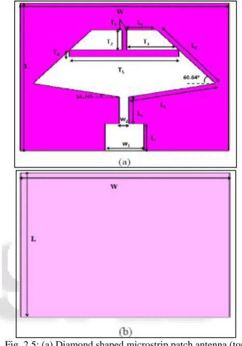
E. Ratnesh Kumari, et al. (2013), “Diamond shaped Microstrip patch antenna for Dual Band Operation” Summary- This paper proposes a compact sized Dual-band microstrip patch antenna with microstrip feeding line. The microstrip patch of the antenna is a diamond shaped patch which has a T-slot in the patch for the multiband operations. This antenna covers the frequency bands, centred at 7.5079 GHz and 10.94 GHz which is useful for the C-band and X-band operations. In this paper, a microstrip patch antenna
with compact size of 22 X 16 X 1 mm3 is diamond shape. This antenna is designed on FR-4 substrate (Dielectric constant = 4.05) of thickness h = 1mm with the fully ground. The proposed structures were simulated by using the CST microwave simulation software. This proposed antenna is suitable for multiband wireless communication systems and mobile equipment. [08]
Fig. 2.5: (a) Diamond shaped microstrip patch antenna (top view), (b) Bottom view.
F. P. Ashoka Varthanan, et al. (2012), “Development of simulation-based AHP-DPSO algorithm for generating multi-criteria production–distribution plan”
[image:3.595.54.277.473.642.2]addition to bearing manufacturing industry dataset, two other test datasets are also solved. [10]
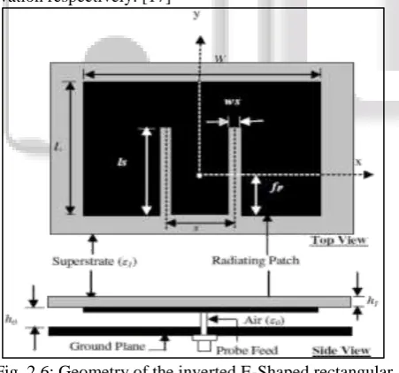
[image:4.595.311.548.67.187.2]G. Norbahiah Misran, et al. (2008), “Design and Development of Broadband Inverted E-shaped Patch Microstrip Array Antenna for 3G Wireless network” Summary- Microstrip patch antenna has been received tremendous attention since the last two decades and now it becomes a major component in the development of Smart Antenna System for Third-Generation Wireless Network proposed by the ITU-R under the banner of IMT-2000. Smart antenna consists of an array of antennas associated with it a base-band hardware and control unit (inclusive of the software algorithm) that have the capability to change its radiation pattern according to the direction of the user. This paper describes the design and development of broadband Inverted E-shaped patch microstrip array antennas for 3G wireless network. The antenna was designed for the IMT-2000 operating frequency range of 1.885–2.200GHz and was built as an array of 4x4 inverted E-shaped patches. The beam forming feed network comprises of commercial variable attenuators (KAT1D04SA002), variable phase shifters (KPH35OSC000), and the corporate 16-ways Wilkinson power divider which was developed in-house. The antenna successfully achieves the bandwidth of 16.14% (at VSWR: 1.5) with respect to the centre frequency of 2.045 GHz. The antenna is capable of scanning with the maximum scanning angle of ±30º and ±25º in azimuth and elevation respectively. [17]
Fig. 2.6: Geometry of the inverted E-Shaped rectangular patch antenna
H. Ka-Lam Lau, et al. (2006), “Design of a Circularly-Polarized Vertical Patch Antenna”
[image:4.595.57.283.395.606.2]Summary- A circularly-polarized vertical patch antenna is proposed and investigated. The design is achieved by simply adding two small stubs to the vertical patch. The antenna maintains the advantages of the original linearly polarized vertical patch antenna, such as simple structure, small size and wide bandwidth. It exhibits a gain of 8dBi over a 3 dB axial ratio bandwidth of 4%. [20]
Fig. 2.7: Geometry of CP-VPA with vertical stub.
I. Mauro Manzini, et al. (2004), “Polygonal Patch Antennas for Wireless Communications”
Summary- An effective design of polygonal patch antennas with multi frequency or broad-band operation modes for wireless communications is presented in this paper. It is shown how polygonal patches with suitable features may be obtained after a proper perturbation of conventional rectangular geometries, which inherently present poor bandwidth performances. These perturbed irregular geometries may support multiple resonances and, thus, may present a broad-band or multi frequency operation mode, even employing conventional patch antennas with a single dielectric substrate. These polygonal patches are efficiently analyzed through a numerical code based on the method of moments, with entire domain basis functions that accurately describe the radiation mechanism. After the presentation of the analysis and design techniques, some antenna layouts for modern wireless communication systems will be proposed. Such antennas are designed for both universal mobile telecommunication system and wireless local area network portable equipment with real-life finite ground planes. [21]
Fig. 2.8: Polygonal patch antenna with finite ground plane obtained by perturbation of a rectangular shape, designed for
a dual-band WLAN PC card. (a) Top and side views.
J. S. Maci, et al. (1997), “Dual-Frequency Patch Antennas”
[image:4.595.317.535.447.625.2]antennas. In this paper, a critical overview of possible solutions for dual-frequency patch antennas is presented, and future perspectives are outlined. [26]
Fig. 2.9: The geometry of the slotted cross-patch antenna
Fig. 2.10: The geometry of the cross-subarray patch antenna.
K. R.Waterhouse, (1995) “Small microstrip patch antenna”
[image:5.595.323.514.66.237.2]Summary- A novel small microstrip patch antenna is presented. The probe fed circular microstrip patch incorporates a single shorting post which significantly reduces the overall size of the Antenna Experimental and theoretical impedance behaviour and radiation characteristics of the modified patch are given. Very good agreement between experiment and theory was achieved. [27]
Fig. 2.11: schematic diagram of probe feed circular microstrip patch antenna with single shorting post.
L. DAVID M. POZAR, (1992) “Microstrip Antennas”
Summary- Microstrip antennas have been one of the most innovative topics in antenna theory and design in recent years, and are increasingly finding application in a wide range of modern microwave systems. In this paper emphasis is on new antenna configurations for improved electrical performance and manufacturability, and advances in the analytical modeling of microstrip antennas and arrays. [28]
M. ROBERT J. MAILLOUX, et al. (1981), “Microstrip Array Technology”
Summary- Past and present technological developments in microstrip antenna arrays are summarized. Emphasis is on exploring the potential of such arrays for satisfying the requirements of advanced military and commercial applications. [29]
IV. SOFTWARE USED
A. CST
Since the performance of electronic devices depends on electromagnetic behavior (EM), you need a quick and accurate account of how your design will behave in real world implementations - long before any prototype is built. The results of the ANSYS HFSS ™ simulation give you the confidence you need: the technology offers the most accurate response possible with the least involvement of the user. As a reference simulation tool for 3-D electromagnetic wave simulation, HFSS is essential for the design of high-frequency and / or high-speed components used in modern electronic devices.
Understanding the EM environment is essential to accurately predict how a component - or subsystem, system or end product - works in the field, or how it influences the performance of other components in the vicinity. HFSS addresses the full spectrum of EM problems, including losses due to reflection, attenuation, radiation and coupling.
spending a lot of time determining and creating the best mesh.
To solve the most demanding high-frequency simulations, all HFSS solvers are equipped with high performance computing (HPC) options including domain decomposition and distributed processing. HPC reduces computing time and leverages existing computing resources to solve very large simulations faster.
V. FEKO, IE3D
FEKO is a Method of Moments (MoM) tool that can be used to calculate the radiation pattern, impedance and gain of an antenna while mounted on some defined geometry. In addition, it can calculate the isolation or mutual coupling (S12) between pairs of antennas, the near fields around an antenna and the electric currents that flow on an antenna or the surrounding structure.
The basic flow of performing a FEKO analysis consists of
1) Building a geometry for the antenna (example – a wire to represent the antenna) in CADFEKO or EDITFEKO 2) Building a geometry to represent surrounding geometry
(for instance, can model an antenna on top of an airplane or an antenna on a supporting structure which will affect the antenna’s performance) in CADFEKO, EDITFEKO or an external tool
3) Meshing the Created Antenna and Surrounding Geometries (CADFEKO or EDITFEKO)
4) Requesting Solution Types and Setting Solution Parameters (CADFEKO or EDITFEKO)
5) Running the FEKO solver (FEKO)
6) Read in and interpret results using Post FEKO.
ZELAND’s IE3D is one of the most popular computer aided design or engineering software used by manufacturers/designers in the antenna design industry and this is due to the all-round functions a complete IE3D package provides.
The software comes with the features needed for circuit 3D Geometry modeling, high capacity electromagnetic design and signal integrity modeling. The features, Tools and functions that make it unique includes :
Full automation for repetitive tasks which can lead to major/ minor errors. Tasks such as; 3D geometry modeling, meshing and simulation falls under this group.
It incorporates MoM modeling techniques and also supports designs coming from other 3D EM design software.
Most importantly, the intuitive nature of its workspaces eliminates the need for a user to have extensive knowledge of EM modeling to design a mesh thereby simplifying the entire design process.
Year Title
Antenna ( Shape/ Modification ) Feed Technique Range
(GHz ) S - 11 (db) VSWR/Gain
Number of Bands
2016
Optimization of Z-Shape of Microstrip Antenna With
I-Slot using Discrete Particles Swarm Optimization (DPSO)
Algorithm.
Z-Shape With
I-Slot Inset Fed 3 to 5
3.5GHz = -19.40 4.3GHz =
-19.51
1.23 2
2015
EA Based Optimized T-Slot Patch Antenna for Bandwidth Improvement
T-Slot Microstrip
Line feed 5 to 13 5.5GHz=-20db NM multi
2015
Optimized Design of H-Slot Antenna for Bandwidth Improvement
H-Slot Microstrip Line feed 2.50 to 12.5 4.8 GHz=-14.5 9.35GHz=-22.2 9.7GHz=-22.8 1.07,1.01,
1.01 2
2014
Feed Analysis of Microstrip Antenna for UWB
Communication
Rectangular
Patch Antenna Probe Feed 1 to 10 4.9GHz=-17.51 NM multi
2013
Diamond Shaped Microstrip Patch Antenna
for Dual Band Operation
Diamond Shape rectangular patch with T-
Slot
Microstrip
Line feed 0 to 12
7.059GHz=-14.1 10.94GHz=-14
2 to 3 2
2008
Design & Development of Broadband Inverted E-Shaped Patch Microstrip
Array For 3G Wireless Network
Inverted E-Shaped Patch
Planar Array
Probe Feed 1.65 to
2.35 1.92Ghz=-53 1.07 1
2006
Design of Circularly Polarized Vertical Patch
Antenna
CP-VPA Probe Feed 3 to 6 4.2Ghz=-14 3db 1
1995 Small Microstrip Patch Antenna
Circular Patch With Single Shorting Post
Probe Feed 1.49 to
[image:6.595.39.558.331.752.2]1.57 1.54GHz=-23 NM 1
VI. CONCLUSIONS
In this survey paper compared different shape and different slot of antenna or different frequency ranges in between 1 to 10 GHz. In this frequency range is the most important frequency range for wireless application like Fi, Wi-MAX, 4G, 5G devices, LTE (Long Term Evolution), etc. The basis of parameter are - type of antenna shape, type of feed, frequency range, return loss, Voltage Standing Wave Ratio (VSWR), gain, number of band.
REFERENCES
[1] Swarnaprava Sahoo, Laxmi Prasad Mishra, Mihir Narayan Mohanty, ”Optimization of Z-Shape Microstrip Antenna with I- slot Using Discrete Particle Swarm Optimization (DPSO) Algorithm”,2nd international conference on intelligent computing ,communication and convergence (ICCC),Elsevier, 2016.
[2] Balanis A Constantine, “Antenna Theory: Analysis and Design”, 4th edition, 2016.
[3] Anindita Das, Mihir Narayan Mohanty, Laxmi Prasad Mishra, “EA Based Optimized T-Slot Patch Antenna for Bandwidth Improvement”, IJET (Engg. Journals), Vol 7 No 4, pp. 1357-1360, Aug-Sep 2015.
[4] Anindita Das, Mihir Narayan Mohanty, “Design of Optimized U-Slot Microstrip Antenna for Multiband Communication”, IJAER, ISSN 0973-4562 Vol. 10 No.44, pp. 31167-31174, 2015.
[5] Das, M.N. Mohanty and R. K. Mishra, “Optimized Design of H- Slot Antenna for Bandwidth Improvement”, IEEE Power, Communication and Information Technology Conference (PCITC), India, 2015.
[6] Shaktijeet Mahapatra, Mihir Narayan Mohanty, “Simulation and Feed Analysis of Microstrip Antenna for UWB Communication”, IEEE Conf. ICCPCT 2014, 18-20 Dec,Noorul Islam University, Kanyakumari, TN, India, 2014..
[7] Tung-Hung Hsieh, Yi-Ming Cheng, and Pi-Wei Chen, “Dual-Band Microstrip Antenna With Z-Shape Patch”, IEEE 2nd International Symposium on Next-Generation Electronics (ISNE), 2013.
[8] Kumari, R.; Kumar, M, “Diamond shaped Microstrip patch antenna for Dual Band Operation” IEEE Conference IMPACT, 2013.
[9] Prashant Ranjan, Nand Kishore, Indrasen Singh and V.S. Tripathi, “Inverted Z and circular slot Patch Antenna for WLAN and Wi-MAX”, IEEE 2nd International Conference on Power, Control and Embedded Systems, 2012.
[10] P. Ashoka Varthanana, N. Muruganb, G. Mohan Kumari, “An AHP based heuristic DPSO algorithm for generating multi criteria production–distribution plan”, Int J Adv Manuf Technol , springer ,pp 373-396 , 2012. [11] T. Bose, N. Gupta, “Design of an aperture-coupled
microstrip antenna using a hybrid neural network”, IET Microw. Antennas Propag., 2012, Vol. 6, Iss. 4, pp. 470–474, 2012.
[12] Amit A. Deshmukh, K. P. Ray, “Broadband Proximity fed half E-shaped Microstrip Antennas”, IEEE , 2011. [13] M.M. Sharma, Sanjeev Yadav, Ashok Kumar, Y.
Ranga, Deepak Bhatnagar, “Compact Elliptical Microstrip Patch Antenna with Slotted Ground for Ku-Band Applications” , IEEE , 2011.
[14] Hossein Eskandari, Mahmood Rafaei Booket, Manouchehr Kamyab, and Mehdi Veysi, “Investigations on a Class of Wideband Printed Slot Antenna”, IEEE antennas and wireless propagation letters, vol. 9, 2010.
[15] K. Shambavi and Zachariah C. Alex, “Printed Dipole Antenna With Band Rejection Characteristics for UWB Applications”, IEEE antennas and wireless propagation letter, vol. 9, 2010.
[16] Hala Elsadek, and Dalia M. Nashaat, “Multiband and UWB V-Shaped Antenna Configuration for Wireless Communications Applications”, IEEE antenna and wireless propagation letters, vol. 7, 2008.
[17] N. Mishran, et al., “Design and Development of Broadband Inverted E-shaped Patch Microstrip Array”, American Journal of Applied Sciences, Vol.5, No.4, pp. 427- 434, 2008.
[18] Ayopl, M.K.A Rahiml, T. Masril, M.N.A. Karim, M.Z.A. Abdul Aziz, “Modified Slotted Patch Electromagnetic Band Gap for Antenna Array Application”, IEEE Proceedings of Asia-Pacific Microwave Conference, 2007.
[19] T.A. Milligan, Modern Antenna Design, 2nd ed., IEEE Press, John Wiley & Sons inc., 2007.
[20] K. L. Lau, K. M., Luk and K. F., Lee, “Design of a circularly polarized vertical patch antenna”, IEEE Transactions on Antennas and Propagation, Vol. 54, No.4, pp. 1332-1335, 2006.
[21] Pawel Kabacik, Krzysztof Wincza, Monika Kamaszuk, “Optimizing Circular Polarization in Broadband Lightweight Patch Antennas”, IEEE, 2005.
[22] Balanis Constantine A, “Antenna Theory, Analysis and Design”, John Wiley & Sons, 2nd Edition, 2005. [23] T.A. Milligan, Modern Antenna Design, 2nd edition,
IEEE press, John Wiley & Sons inc., 2005.
[24] M. Manzani, A. Alù, F. Bilotti, and L. Vegni, “Polygonal Patch Antenna for Wireless Communication”, IEEE transanctions on vehicular technology. Vol. 53, No. 5, September 2004.
[25] R Garg, P. Bhartia, I. Bahl and A. Ittipiboon,“ Microstrip antenna Design Handbook”, Chapters 3 & 4, Artech House, Boston, London, 2001.
[26] S. Maci and G. Biffi Gentilli, “Dual – frequency patch antennas”, IEEE Trans Antennas Propagation Mag 39, pp.13-20, 1997.
[27] R. Waterhouse, “Small Microstrip patch antenna,” Electron. Letters, Vol. 31, No. 8, pp. 604-605, 1995. [28] D.M. Pozar, “Microstrip antennas”, IEEE Transaction
on Antenna and Propagation, Vol. 80, No.1, pp.79-91, 1992.
[29] R.J.Mailoux, J.F. Mellyenna, N.P.Kemweis, “Microstrip array Technology”, IEEE Trans. Antenna Propagation Magazine, Vol.29, No.1, pp. 25-27, 1981. [30] HFSS 13 – Ansoft 3D full-wave electromagnetic field