23
Reconfigurable Design of Rectangular to
Polar Converter using Linear Convergence
Anurag Vijay Agrawal
M.E. Scholar
Department of Electronics and Comm. Engg. NITTTR, Sector-26, Chandigarh (India)
Rajesh Mehra
Associate Professor
Department of Electronics and Comm. Engg NITTTR, Sector-26, Chandigarh (India)
ABSTRACT
In recent years, the growth of multimedia services and applications in digital data transmission has led to ever increasing demands of effective data transmission over the wired as well as wireless communication systems. Since digital communication systems need to deal with multimode and multiband operations on complex signals many-a-times, there is always a requirement of an efficient method for rapid phase and magnitude extraction. The proposed Rectangular to Polar Converter (RPC) has been implemented using fully parallel CORDIC, a Linear Convergence Algorithm, in vectoring mode. The design is synthesized with ISE 10.1 software, and implemented on 2v3000fg676-4. Synthesis results show that the design is able to work at 177.620 MHz with less hardware requirements.
General Terms
A rectangular to polar conversion is required so that transmitters must accommodate constant envelop signals as well as non-constant envelop signals to achieve multimode and multiband operations. In burst-mode communication systems, a rapid carrier is crucial. Hence a fast rectangular-to-polar conversion is needed. Delay-matching of phase as well as amplitude is crucial so that the restoration of the transmitted data at the receiver may be not be imperfect if the delays are unmatched.
Keywords
RPC, CORDIC, coordinate conversion, vectoring mode, atan2, FPGA.
1.
INTRODUCTION
In many digital communication applications, the efficient Rectangular to Polar conversion (RPC) is necessary [1],[2]. A polar modulation offers an alternative for multimode and multiband operations [3]. The conventional solutions for the implementation of polar transmitter adopted either analog approaches [4] using limiter and envelop detector or digital approaches using DSP engine [5]. These includes M-ary phase shift keying (PSK) receivers, down conversion in CDMA and UMTS, AM and FM demodulation for Digital Radios , automatic gain control and carrier tracking in digital implementation of Costas loop, modem synchronizers, and so on. Polar modulators that offer the capability of achieving high linearity and high efficiency simultaneously in wireless transmitter, in its digital implementation also require RPC. Polar transmission utilizes envelope and phase component to represent the digital symbols instead of the conventional I/Q format [6].
In addition, RPC is required in imaging systems and other DSP algorithms. In many applications, the phase calculation is more time-consuming and requires more accuracy than the magnitude calculation.
The implementation of this converter can be computationally burdensome given the need to implement the square-root function, the division operation, and arctangent operation. Various algorithmic methods can be used to implement an RPC. These are classified by the manner in which their computations are performed. These classes are the polynomial approximation algorithms, rational approximation algorithms, linear convergence algorithms and quadratic convergence algorithms. The first method uses a degree – n polynomial to approximate a function over the interval of interest, where n depends upon the amount of error that can be allowed in the calculation. Polynomials of higher degrees generate less error, but they obtain this precision at the expense of long computation time. A rational approximation is the ratio of two polynomials of degree n and degree m respectively. This ratio is then used to approximate the function over the interval of interest. With the addition of the second polynomial, higher accuracy can be achieved with lower degree polynomials. This reduces the number of multiplications and additions required to obtain the answer, but it introduces a division operation, which is one of the most time consuming instructions in any computational hardware.
The third class is of the linear convergence algorithms, which is a family of iteration equations, where the next value for each variable in the equation is based upon the current value of the variables. The time to compute the correct answer is a linear function of the number of bits of precision required by the digital system. The linear algorithms provide many opportunities to enhance operation through the modification of the basic algorithm. The difference between a linear convergence algorithm and a quadratic convergence algorithm is the speed with which they converge upon the correct answer. The time to compute the correct answer for the quadratic one is a logarithmic function of the number of bits of precision required. Unfortunately, quadratic convergence equations are made up of complex operations that require significant amount of computation time to calculate. As a result, the quadratic convergence algorithms have not been fully developed due to the complexity of the operations required to implement them.
This paper is organized as follows: in Section 2, the basic linear convergence algorithm CORDIC is revised; Section 3 presents the architectural description; Section 4 gives the proposed model design; Section 5 deals with the hardware implementation, verification and comparison results; and finally the conclusions are delivered in Section 6.
2.
CORDIC ALGORITHM
ancient principles of two-dimensional geometry. This algorithm was first published as a technique for efficiently implementing the trigonometric functions required for real-time aircraft navigation [7]. The simplest and most popular approach to perform Cartesian-to-polar coordinate conversion uses the CORDIC algorithm in the so-called vectoring mode [8]. CORDIC is unparalleled in its ability to encapsulate a diversity of math functions in one b a s i c set of iterations. It can be viewed as a single hardware architecture, with very minimal control overhead, having the ability to compute sine, cosine, cosh, sinh, arctan, atan2, square root, and polar-to-rectangular and rectangular-to-polar conversions, to name only a few functions. There are a plethora of alternatives for realizing, say, division in an FPGA, and most of the CORDIC alternatives provide good hardware efficiency. However, the algorithm remains unrivaled when it comes to processing multi-element I/O vectors, as is the case when converting from Rectangular to polar coordinates or vice versa. CORDIC falls into t h e class of shift-and-add algorithms — it is a multiplierless method dominated by additions. FPGAs are very efficient at realizing arbitrary precision adders, and so the CORDIC algorithm is in many ways a natural fit f o r b e i n g i m p l e m e n t e d w i t h FPGA architectures such as the Xilinx Virtex family of devices.
2.1
Iterative Equations
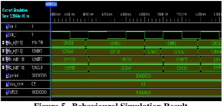
The CORDIC algorithm involves rotation of a vector v on the X-Y plane in circular, linear and hyperbolic coordinate system depending on the function to be evaluated [9]. This is a linear iterative convergence algorithm that performs a rotation iteratively using a series of specific incremental rotation angles selected so that each iteration is performed by shift and add operation. The norm of a vector in these coordinate systems is defined as , where p∈{1, 0, -1} represents a circular, linear or hyperbolic coordinate system respectively. Trajectory for the vector ui for
successiveCORDIC iterations is shown in Figure 1 for the circular coordinate system.
CORDIC method can be employed in two different modes, namely, the rotation mode and the vectoring mode. The rotation mode is used to perform the general rotation by a given angle θ. The vectoring mode computes unknown angle θ of vector by performing a finite number of microrotations.
The generalised equations of the CORDIC algorithm for an iteration can be written as [10] :
xi+1 = xi – p σi yi ρ-Sp,i
yi+1 = σi xi ρ-Sp,i + yi
zi+1 = zi – σi αp,i (1)
where σi represents either clockwise or anticlockwise direction
of rotation, ρ represents the radix of the number system, m denotes the type of coordinate system, Sp,i is the
nondecreasing integer shift sequence, and αp,i is the
elementary rotation angle. αp,i and Sp,i are related as
αp,i = tan-1( ρ-Sp,i) (2)
Figure 1 Rotation in Circular Coordinates
The shift sequence Sp,i depends on the coordinate system and the radix of number system. Sp,i affects the convergence of the algorithm and n affects the accuracy of the final result. The value of σi depends on the radix of the number system and is determined by the following equation assuming that vector is either in the first or in the fourth quadrant:
σi = (3)
where z and y are the steering variables in rotation and vectoring mode respectively. The required microrotations are not perfect and increase the length of the vector. In order to maintain a constant vector length, the obtained results have to be scaled by the scale factor
K = Пi ki ,
ki = (1 + p σi2 ρ-2Sp,i)1/2 (4)
The direction of iterative rotation is determined using zi
or yi depending on rotation mode or vectoring mode
respectively.
2.2
Vectoring Mode
In vectoring mode, the unknown angle of a vector is determined by performing a finite number of microrotations satisfying the relation
- θ = σ0 α0 + σ1 α1 + --- + σn-1 αn-1 (5)
The vectoring mode rotates the input vector through a predetermined set of n elementary angles so as to reduce the y coordinate of the final vector to zero as closely as possible. Therefore, the direction of rotation in every iteration must be determined based on the sign of residual y coordinate obtained in the previous iteration. The coordinates obtained in vectoring mode after n iterations are given by
2 2
n in in
x
K x
y
y
n
0
1
in
tan
x
in
n
y
z
[image:2.595.319.539.74.236.2]25
3.
ARCHITECTURE DESCRIPTION
[image:3.595.64.280.122.436.2]This paper presents unfolded (nonrecursive) architecture, as shown in Figure 2, for implementing the Rectangular-to-polar converter.
Figure 2 Fully Parallel CORDIC[11]
It uses a constant scaling factor, simply provided as an aggregate gain at the output. The precision of the input and output operands are 12 bits with 8 number of binary point bits. The implementation size of a parallel CORDIC design is directly proportional to the internal precision times the number of iterations. Instantiation of blocks must be done N times for an N bit precise output and all iterations are done in parallel and hence need not wait for N clock cycles. Also as dealing with a chain of inputs, this structure will prove to be more efficient one since the throughput of parallel structure is much greater. The shifters used in this architecture are constant shifters, which can be implemented in the wiring, so the hardware can be reduced. The design of CORDIC-based 2D Gaussian function and an efficient VLSI architecture suitable for FPGA implementation is presented, which is capable of processing one pixel per clock cycle and provides results in real time [12]. The pipelined architecture [13] uses the basic structure similar to that of a parallel CORDIC but it uses pipeline registers in between each iteration phase. The first output of an N-staged pipelined CORDIC is obtained after N clock cycles. Thereafter, outputs will be generated during every clock cycle. Another drawback of pipelined structure is the increase in area introduced by the registers.
The iteration count i is initialized to 0 along with the angle register z. Each iteration contributes one additional bit of precision to the final result. The conditional test in the algorithm serves to minimize the value of y at each
time-step. When the required number of iterations have been completed the angle register z contains an approximation to atan2(x,y). The CORDIC algorithm does not converge for input angles |θ | > 900, in order to support the full range of input angles the computation is decomposed into three stages [14]. First, a course angle rotation is performed to map the input argument into quadrant 1, next N micro rotations (using the CORDIC algorithm) are performed, and finally a quadrant correction is applied to account for the coarse angle rotation. The quadrant mapping is straightforward and consists of a comparator, negator and a multiplexer.
The reason of using two – argument arctangent function is to enhance the angle convergence range because one-argument arctangent function does not distinguish between diametrically opposite directions. For example, the anticlockwise angle from the x-axis to the vector (1, 1), calculated in the usual way as arctan(1/1), is π/4 (radians), or 45°. However, the angle between the x-axis and the vector (−1, −1) appears, by the same method, to be arctan(−1/−1), again π/4, even though the answer clearly should be −3π/4, or −135°. The atan2 function takes into account the signs of both vector components, and places the angle in the correct quadrant. Thus, atan2(1, 1) = π/4 and atan2(−1, −1) = −3π/4. Additionally, the ordinary arctangent method breaks down when required to produce an angle of ±π/2 (or ±90°). For example, an attempt to find the angle between the x-axis and the vector (0, 1) requires evaluation of arctan(1/0), which fails on division by zero. In contrast, atan2(1, 0) gives the correct answer of π/2.
The type of scaling tends to increase the overall latency [16]. Therefore, to minimize the latency, the normal iterations and the scaling should be separated. In our design, the scaling factor is taken as a constant K = 1.646760 because the number of the iterations is constant. The scaling factor is simply provided on the output of the CORDIC magnitude (port X) and is not included in the CORDIC computation.
4.
PROPOSED MODEL DESIGN
26
Figure 3 Proposed Model
The waveforms for the rectangular inputs and the magnitude and atan2 waveforms, as generated at the output of the Simulink model on a scope are shown in Figure 4.
Figure 4 Input and Output waveforms on Scope
5.
HARDWARE IMPLEMENTATION
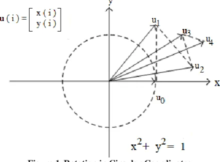
[image:4.595.61.291.83.280.2]The proposed architecture has been implemented in an XC2V3000FG676-4 Xilinx FPGA device. Verification process includes functional simulation, and behavioural simulation processes. These consist of the test bench generation and then simulated waveforms for the magnitude and the phase are generated as shown in Figure 5. This simulation was done to know if VHDL design was matched with the model.
Figure 5 Behavioural Simulation Result
Area and maximum working frequency were obtained with the 10.1 Xilinx ISE tool. Figure 6 shows the area utilization of proposed design implemented on 2v3000fg676-4 target device in terms of slices, flip-flops and LUTs.
Logic Utilization Used Available Utilization
Slices 217 14336 1%
Flip Flops 370 28672 1%
4-input LUTs 326 28672 1%
Bonded IOBs 50 484 10%
[image:4.595.56.284.334.474.2]GCLKs 1 16 6%
Figure 6 Area Utilization
The minimum period is 5.630 ns (Maximum Frequency 177.620 MHz). According to the Xilinx XPower Analyzer report, the total estimated power consumption is 81mW, out of which 41mW has been consumed by the core unit, 33mW by the auxiliary pins and the unit, and only 7mW by the IO buffers, when the estimated junction temperature is 26 degree C at an ambient temperature of 25 degree C.
The proposed RPC is compared with other implementations [15] on the same target device. Whereas [15] is providing only phase, ours is computing the phase as well as the magnitude. The comparison chart is shown in Table 1.
The proposed architecture provides more than 50% savings in the FPGA slices when compared with pipelined CORDIC approach, whereas about 44% in comparison to LUT based method with no use of pipeline registers. This saving will be more as the number of pipeline registers is increased. Also the proposed model provides a 7-10 fold increase in the speed, but as in [15], if registers are increased in the pipeline, it provides speed enhancement at the cost of more hardware. Also the proposed model is saving 50-65% power, when compared with the existing models with less number of pipelined registers.
Table 1 Existing[8] vs Proposed Model Comparison
Parameters Pipelined based model [15]
LUT based model [15]
Proposed model
No. of Slices 384 436 217
Max. Freq. (MHz) 25.4 16.7 177.62
Power Consumption (mW)
127 163.1 81
The minimum input arrival time before clock is 3.536ns and the maximum output required time after clock is 5.446ns.
6.
CONCLUSION
[image:4.595.311.547.470.555.2] [image:4.595.54.281.595.703.2]27 power than the existing ones. As a result, the proposed
architecture is most suitable for high speed digital communication applications and provides an alternative for multimode and multiband operations that can support various modulation formats such as EDGE, GSM, CDMA, TDMA, and WCDMA and can overcome from the problems associated with I/Q based transmitter design too.
7.
ACKNOWLEDGMENTS
The authors would like to express their sincere regards and deep sense of gratitude to Prof. (Dr.) Samir Kumar Das, Director, NITTTR, Chandigarh a n d Dr. SBL Sachan, Professor and Head, Electronics & Communication Engineering Department for their constant inspirations and support throughout this research work.
8.
REFERENCES
[1] David D. Hwang, Dengwei Fu, Alan N.W., ― A 400-MHz Processor for the Conversion of Rectangular to Polar Coordinates in 0.25-µm CMOS‖, IEEE Journal of Solid State Circuits,vol. 38, no. 10, pp. 1771-1775, 2003.
[2] Sala, F. Salidu, F. Stefani, C. Kutschenreiter, A. Baschirotto, ―Design considerations and implementation of a DSP-based car-radio IF processor‖, IEEE Journal of Solid State Circuits,vol. 39, no. 7, pp. 1110-1118, 2004.
[3] L. R. Kahn, ―Single-sideband transmission by envelope limination and restoration,‖ Proc. IRE, vol. 40, no. 7, pp. 803–806, 1952.
[4] D. Rudolph, ―Out-of-band emissions of digital transmissions using Kahn EER technique,‖ IEEE Trans. Microw. Theory Tech., vol. 50, no. 8, pp. 1979–1983, 2002.
[5] C. Chen, H. Ko, Y. Wang, H. Tsao, K. Jheng, and A.Wu, ―Polar transmitter for wireless communication system,‖in Proc. ISPACS, pp. 613-616, 2005.
[6] P. Nagle, P. Burton, E. Heaney, and F. McGrath, ―A wide-band linear amplitude modulator for polar transmitters based on the concept of interleaving delta modulation,‖ IEEE Journal of Solid-State Circuits, vol. 37, pp. 1748-1756, 2002.
[7] J. Volder, ―The CORDIC trigonometric computer technique,‖ IRE Trans. Electron. Comput., vol. EC-8, pp. 330–334, 1959.
[8] R. Andraka, ―A survey of CORDIC algorithms for FPGA based computers,‖ in Proc. ACM/SIGDA 6th Int. Symp. FPGAs, Monterey, CA, pp. 191–200, 1998.
[9] F. Angarita, A. Perez-Pascual, T. Sansaloni, J. Valls, ―Efficient FPGA Implementation of CORDIC Algorithm for Circular and Linear coordinates‖, IEEE, pp. 535-538, 2005.
[10]J. S. Walther, ―The story of Unified CORDIC,‖ Journal of VLSI Signal Processing, vol. 25, no. 2, pp. 107–112, 2000.
[11]E. Antelo, J. Villalba, ―Low Latency Pipelined Circular CORDIC‖, ARITH-17 2005:17th
IEEE Symposium on Computer Arithmetic, pp. 280-287, 2005.
[12]J. Sudha, M. C Hanumantharaju, V. Venkateswarula, Jayalaxmi H, ―A Novel Method for Computing Exponential Function using CORDIC Algorithm‖, Elsevier, SciVerse ScienceDirect, Procedia Engineering 30 (2012) , pp. 519-528, 2012.
[13]Sung-Won Lee, Ki-Seok Kwon, In-Cheol Park, ―Pipelined Cartesian-to-Polar Coordinate Conversion Based on SRT Division‖, IEEE transactions on Circuits and Systems-II: Express Briefs, Vol.54, No.8, pp. 680-684, 2007.
[14]H.Y. Ko, Y. C. Wang, A. Y. Wu, ―Digital Signal Processing Engine Design for Polar Transmitter in Wireless Communication Systems‖, Proc. of IEEE ISCAS Conference, pp. 6026-6029, 2005.
[15]R.Gutierrez, J.Valls,‖Low-Power FPGA-Implementation of Atan(Y/X) using Look-Up Table Methods for Communication Applications‖, Springer Journal of Signal Processing Systems (2009), Vol. 56, pp. 25-33, 2009.
![Figure 2 Fully Parallel CORDIC[11]](https://thumb-us.123doks.com/thumbv2/123dok_us/8107541.789914/3.595.64.280.122.436/figure-fully-parallel-cordic.webp)