A Priority based SRM Algorithm for VOQ Packet
Switch Architecture
Harendra Singh
Deptt. of Computer Science, UCER. Allahabad, INDIA.
Prabhat Ranjan,
PhD.Computer Science & Engg. Deptt, MNNIT Allahabad. Allahabad, INDIA
ABSTRACT
Virtual Output Queuing (VOQ) is used to overcome the head-of-line (HoL) blocking problem in input-queued (IQ) packet switches. There are a lot of research has been devoted to design iterative arbitration algorithms to find maximum throughput of this architecture. In this paper approximating maximum size matching (MSM) algorithm called Selective Request Matching (SRM) has been proposed, which performs extremely well under various traffic models and easy to implement in hardware.
Keywords
Selective request matching, highest priority, pointer transmission, request, grant.
1.
INTRODUCTION
The introduction of virtual output queues (VOQs), where one queue per output port is placed in an input port of an input queue (IQ) packet switch, is used to remove the Head-of-Line (HoL) blocking problem [1]. Head-of-Line (HoL) blocking problem is a performance limiting phenomenon that occurs in buffered switches. HoL blocking causes idle outputs to remain impending to the delivery of high throughput.
When using a first-in-first-out (FIFO) queuing discipline at the input queues, due to HoL blocking problem, they only provide a maximum throughput of 58.6% under uniform traffic [14]. VOQ is used to overcome the drawbacks of an input queuing switch and combine the features of both input queuing switch and output queuing switch. In a VOQ switch, rather than maintaining a single FIFO queue for all packets, each input maintains N queues, one for each output. By using VOQ, no additional speedup is required and HoL blocking can be eliminated.
Considerable work has been done on scheduling algorithms for VOQ switches. These algorithms can be categories in two ways: maximum size matching (MSM) and maximum weight matching (MWM). It has been proved that maximum weight matching algorithm can achieve 100% throughput for i.i.d. arrivals (uniform or non-uniform) [3] [4]. Unfortunately, these scheduling algorithms have typically been slow, inefficient to implement [5] [6]. MWM algorithms have a high running time (O(N3logN)).
A number of practical maximum size matching algorithms have been proposed to achieve high throughput [7] [8]. However, they may need a large number of iterations to achieve satisfactory matching results. Schemes based on round-robin matching, such as PIM [5], iSLIP [9], FIRM [10], DRRM [11], and SRRRS [12] have been shown to deliver 100% throughput under uniform traffic. With a single-stage switch, the exhaustive dual round robin matching (EDRRM) [13] has been shown to achieve a throughput higher than iSLIP and DRRM under non-uniform traffic pattern.
This paper proposed a new MSM algorithm called selective request matching (SRM), which performs much better than the
other maximum size matching algorithm. It is faster and easy to implement.
2.
RELATED WORK
A number of practical maximum size matching algorithms have been proposed to achieve high throughput and they are easy to implement in hardware. They may need a large number of iterations to achieve satisfactory matching results. In each iteration, the inputs send requests to the outputs for which they have packets, then each output selects one request in round robin fashion, and issues a grant to it, at last each input accept to one grant. In each iteration, only the unmatched inputs and outputs will be considered.
Parallel iterative matching (PIM), basic round robin matching (RRM) [2] and iterative least recently used (iLRU) [15] having no more than 65% throughput under uniform traffic. But iSLIP and other algorithms can achieve 100% throughput under uniform i.i.d. Bernoulli arrivals, iSLIP is currently being used by CISCO products, because of its simplicity and can operate at high speed.
The iSLIP scheduling algorithm uses rotation priority arbitration to schedule each active input and output in turn. The iSLIP scheduling algorithm can be briefly described as follows: Step1. Request: Each unmatched input sends a request to every output for which it has a queued packets.
Step2. Grant: If an output receives any requests, it chooses the one that appears next in a fixed. Round robin scheduling starts from the highest priority element. The output notifies each input whether or not its request was granted. The pointer to the highest priority element of the round robin schedule is incremented to one location beyond the granted input if and only if the grant is accepted in Step3.
Step3. Accept: If an input receives a grant, it accepts the one that appears next in a fixed. The pointer to the highest priority element of the round robin schedule is incremented to one location beyond the accepted output.
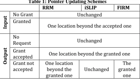
[image:1.595.307.550.630.767.2]FIRM algorithm is almost the same as iSLIP. The main difference between RRM, iSLIP, and FIRM is in updating their pointers. Table I shows their updating scheme. The updating scheme plays an important role in improving the performance.
Table 1: Pointer Updating Schemes
RRM iSLIP FIRM
In
p
u
t No Grant Unchanged
Granted
One location beyond the accepted one
Out
p
u
t
No
Request Unchanged Grant
accepted One location beyond the granted one Grant not
accepted One location beyond the
granted one Unchanged
The granted
PIM, iSLIP and FIRM algorithms are using the same steps to find maximal matching (Request, Grant, and Accept), but basic difference between them is choosing the request for grant. Table 2 shows the main difference between PIM, iSLIP, and FIRM.
Table 2: Grant Selection
Input Choice Output Choice
Random Round Robin FCFS
Random PIM
Round Robin iSLIP
FCFS FIRM
PIM chooses requests randomly to grant, where iSLIP chooses the one that appears next in a fixed, round-robin schedule starting from the highest priority element, and FIRM chooses the request for granting in FCFS approach.
Another important algorithm is DRRM (Dual Round Robin Matching). This scheme is little bit different from the conventional approaches (like PIM, iSLIP, or FIRM) where we uses Request-Grant-Accept steps. The DRRM algorithm uses only two steps by eliminating Accept step, because each input only makes one request instead of sending out all the requests. Step1. Request:
Each input sends an output request corresponding to the first nonempty VOQ in a fixed round robin order, starting from the current position of the pointer. The pointer of the input arbiter is incremented by one location beyond the selected output if and only if the request is granted in step 2.
Step2. Grant:
If an output receives one or more requests, it chooses the one that appears next in a fixed round-robin schedule starting from the current position of the pointer. The pointer of the output arbiter is incremented to one location beyond the granted input. If there are no requests, the pointer remains where it is.
Figure 1 shows an example of the DRRM scheme. In a request phase, each input makes a request to the output at or after the request arbiter in the round-robin schedule, for which it has a cell. Input 1 has cells destined for both output 1 and 2. Since r1=1, input one makes a request for output 1 and r1 incremented
by one for next time. In same fashion, r2=2 but input 2 have no
[image:2.595.55.294.567.726.2]cells for output 2 so it sends request to output 3 and so on.
Figure 1: Dual Round Robin Matching (DRRM) Scheme
In the grant phase, each output selects at most one input. Since g3=3, output 3 grants input 3 and g3 is updated to input 4 and so
on.
The Dual Round-Robin Matching (DRRM) switch [16] [17] builds and improves on the ideas incorporated in iSLIP. It has been proven that DRRM can achieve 100% throughput under i.i.d. uniform traffic [17]. Furthermore, the DRRM scheme provides fairness and prevents starvation. It has lower implementation complexity compared to algorithms with similar performance and is scalable. According to simulation results [17], under uniform bursty traffic, the average delay of a DRRM switch varies approximately linearly with burst length, but under non-uniform traffic the throughput drops below 100%.
The difference between DRRM and EDRRM is EDRRM uses exhaustive service in an achieved match by keeping the match between a queue and an output port until the occupancy of the matched queue is exhausted. The pointers of inputs and outputs are updated in a different way from DRRM. EDRRM has shown higher throughput than iSLIP and DRRM under non-uniform traffic pattern at the cost of low performance under uniform traffic.
The implementation of EDRRM and DRRM are comparable with both having lower complexity than iSLIP. The only performance drawback of EDRRM is that it does not achieve 100% throughput under uniform traffic for a range of switch sizes [12].
The selective request round robin scheduling (SRRRS) uses selective request based on highest priority input and then work similar to iSLIP or FIRM. The algorithm is composed of 4 steps: Step1. Pointer Transmission:
Each output sends a signal to its highest priority input. The highest priority is set as similar to RRM or iSLIP.
Step2. Request:
For each input, it checks for each VOQ where a signal from the corresponding output is received in step 1.
1. If there is any packet waiting for such VOQ, request will be made for the corresponding output.
2. Otherwise, the input will send all the requests. Step3. Grant:
It works the same as iSLIP or FIRM. Step4. Accept:
It is also the same as iSLIP or FIRM.
SRRRS has lower average delay than iSLIP, FIRM, and DRRM under uniform traffic model, especially when 0.6<load<0.9 [13]. The SRRRS scheme has the two main disadvantages. First, it usage four steps in a iteration which may take time than the other algorithms. Second, its dependency on pointer updation likes iSLIP or FIRM. Even it gives better results than the other algorithms on any traffic model [13].
In this paper proposed a new algorithm which gives the better result than the others.
3.
THE PROPOSED SRM ALGORITHM
3.1
Algorithm
The proposed selective request matching (SRM) algorithm uses three steps to find the maximum matching in minimum iteration than the other algorithms. The steps are as follows:
Step1. Pointer Transmission:
Each output sends a signal to its highest priority input. The highest priority is set by the highest packets waiting in any VOQ. If two or more VOQs have the same number of packets than the highest priority is set as FCFS fashion. An input may receive several signals from different outputs as the pointers are not always desynchronized.
Step2. Request:
Each input receive one or more signals, It chooses one of them in a round robin fashion and a request will be made for the corresponding output. Rest of the input ports waits for next iteration.
Step3. Grant:
If an output port receives a request, it grants to that one. By the input line synchronization each output line receives only one request.
3.2
A Concept of algorithm
The SRM algorithm is composed with 3 steps: pointer transmission, request, and grant. This algorithm is explained by using two examples; one is generated from the simulation of FIRM for an 8x8 switch under uniform i.i.d. Bernoulli traffic, second is generated from the simulation of DRRM for a 4x4 switch under uniform i.i.d. Bernoulli traffic.
3.2.1 An example for an 8x8 switch
The SRM algorithm sends only selected request to the output lines instead of sending all available requests. This algorithm uses pointer transmission to select an individual request among others. An input may receive several signals from different outputs as the pointers are not always desynchronized. In this case the selection of request is done on round robin fashion. Output lines grant the requested input line if it gets any request. Table 3 shows the length of VOQs for 8x8 switch under i.i.d. Bernoulli traffic for FIRM algorithm.
[image:3.595.303.547.102.235.2]The accept step can be omitted from the algorithm just by sending only one request from the each input lines. In this scenario, each input line sends only one request to its corresponding output, and then output sends a grant to the input. It may be possible that an output line receives more than one request; in that case the output line uses round robin selection for an input line.
Table 3: Length of VOQs
Output
Input
1 2 3 4 5 6 7 8
1 4 0 1 3 5 5 4 1
2 3 1 6 4 0 2 2 5
3 1 1 6 4 0 11 2 3
4 1 6 12 2 1 5 1 6
5 1 0 2 7 8 1 3 0
6 17 4 5 0 6 1 0 0
7 5 2 5 1 3 2 1 1
8 8 1 4 9 3 2 2 2
By the table 3, only the input lines selected to send requests, which have the only one highest priority request. If an input line has two or highest number of packets, then the selection is done in round robin fashion.
The table 4 shows the selected output lines, which sends a signal to its highest priority input.
Table 4: Pointer Transmission
Output
Input
1 2 3 4 5 6 7 8
1 4 0 1 3 5 5 4 1
2 3 1 6 4 0 2 2 5
3 1 1 6 4 0 11 2 3
4 1 6 12 2 1 5 1 6
5 1 0 2 7 8 1 3 0
6 17 4 5 0 6 1 0 0
7 5 2 5 1 3 2 1 1
8 8 1 4 9 3 2 2 2
[image:3.595.303.547.290.424.2]The table 5 shows the selected requests that are requested to the corresponding output lines. If an input line receives multiple pointer transmissions then the request selection is done in round robin fashion.
Table 5: Selected request to send
Output
Input
1 2 3 4 5 6 7 8
1 4 0 1 3 5 5 4 1
2 3 1 6 4 0 2 2 5
3 1 1 6 4 0 11 2 3
4 1 6 12 2 1 5 1 6
5 1 0 2 7 8 1 3 0
6 17 4 5 0 6 1 0 0
7 5 2 5 1 3 2 1 1
8 8 1 4 9 3 2 2 2
These requests will be granted in third step by output lines, when they get the corresponding request.
[image:3.595.304.545.516.560.2]The next iteration finds the remaining selected matching to find maximum size matching of 8x8 switch. Table 6 shows the list of the final maximum matching of input and output lines, which comes after two iterations.
Table 6: Granted Requests
Output 1 2 3 4 5 6 7 8
Grant Request 6 4 2 8 5 3 1 7
Each output is granting a different input, so the maximum size matching is made.
3.2.2 An example for 4x4 switch
In an another example taken from the DRRM algorithm, which shows the length of VOQs for 4x4 switch under i.i.d. Bernoulli traffic for DRRM algorithm.
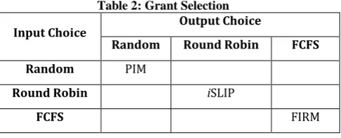
[image:3.595.48.292.587.722.2]For the first step output lines sends the pointers to its highest priority inputs. The highest priority is set to the highest waiting packets in a VOQ. Table 7 shows the length of VOQs in 4x4 switch.
Table 7: Length of VOQs
Output
Input 1 2 3 4
1 2 1 0 0
2 1 0 2 1
3 0 0 3 1
[image:3.595.343.504.686.763.2]In step 2, the input lines receive the pointers to send requests to the output lines. If an input line receives more than one pointer it chooses one in round robin fashion. In table 8 each input received a single pointer, so these are the requests to send to the outputs. Table 9 shows the selected requests to send to the outputs.
Table 8: Pointer Transmission
Output
Input 1 2 3 4
1 2 1 0 0
2 1 0 2 1
3 0 0 3 1
4 0 1 1 0
Table 9: Selected request to send
Output
Input 1 2 3 4
1 2 1 0 0
2 1 0 2 1
3 0 0 3 1
[image:4.595.91.253.140.296.2]4 0 1 1 0
[image:4.595.367.485.242.343.2]Table 10 shows the list of the final maximum matching of input and output lines that comes after a single iteration.
Table 10: Granted Requests
Output 1 2 3 4
Grant Request 1 4 3 2
This example shows that in less number of iterations maximum matching can be found with proposed SRM algorithm.
4.
PERFORMANCE EVALUATION
There are a number of factors that would lead to select one scheduling algorithm over another in switch designing.
First, it must be simple to implement. A complex algorithm is not only more expensive in area and power, but likely to provide less performance, particularly if each iteration requires off-chip communication.
Second, the algorithm must provide high throughput and avoid starvation for any flow pattern, this is because real-time network traffic is rarely uniformly distributed over inputs and outputs. A number of algorithms provide high throughput.
Third, the algorithm should provide high throughput for bursty traffic, always a network shows busty nature and algorithm should ready to process.
The evaluation of these algorithms under four different types of traffic models are as follows:
Uniform traffic, Bursty traffic, Cross-shaped traffic, and Hot-spot traffic.
For uniform traffic, the packets are Bernoulli arrivals, i.i.d., with destinations uniformly distributed equally over all outputs. Uniform traffic is identical to check algorithms for equally distributed load.
For bursty traffic, busy and idle period appear alternatively; for bursty period there is a packet arriving in each time slot; and for idle period there is no packet arriving in any time slot. The average loads of the inputs are same, and the destinations are uniformly distributed over all outputs.
2x x x x
2x x x x
2x x x x
2x x x x
(for a 4x4 switch )
For hot-spot traffic, the arriving packets are unbalanced they comes for a single output line or they may come in for single input line. Traffic matrix of hot-spot traffic is like:
For cross-shaped traffic, if output 0 is the “hot-spot” and each flow is Bernoulli arrivals, then the traffic matrix of cross-shaped traffic is like:
0 x 0 0
x x x x
0 x 0 0
0 x 0 0
(for a 4x4 switch )
[image:4.595.92.253.328.372.2]In this performance evaluation, all the four traffic models are considered to check the performances of the all leading algorithms with newly proposed Selective Request Matching algorithm. The following figures show the results of one iteration.
Figure 2: Relative Average Delay under Uniform Traffic
0.1 0.2 0.3 0.4 0.5 0.6 0.7 0.8 0.9 1.0
0 10 20 30 40 50 60
32x32 Switch under bernoulli-iid-uniform traffic
R
el
at
ive
Ave
ra
ge
D
el
ay
Normalized Load ISLIP
FIRM DRRM SRRR SRM
[image:4.595.323.526.419.544.2]Figure 2 shows the result performance of the algorithms under uniform traffic model. The performance of iSLIP and DRRM is very close. FIRM has a better performance than iSLIP and DRRM under high load basically when greater than 0.7. SRRRS and SRM has a lower average delay than all of the three algorithms for any load, but SRM is quite good than the SRRRS.
Figure 3: Relative Average Delay under Bursty Traffic
0.1 0.2 0.3 0.4 0.5 0.6 0.7 0.8 0.9 1.0 0
5 10 15 20 25 30 35 40 45
32x32 Switch under uniform burty Traffic
R
el
at
ive
Ave
ra
ge
D
el
ay
Normalized Load ISLIP
FIRM DRRM SRRR SRM
[image:4.595.320.509.626.759.2]Figure 3 shows the result performance of the algorithms under non-uniform bursty traffic model. The performance of iSLIP and FIRM is very close and DRRM performance is degraded by others. SRRRS and SRM has again a lower average delay than all of the three algorithms for any load, especially when 0.6<load<0.95.
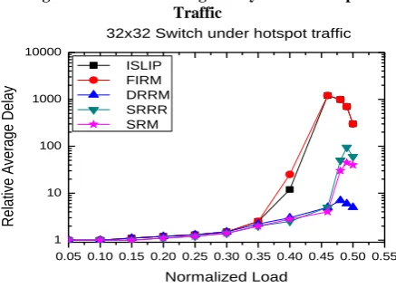
Figure 4: Relative Average Delay under Hot-spot Traffic
0.05 0.10 0.15 0.20 0.25 0.30 0.35 0.40 0.45 0.50 0.55 1
10 100 1000 10000
32x32 Switch under hotspot traffic
R
e
la
tive
Ave
ra
g
e
D
e
la
y
Normalized Load
ISLIP FIRM DRRM SRRR SRM
Figure 4 shows the result performance of the algorithms under hot-spot traffic model. FIRM and iSLIP shows similar performance, with FIRM a little wrose. SRRRS has a better result than these two algorithms, where SRM has too good result than these algorithms. However, DRRM shows especially good result under hot-spot traffic model. It is because the unbalance happens on the outputs, with inputs making decisions of what matches to make.
[image:5.595.64.278.472.645.2]Figure 5 shows the result performance of the algorithms under cross-shaped traffic model. SRM shows much better result than the other algorithms. The performance of DRRM is especially bad under higher load. Other algorithms are shown an average performance under higher load.
Figure 5: Relative Average Delay under Cross-shaped Traffic
0.01 0.02 0.03 0.04 0.05 0.06 0.07
1 10 100 1000
32x32 Switch under crossshaped traffic
R
e
la
tive
Ave
ra
g
e
D
e
la
y
Normalized load
ISLIP FIRM DRRM SRRR SRM
From the above results performance, it is shown that the new proposed algorithm Selective Request Matching is much better than the other algorithms and here performance evaluation of SRM considered no matter in what kind of traffic model is used. In fact, the traffic models we have considered cover most cases even some extreme cases. The proposed SRM algorithm is still better than the other algorithms.
5.
CONCLUSION
This paper introduced a new practical scheduling algorithm for VOQ switches. By the evaluation performance results we have shown that it achieves better performance than the other practical algorithms under variant traffic models, without adding much complexity. It requires lesser number of iteration to the maximal matching for VOQ switches and gives the great performance than the other practical algorithms. SRM meets the criterion of a good scheduling algorithm: good performance, fast and simple to implement.
This proposed algorithm adopted the highest priority concept for in VOQ switches. Schemes based on the proposed concept decrease the needed number of iterations performed in VOQ network switches to achieve high throughput, so can be used where selection approaches are required.
6.
REFERENCES
[1] M. Karol, M. Hluchyj, “Queuing in High-performance Packet-switching”, IEEE J. Select. Area Communication, Vol. 6, pp. 1587-1597, Dec 1988.
[2] N. McKeown, “Scheduling Cells in an Input-Queued Switch,” PhD thesis, University of California at Berkeley, May 1995.
[3] N. McKeown, V. Ananthram and J. Walrand, “Achieving 100% throughput in an input-queued switch”, IEEE INFOCOM ’96, pp. 296-302.
[4] N. McKeown, A. Mekkittikul, V. Ananthram and J. Walrand, “Achieving 100% throughput in an input-queued switch”, IEEE Trans. Communications, Vol. 47, No.8, pp. 1260-1267, Aug. 1999.
[5] Anderson T.; Owicki S.; Saxe J.; and Thacker C. “High speed switch scheduling for local area networks.” ACM Trans. on Computer Systems. Nov. 1993 pp. 319-352. [6] Karol M.; Eng K.; Obara H. “Improving the performance of
input-queued ATM packet switches” Proc. of IEEE INFOCOM ’92, pp. 110-115.
[7] P. Krishna, N. S. Patel, A. charny and R. Simcoe, “On the speedup required for work-conserving crossbar switches”, IWQOS’98, May 1998.
[8] A. Mekkittikul and N. McKeown, “A practical scheduling algorithm to achieve 100% throughput in input-queued switches”, IEEE INFOCOM 98, Vol. 2, pp. 792-799, April 1998.
[9] N. McKeown, “Scheduling algorithms for input-queued cell switches,” Ph.D. dissertation, Dept. Elect. Computer Science, Univ. California at Berkeley, Berkeley CA, 1995. [10] D. N. Serpanos, and P. I. Antoniadis, “FIRM: A Class of
Distributed Scheduling Algorithms for High-speed ATM Switches with Multiple Input Queues,” PROC. IEEE INFOCOM 2000, pp. 548-555. 2000.
[11] H. J. Chao, J. S. Park, “Centralized Contention Resolution Schemes for a large-capacity Optical ATM Switche,” IEEE ATM Workshop 1998, pp. 11-16, May 2001.
[12] Y. Li, S. Panwar, H.J. Chao, “The Dual Round-robin Matching Switch with Exhaustive Service,” IEEE HPSR 2002, pp. 58-63 2002.
[14] M.J. Karol, M.G. Hluchyj, S.P. Morgan, “Input Verses Output Queuing on a Space-Division Packet Switch”, IEEE Transactions on Communications, 35:1347-56, 1987. [15] N. Mckeown, and T. E. Anderson, “A Quantitative
Comparison of Iterative Scheduling Algorithms for Input-Queued Switches,” Computer Networks and ISDN systems, vol.30, pp. 2309-2326, 1997.
[16] Y. Li, S. Panwar, H. J. Chao, “On the performance of a Dual Round-Robin switch,” IEEE INFOCOM 2001, vol. 3, pp. 1688-1697, April 2001.