Nonradiating Edges Gap-Coupled Multiple Resonator
Dual and Tri-Band Microstrip Antennas
V.V.Mapare
Sinhgad Institute of Technology opp. Mumbai-Pune expressway
Lonavala. Dist.Pune.
S. V. Mapare
Sinhgad Institute of Technology opp. Mumbai-Pune
expressway Lonavala. Dist.Pune.
G.G.Sarate
, PhD.Government polytechnic Amravati.
ABSTRACT
A rectangular microstrip antenna for dual band and tri-band is developed using a parasitic technique. Single rectangular microstrip is splitted into multiple resonators along the width and gap coupled to non-radiating edges. The proposed structure gives sufficient separation between the operating frequencies increasing bandwidth for dual band and tri-band. It covers the frequency range from 1900 MHz to 3 GHz covering Universal Mobile Telecommunication System (UMTS, 1920-2170 MHz), Wireless Local Area Network (WLAN, 2400-2483.5 MHz) and low band Worldwide Interoperability for Microwave Access (WIMAX, 2.5 to 2.8 GHz). Simulation results are presented and discussed.
Key words: Dual band rectangular microstrip antenna, gap coupled rectangular microstrip antenna, multiple resonators, parasitic resonators, triple band rectangular microstrip antenna.
1. INTRODUCTION
Modern communication systems, such as those for satellite links (GPS, vehicular, etc.), as well as emerging applications, such as wireless local networks (WLAN), often require compact and low-cost antennas for dual and multifrequency bands [1]. The design of a microstrip patch antenna with different shapes to create multi-band has been achieved by using different shaped-slots [2]-[5],[10]. The characteristic feature of gap coupled microstrip antennas (MSAs) is that they generate multiple resonances. The separation between these resonances depends to a greater extent on the resonant frequencies of the individual resonators, and also to some extent on the gap and the feed point location [9]. Dual and tri-band operation is realized by splitting rectangular microstrip antenna (RMSA) into smaller resonators. The number of resonances increases as the number of the resonators increase. By appropriately keeping the difference between resonant lengths of the parasitic resonators and gap width, it is possible to obtain dual and triple frequency operation. This paper deals with multiple resonators that are formed by splitting a single rectangular microstrip antenna along the width where optimizing the gap coupling and resonating lengths of resonators yields dual and tri-band frequency operation. Of these smaller resonators, one of the resonators is co-axially fed while other parasites are gap
coupled to non-radiating edges [7],[8]. Then, the lengths of the individual parasitic resonators are varied so as to sufficiently increase the separation between the resonances to obtain satisfactory dual and tri-band frequency operation. The RMSA is splitted up to twelve smaller resonators, and the performance of each is investigated in detail. For configuration starting with six resonators, dual and triple frequency bands are obtained with sufficient separation
between the frequency bands. Similarly, as the number of resonators increases, these configurations show increase in the bandwidth [9] and the frequency ratio.
2.
DUAL
AND
TRI-BAND
FREQUENCY OPERATION USING GAP
COUPLED RMSA RESONATORS
Initially, a single RMSA resonant configuration, as shown in Fig.1, is designed to resonate at the frequency of 2GHz. The patch dimensions are calculated from formulas in [5] as follows: L = 35mm and W= 46.07mm. The substrate thickness h = 0.159 and dielectric constant Єr = 4.3 are used. These yield a bandwidth of 48MHz when the resonator is fed at x = 8.9mm using N type coaxial connector of diameter d = 3mm.
Fig. 1. Configuration of single resonators.
2.1 .Configuration with six resonators for
dual and tri- band operation:
[image:1.595.381.475.390.515.2]their resonances. The resonating lengths of the 2nd and 5th resonators are decreased to suppress the individual frequency band together with increasing the gap width which reduces the coupling and increases the frequency difference between the two resonant frequencies which in turn increases the frequency ratio. The 1st and 6th parasitic resonators have the same length, and also the gap widths from the corresponding resonators are the same so that they resonate at the same frequency. Table 1 gives the details of various parameters used in this configuration.
Table 1. Six resonators for dual frequency response (Єr = 4.3 , h = 1.59mm , tanδ = 0.02 , W = 7.68mm)
Lengths, L (mm)
Gaps, S (mm)
f1 GHz
f2 GHz
fr2/f r
L1= 33 L2= L2 = 31
L3fed= 33
L4 = 36 L5 = 31 L6 = 33
S1= 2.3
S2 = 1
S3 = 0.1
S4= 0.35
S5 = 2.1
2.085 2.53 1.21
Simulations are performed for the presented configuration for the dual frequency operation.
Fig. 2. Configuration of six resonators.
The antennas are fabricated using FR4 substrate with parameters, h = 1.59mm, Єr = 4.3, and tanδ = 0.02. The 3rd
[image:2.595.61.273.213.313.2]resonator is fed at x = 8.2 from the centre of the resonator using an N type co-axial connector of diameter, d=2.2mm. The experimental measured resonant frequencies are fr1 = 2.085GHz and fr2 = 2.532GHz, while simulated two resonant frequencies are fr1 = 2.085GHz and fr2 = 2.53GHz. The maximum frequencies ratio achieved with the six strip configuration is 1.21. This configuration has resonant frequencies in (UMTS,1920-2170MHz) and (WIMAX,2.5-2.8GHz) bands.
Fig 3. Measured and simulated S11 of six resonators for dual frequency operation.
. Fig. 3 shows the comparative plot for the measured and simulated S11 for this configuration. Fig. 4 illustrates the
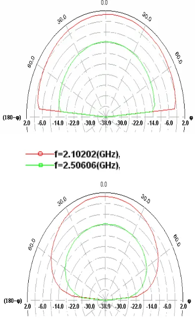
radiation pattern plot at two resonant frequencies in E and H planes of the six resonators. The radiation pattern at the two resonant frequencies is in the broadside direction.
[image:2.595.316.513.350.675.2] [image:2.595.111.226.358.501.2]
Optimizing the length and the coupling gap of the parasitic resonators results in the tri-band operation, the lengths of the 1st and 6th parasitic resonators are the same, they radiate at resonant frequencies closer to each other. The lengths of the 2nd and 5th parasitic resonators are increased along with increasing the gap width as compared to that of the dual configuration to reduce the coupling between the resonances. This results in the separation of the individual resonances, causing an additional frequency band to be obtained. The length of the 4th parasitic resonator is increased to bring its resonance frequency closer to that of the fed resonator. Table 2 gives the information of this configuration including lengths of resonators, the gap width, and resonant frequencies.
Table 2. Six resonators for triple frequency response (Єr = 4.3 , h = 1.59mm , tanδ = 0.02 , W = 7.68mm)
Lengths L (mm)
Gaps,S (mm)
fr1 GHz
fr2 GHz
fr3 (GHz ) L1 = 36
L2 = 34
L3(fed) = 36
L4 = 37.5
L5 = 35
L6= 36
S1 = 2.2
S2 = 0.2
S3 =
0.15 S4= 0.57
S5= 2.47
1.967 2.209 2.373
2.2. Configuration with seven resonators
for dual and tri-band operation:
The RMSA is further divided into seven resonators, where the 4th resonator is the centre feed. The lengths of the 3rd, 4th and 5th parasitic resonators are optimized with minimum gap
width for maximum coupling so that they resonate at same frequency. The resonating length and the gap width of the 2nd
and 6th parasitic resonators are increased to cancel their resonance, increasing the separation between the two bands. The resonating lengths of the 1st and 7th parasitic resonators are decreased to increase their resonance frequencies. The frequencies ratio increases to 1.24. This configuration has the resonant frequencies in (UMTS,1920-2170MHz) and (WLAN,2400-2483.5MHz) bands.For the triple frequency operation, the resonating lengths of the 2nd and 6th parasites are decreased so that they resonate to add one more frequency band. The lengths of the 1st and 7th parasitic resonators are the same but decreased to increase their resonant frequencies as compared with the dual frequency operation. The lengths of the 3rd and 5th elements are decreased to increase their resonant frequencies so that they resonate at frequencies closer to that of the driven element (4th element), and have sufficient separation between the two frequencies for the dual frequency operation. There is an increase in the bandwidth of the individual frequency bands.
2.3. Configuration with eight resonators for
dual and tri- band operation:
The eight resonators yield the frequencies ratio of 1.27 and as well increase the individual bandwidth of the resonant frequencies as compared with the six and the seven configurations. The resonating lengths of the 1st, 2nd, 7th and 8th parasites are almost the same but decreased from that of
the single RMSA, increasing the gap width which resonates at the same frequency. The resonating lengths of the parasites 3rd and 6th, also gap coupling are increased to contribute to the
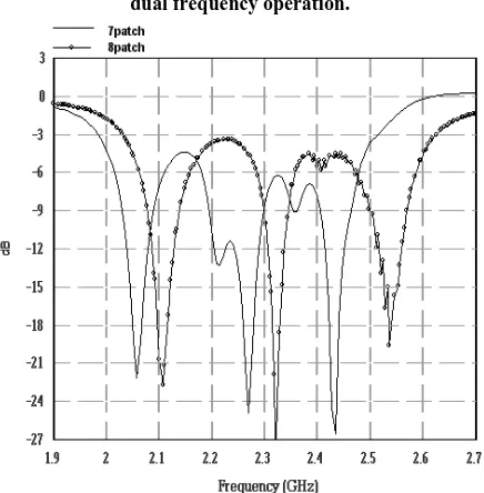
frequency band separation. The 4th resonator is fed at x = 7mm from the center with a co-axial connector. The gap width is minimized between the 4th and 5th resonators along with decreasing of the resonating length of the 5th parasite. The simulated return loss is shown in Fig. 5. The structure is fabricated using FR4 substrate with parameters, h = 1.59mm, Єr = 4.3, and tanδ = 0.02. The measured frequencies are fr1 =
2.11GHz and fr2 = 2.695GHz. The simulated frequencies are
fr1 = 2.1GHz and fr2 = 2.7GHz.
The resonating lengths of the parasites 1st, 2nd, 7th and 8th are increased so that the 2nd and 7th parasites resonate at the same frequency. When the difference between the resonating lengths of the resonators is less multiple resonances occur. Optimizing the resonating lengths of the parasites along with gap coupling results in tri-band operation. However, although the separation between resonances is increased, the increase in bandwidth becomes significantly less than the previous case. As can be seen from Fig. 6, the radiation pattern of all the three frequency bands are in broadside in E and H planes Fig. 7 shows the comparative plot of the return loss for seven and eight resonators for the tri-band operation. The simulation results yield an increase in the separation of the individual frequency bands with an increase in the number of resonators.
[image:3.595.321.519.319.494.2]Fig. 5. Measured and simulated S11 of eight resonators for dual frequency operation.
[image:3.595.320.538.521.743.2]
Fig. 6. Radiation pattern plot at three resonant frequencies in E and H planes of eight resonators.
2.4. Configuration with nine resonators for
dual and tri-band operation:
In this configuration, the parasitic resonators are all symmetrical about the 5th fed resonator. The length of the 4th parasitic resonator is reduced and the gap width between the 4th and 5th resonators is decreased so that they resonate at a frequency closer to each other. The gap width between the 4th
and 3rd parasitic resonators, along with resonating length of the 3rd and 6th parasites are increased to enhance the frequency separation. The resonating lengths of the 1st , 2nd ,7th and 9th are the same so that they resonate at the same frequency together with optimization of gap widths. The frequency ratio of 1.31 is obtained that is higher than the previous cases, but the bandwidth at individual band is reduced.
Tri-band frequency is obtained by increasing the resonating length of the 3rd and 8th parasites and decreasing the gap widths and the resonating length of 6th is reduced. This causes reduction in the coupling results in the tri-band operation. Simulations are performed with this configuration for the tri-band frequency operation. The configuration is fabricated using FR4 substrate with parameters, h = 1.59mm, Єr = 4.3, and tanδ = 0.02. The 5th element is fed at x = 8.2 from the
center. The measured resonance frequencies are fr1 = 2.07GHz, fr2 = 2.317GHz and fr3 = 2.549GHz, while the simulated resonant frequencies are fr1 = 2.062GHz, fr2 = 2.31GHz and fr3 = 2.46GHz. Fig. 7 shows the measured and simulated S11 of the nine resonators for the tri-band operation.
2.5. Configuration with ten resonators for
dual and tri- band operation:
As the number of resonators increases, the number of resonance also increases. The single RMSA is now divided into ten equi-width resonators The resonating lengths of the 1st, 3rd and 8th, 10th parasites are the same so that they resonate at frequencies closer to each other by varying the gap widths. While the resonating lengths and the gap width of the 2nd and 9th parasites are increased to decrease the resonant frequencies of these parasites, the resonating lengths of the 4th and 7th parasites are increased to decrease their resonant frequencies to suppress the other bands. The resonating length of the 6th
Fig. 8. Measured and simulated S11of nine resonators for tri-band operation.
parasite is decreased to increase its resonant frequency bring it closer to that of the fed element (5th element). The frequencies ratio is increased to 1.33. The bandwidth of the two frequency bands is reduced to 47MHz and 30MHz. For the triple band operation, the length of the 1st parasite is increased so that the 1st, 2nd and 3rd resonators resonate closer to each other. The resonant frequencies of the 8th, 9th and 10th parasites add up to resonate at the same frequency. The parasitic length of the 4th resonator is decreased to match its resonant frequency to that of the fed (5th resonator) resonator and that of the 6th resonator. The separation between the individual frequency bands is increased compared with that of the previous case.
2.6. Configuration with eleven resonators
for dual and tri- band operation:
[image:4.595.319.507.305.462.2]of the fed (6th resonator) resonator along with optimizing the gap widths.
Table 3: Comparisons of frequency ratios and bandwidth at dual frequency
No. of Reson-
ators
fr1 GHz
fr2 GHz
BW1 MHz
BW2 MHz
fr2/fr1
Six 2.085 2.53 43 43 1.21 Seven 1.998 2.474 51 47 1.24 Eight 2.10 2.70 57 60 1.27 Nine 2.078 2.722 52 40 1.31 Ten 2.062 2.759 47 30 1.33 Eleven 2.05 2.78 87 36 1.36 Twelve 2.033 2.845 32 35 1.40
The frequencies ratio with this configuration is increased to 1.36.
For the triple frequency operation, the resonating lengths of the 1st, 2nd and 3rd parasites are made closer to each other to have the first frequency band. Similarly, the resonating lengths of the 9th, 10th and 11th parasites yield the second frequency band and the 6th and 7th parasitic resonators resonate to yield the third frequency band. The resonating lengths of the 4th, 5th and 8th resonators are increased to decrease their resonant frequencies which provide separation between the bands.
2.7. Configuration with twelve resonator for
dual and tri- band operation:
In configuration with twelve strips, there can be a dual, tri as well as multi frequency operations. Only the dual and tri-frequency operations are investigated in this paper.
For the dual frequency operation, the resonating lengths of the 1st, 2nd, 3rd resonators are almost equal to that of the 10th, 11th and 12th respectively, as the parasites with the same lengths resonate at the same frequency. These six resonators along with the gap width variation resonate to result in one single frequency band. The resonating lengths of the 5th and
7th resonators are decreased to increase their resonant frequencies to match that of the fed (6th resonator) resonator in the second frequency band. The resonating lengths of the 4th, 8th, and 9th parasites are increased to decrease their resonant
frequencies that enhance the separation between the two resonant frequency bands. With this configuration, the maximum frequencies ratio achieved is 1.4. The bandwidths at individual frequency bands are just over 32MHz and 35MHz, respectively. As the difference between the lengths of the different elements becomes large, the separation between the resonances increases yielding a larger frequency ratio. Table 4 summarizes the comparisons of the frequency ratios and bandwidth at dual frequency up to twelve configurations. This configuration has resonant frequencies for (UMTS,1920-2170MHz) and (WIMAX,2.5-2.8GHz) bands.
Similarly, for triple frequency operation, the resonating lengths of the 8th and 9th resonators are decreased to have a frequency band between the two previous bands. The resonating lengths of the 10th and 11th parasite are increased to
decrease their resonant frequency and increase their separation. However, the separation between the resonances is larger for this configuration than the previous cases.
3. CONCLUSION
The nonradiating edges gap coupled microstrip antenna up to twelve resonators yields maximum frequency separation ratio of 1.4. At the same time, with increase in the number of parasitic resonators, the enhancement in the bandwidth of the individual frequency band is up to configuration of eight resonators. After that. the frequency ratio increases but the bandwidth reduces for dual frequency operation. Similarly for tri-band, it is observed that the separation between the individual band increases with increase in the number of resonators but increase in the bandwidth of the individual frequency band is insignificant. All these configurations are obtained by splitting a RMSA, and the resonating lengths were changed together with the gap widths. Further multiple frequency resonances may be obtained beyond the six resonating configuration by optimizing the resonating lengths of the parasitic resonators and the gap widths between them.
4. REFERENCES
[1] H. F. AbuTarboush, R. Nilavalan, K. M. Nasr, Raweshidy, D. Budimir and M. J. Alexander, “A Compact Printed Antenna for Multiband Wireless Applications” IEEE International Workshop on Antenna Technology (iWAT), Lisbon, Portugal
.
March 2010 pp 1-4.[2] Pramendra Tilanthe' P. C. Sharma
, “
Design of a single layer multiband microstrip square ring antenna” Applied Electromagnetics Conference (AEMC) Calcutta, India. Dec. 2009. pp. 1-4.[3] Yu-Jen Chi, Fu-Chiarng Chen
, “
Compact Printed Band Monopole Antenna for Mobile Devices”.Microwave Conference Proceedings (APMC),
Pacific, Yokohama, Japan. Dec.2010. pp.2216 – 2219.[4] W. X. Li, X. Liu, and S. Li, "Design of A Broadband and Multiband Planar Inverted-F Antenna," 2010 International conference on Communications and Mobile Computing, vol. 2,12-14 April 2010.
[5] A. A. Lotfi Neyestanak,Alex Danideh, Reza Sadeghifakhr “Compact size microstrip array mimo antenna operable in multiband”. June 2008 pp.158 – 161.
[6] G.Kumar and K.C.Gupta, “Nonradiating edges and four edges gap coupled wth multiple resonator, broadband Microstrip antennas”, IEEE Trans. Antennas Propagation 33 (1985), 173-178.
[7] G.Kumar and K.C.Gupta,“Broadband Microstrip antennas using additional resonators gap coupled to the radiating edges”, IEEE Trans. Antennas Propagation 32
(1986), 1375-1379.
[8] K. P. Ray ,G. Kumar, “ Multifrequency and broad band
hybrd-coupled circular microstrip antennas”, Electronic Letter 33 (1997), 437-438.
[9] K.P.Ray and G.Kumar, “Compact gapcoupled shorted 900 sectoral Microstrip antennas for broadband and dual band operations”, Microwave & Optical Tech. Letters 26 (2000),143-145.
![Fig.1, is designed to resonate at the frequency of 2GHz. The patch dimensions are calculated from formulas in [5] as follows: L = 35mm and W= 46.07mm](https://thumb-us.123doks.com/thumbv2/123dok_us/8099508.787321/1.595.381.475.390.515/designed-resonate-frequency-patch-dimensions-calculated-formulas-follows.webp)