Draft
Thermal Hydraulics Phenomena Identification and Ranking
Table (PIRT) for Advanced High Temperature Reactor (AHTR)
Prepared by:
Xiaodong Sun, Graydon L. Yoder Jr, Richard N. Christensen, Shanbin Shi, Hsun-Chia Lin, Xiao Wu, and Sheng Zhang
Performed Under:
Integrated Approach to Fluoride High Temperature Reactor
Technology and Licensing Challenges (FHR-IRP)
Project Number IRP-14-7829
Under DoE Contract Number DE-NE0008306
Technical Contact: David Holcomb
Federal Manager: Diana Li
Acknowledgements
This research is performed using funding received from the U.S. Department of Energy (DOE) Office of Nuclear Energy's Nuclear Energy University Programs.
i Thermal-hydraulics PIRT Report
Executive Summary
A team of researchers, led by the Georgia Institute of Technology (GT) and including major collaborators from The Ohio State University (OSU), Texas A&M University College Station (TAMU), Texas A&M University Kingsville (TAMU-K), Oak Ridge National Laboratory (ORNL), and AREVA, as well as international partners at University of Zagreb, Politecnico di Milano, and Shanghai Institute of Applied Physics (SINAP) contribute to investigation of technology gaps and licensing challenges of Fluoride salt-cooled High-temperature Reactor (FHR) under the current integrated research project (IRP). The most recent version of the Advanced High Temperature Reactor (AHTR), an FHR pre-conceptual design by ORNL, is selected as a candidate design for analysis and technology development.
An FHR thermal hydraulics Phenomena Identification and Ranking Table (PIRT) panel was assembled and met at OSU on May 24-26, 2016, which was organized by OSU and ORNL. The primary objective of the thermal hydraulics PIRT exercise is to identify key phenomena that require further detailed study and impose challenges on thermal hydraulics codes/methodologies to support AHTR licensing. The thermal hydraulics PIRT exercise provides guidance and insights in designing separate-effect and integral-effect tests for validation of thermal hydraulics codes. The thermal hydraulics PIRT panel consisted of fifteen experts specialized in salt reactor technologies, reactor thermal hydraulics, and code and methods development. Eleven out of the fifteen panelists were voting members while all the panelists actively participated during this PIRT panel meeting. Some student observers from GT, University of California-Berkeley, and OSU also attended this thermal hydraulics PIRT exercise.
ii Thermal-hydraulics PIRT Report
Table of Contents
Executive Summary ... i
List of Figures ...iv
List of Tables ... v
List of Abbreviations ...vi
1. Introduction ... 1
1.1. Overview ... 1
1.2. Report Organization ... 2
2. Overview of the PIRT Process ... 2
2.1. Background ... 2
2.2. Thermal Hydraulics PIRT Panelist ... 2
2.3. Thermal Hydraulics PIRT Exercise Process ... 3
2.3.1. Step 1: Define the Issue ... 4
2.3.2. Step 2: Define the Specific Objectives ... 4
2.3.3. Step 3: Define the Hardware and Scenario ... 4
2.3.4. Step 4: Define the Evaluation Criterion ... 4
2.3.5. Step 5: Identify, Compile, and Review the Current Knowledge Base ... 5
2.3.6. Step 6: Identify Plausible Phenomena ... 5
2.3.7. Step 7: Develop Importance Ranking ... 6
2.3.8. Step 8: Assess Knowledge Level ... 6
2.3.9. Step 9: Document PIRT Results ... 7
3. Introduction of AHTR ... 7
3.1. General Overview of the AHTR Plant Design ... 8
3.2. AHTR Neutronics Design ... 10
3.3. AHTR Thermal Hydraulics Design ... 11
3.3.1. Reactor Vessel ... 11
3.3.2. Reactor Core ... 13
3.3.3. Fuel Assembly ... 15
3.4. Reactor Coolant Systems ... 16
3.4.1 Primary Loop and Intermediate Loop ... 17
3.5. Reactor Safety Systems ... 18
3.5.1. DRACS Cooling System ... 18
iii Thermal-hydraulics PIRT Report
3.5.3. Reactor Cavity Cooling System ... 20
4. PIRT for the Event of Station Blackout ... 21
4.1. Definition of the Event ... 21
4.2. Proposed FOM of the Event... 21
4.3. Modeling the Event and Path Forward ... 22
4.4. PIRT for Station Blackout ... 23
5. PIRT for the Event of Simultaneous Withdrawal of All Control Rods... 50
5.1. Definition of the Event ... 50
5.2. Proposed FOM of the Event... 50
5.3. Modeling the Event and Path Forward ... 51
5.4. PIRT for Simultaneous Withdrawal of All Control Rods ... 52
6. Summary of Thermal Hydraulics PIRT Panel ... 78
iv Thermal-hydraulics PIRT Report
List of Figures
Figure 1. AHTR heat transfer paths (Varma et al., 2012) ... 9
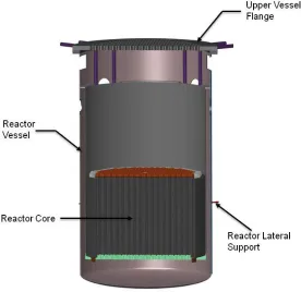
Figure 2. Sectional view of the AHTR reactor vessel (Varma et al., 2012) ... 12
Figure 3. Top flange of the AHTR reactor vessel (Varma et al., 2012) ... 13
Figure 4. Cross-sectional view of the reactor core (Varma et al., 2012) ... 14
Figure 5. Cross-sectional view of the reactor vessel (Varma et al., 2012) ... 14
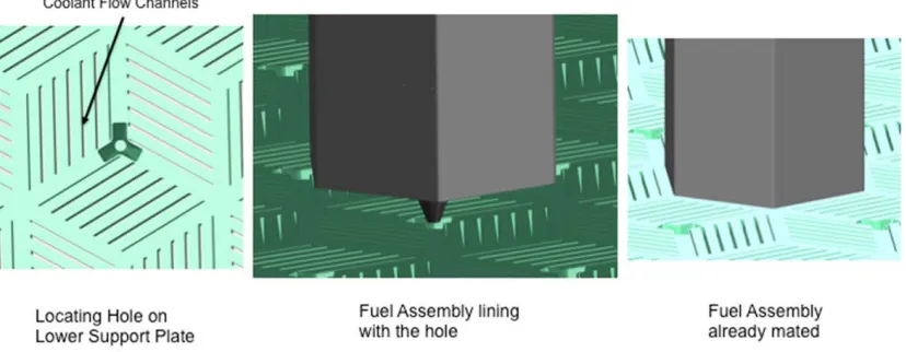
Figure 6. AHTR lower support plate (Varma et al., 2012) ... 15
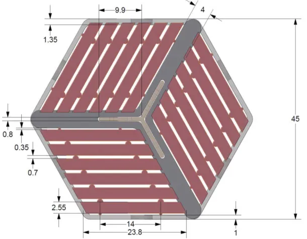
Figure 7. Cross section of the fuel assembly, Unit: cm (Varma et al., 2012) ... 16
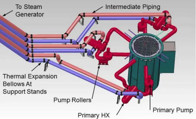
Figure 8. AHTR primary and intermediate cooling loops (Varma et al., 2012) ... 17
v Thermal-hydraulics PIRT Report
List of Tables
Table 1. A list of initially proposed scenarios and FOM for discussion ... 2
Table 2. Thermal hydraulics PIRT exercise panelists and organization ... 3
Table 3. Phenomena importance ranking and rationale (Ball et al., 2008) ... 6
Table 4. Knowledge level ranking and rationale (Ball et al., 2008) ... 7
Table 5. Determination of phenomena for further consideration ... 7
Table 6. AHTR general design parameters (Varma et al., 2012) ... 10
Table 7. Main refined AHTR neutronics design characteristics (Varma et al., 2012) .... 11
Table 8. AHTR reactor vessel design parameters (Varma et al., 2012) ... 12
Table 9. Geometric parameters of the AHTR reactor core (Varma et al., 2012) ... 15
Table 10. Geometric parameters of the AHTR fuel assembly (Varma et al., 2012) ... 16
Table 11. P-IHX design parameters and coolant thermal properties (Wang et al., 2015) ... 18
Table 12. P-IHX design (Wang et al., 2015) ... 18
Table 13. Preliminary design parameters of DHX (Wang et al., 2015) ... 19
Table 14. Preliminary design parameters of NDHX (Wang et al., 2015) ... 20
Table 15. Station blackout PIRT chart - Core/Fuel ... 23
Table 16. Station blackout PIRT chart - Core/Primary coolant flow ... 28
Table 17. Station blackout PIRT chart - Vessel ... 32
Table 18. Station blackout PIRT chart - Cavity ... 37
Table 19. Station blackout PIRT chart - Primary loop... 39
Table 20. Station blackout PIRT chart - Intermediate loop ... 42
Table 21. Station blackout PIRT chart - Power cycle ... 45
Table 22. Station blackout PIRT chart – DRACS ... 46
Table 23. Simultaneous withdrawal of all control rods PIRT chart -Core/Fuel ... 52
Table 24. Simultaneous withdrawal of all control rods PIRT chart -Core/Primary coolant flow ... 58
Table 25. Simultaneous withdrawal of all control rods PIRT chart - Vessel ... 62
Table 26. Simultaneous withdrawal of all control rods PIRT chart - Cavity ... 66
Table 27. Simultaneous withdrawal of all control rods PIRT chart – Primary loop ... 68
Table 28. Simultaneous withdrawal of all control rods PIRT chart – Intermediate loop . 72 Table 29. Simultaneous withdrawal of all control rods PIRT chart – Power cycle ... 75
vi Thermal-hydraulics PIRT Report
List of Abbreviations
AHTR C-C
CFD CHM DHX DOE DRACS FHR FOM IRP I-PHX LOCA MSRE NDHX ORNL OSU P-IHX PIRT TMSR TRISO V&V
Advanced High Temperature Reactor Carbon-Carbon
Computational Fluid Dynamics Carbon to Heavy Metal
DRACS Heat Exchanger U.S. Department of Energy
Direct Reactor Auxiliary Cooling System Fluoride High-Temperature Reactor Figure of Merit
Integrated Research Project
Intermediate to Power Loop Heat Exchanger Loss of Coolant Accident
Molten Salt Reactor Experiment Natural Draft Heat Exchanger Oak Ridge National Laboratory The Ohio State University
Primary to Intermediate Heat Exchanger Phenomena Identification and Ranking Table Thorium Molten Salt Reactor Energy System Tristructural-Isotropic
1.
Introduction
1.1. Overview
Fluoride-salt-cooled High-temperature Reactor (FHR) is one of the advanced reactor designs that combines improved technologies including low-pressure fluoride salt coolant, coated particle fuel (TRISO particles), Brayton power cycles, and passive safety systems. FHRs obtain several advantages including increased efficiency, low operation pressure, high core power density and high safety feature (Forsberg, 2005; Bardet et al., 2008). The Advanced High-Temperature Reactor (AHTR) is a FHR design concept proposed by Oak Ridge National Laboratory (ORNL). This report documents a thermal hydraulics Phenomena Identification and Ranking Table (PIRT) exercise for AHTR. The thermal hydraulics PIRT exercise was organized by The Ohio State University (OSU) and ORNL.
The primary objective of the thermal hydraulics PIRT exercise panel was to identify key phenomena requiring further detailed study and requirements on thermal hydraulics codes/methodologies to support AHTR licensing. The PIRT process identifies and ranks safety relevant phenomena that impact the fidelity of thermal hydraulics analysis for AHTR, and determines needed new databases, modeling, and detailed analysis to validate simulation tools and methods. In addition, PIRT provides guidance and insights in designing separate-effect and integral-effect experimental programs for validation of thermal hydraulics codes. A two and a half day thermal hydraulics PIRT panel workshop was held at the OSU from May 24 to 26, 2016. The thermal hydraulics PIRT panel consisted of fifteen experts specialized in salt reactor technologies, reactor thermal hydraulics, code and method development. Some student observers from GT, University of California-Berkeley, and OSU also attended this thermal hydraulics PIRT exercise.
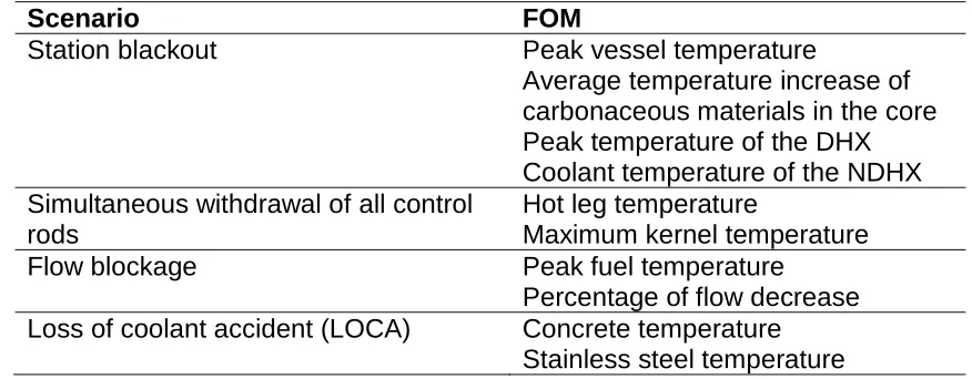
Table 1. A list of initially proposed scenarios and FOM for discussion
Scenario FOM
Station blackout Peak vessel temperature
Average temperature increase of carbonaceous materials in the core Peak temperature of the DHX Coolant temperature of the NDHX Simultaneous withdrawal of all control
rods
Hot leg temperature
Maximum kernel temperature
Flow blockage Peak fuel temperature
Percentage of flow decrease Loss of coolant accident (LOCA) Concrete temperature
Stainless steel temperature
1.2. Report Organization
A detailed discussion of the thermal hydraulics PIRT exercise process, including thermal hydraulics PIRT panelists, scenario description, etc., is given in Chapter 2. The thermal hydraulics PIRT during the meeting were categorized based on region of the reactor, including reactor core, vessel, cavity, primary loops, intermediate loops and Direct Reactor Auxiliary Cooling System (DRACS). Therefore, the AHTR thermal hydraulics design is reviewed in Chapter 3. Chapters 4 and 5 provide the information, such as phenomena identification and ranking, knowledge level ranking, the path forward, etc., for the events of station blackout and simultaneous withdrawal of all control rods, respectively. Chapter 6 summarizes the phenomena which need further work and research for FHR analysis to support of reactor licensing and the verification and validation (V&V) of thermal hydraulics system-level analysis codes and computational fluid dynamics (CFD) simulation tools for FHRs.
2.
Overview of the PIRT Process
2.1. Background
The thermal hydraulics PIRT exercise is an expert elicitation process with the phenomena ranking tables as the final output. The PIRT approach has been utilized in the nuclear industry for new reactor designs. The U.S. NRC developed the PIRT process for the next generation nuclear plant (Ball et al., 2008), which is beneficial for developing the AHTR thermal hydraulics PIRT.
2.2. Thermal Hydraulics PIRT Panelist
observers, including Pietro Avigni from Georgia Institute of Technology, Nicholas Brown from Oak Ridge National Laboratory, James Kendrick and Xin Wang from University of California Berkeley, Chong Zhou from Shanghai Institute of Applied Physics, and Hsun-Chia Lin, Shanbin Shi, Xiao Wu, Junlian Yin, Sheng Zhang and Xiaoqin Zhang from The Ohio State University. David Diamond led the thermal hydraulics PIRT panel discussions and acted as the facilitator for the process.
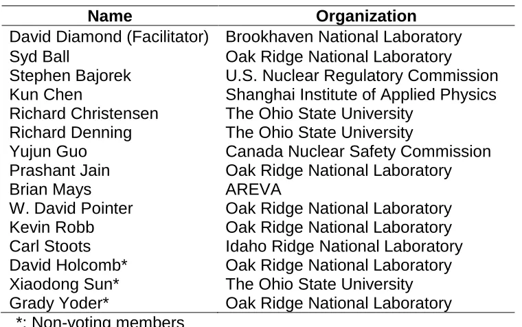
Table 2. Thermal hydraulics PIRT exercise panelists and organization
Name Organization
David Diamond (Facilitator) Brookhaven National Laboratory
Syd Ball Oak Ridge National Laboratory
Stephen Bajorek U.S. Nuclear Regulatory Commission
Kun Chen Shanghai Institute of Applied Physics
Richard Christensen The Ohio State University Richard Denning The Ohio State University
Yujun Guo Canada Nuclear Safety Commission
Prashant Jain Oak Ridge National Laboratory
Brian Mays AREVA
W. David Pointer Oak Ridge National Laboratory
Kevin Robb Oak Ridge National Laboratory
Carl Stoots Idaho Ridge National Laboratory
David Holcomb* Xiaodong Sun* Grady Yoder*
Oak Ridge National Laboratory The Ohio State University Oak Ridge National Laboratory *: Non-voting members
2.3. Thermal Hydraulics PIRT Exercise Process
The panelists were first provided with the following three introductory presentations:
• “The PIRT Process-Application to FHR Thermal Hydraulics” by David Diamond;
• “Review of Advanced High-Temperature Reactor (AHTR) Thermal Hydraulic Design” by Hsun-Chia Lin;
• “Summary of the White Paper prepared for FHR Thermal Hydraulics PIRT Panel” by Xiaodong Sun.
Following the introduction, the panelists discussed AHTR design issues and finalized scenarios of interest in AHTR to be discussed by the panel. The panelists then identified and ranked phenomena in each scenario. PIRT panelists finally reviewed and commented on the established phenomena ranking tables.
A detailed PIRT consists of the following nine steps (Ball et al., 2008): Step 1: Define the issue that is driving the need for a PIRT; Step 2: Define the specific objectives for the PIRT;
Step 5: Identify, compile, and review the current knowledge base; Step 6: Identify plausible phenomena, that is, PIRT elements; Step 7: Develop importance ranking for phenomena;
Step 8: Assess knowledge level for phenomena; and Step 9: Document PIRT results.
2.3.1. Step 1: Define the Issue
The objective of this step is to define the issue for AHTR future licensing applications. Issues related to AHTR safety should be identified. The definition may start with safety goals and descend to a consideration of important physical processes.
2.3.2. Step 2: Define the Specific Objectives
The objective of the thermal hydraulics PIRT exercise panel was to determine the important phenomena that impact the fidelity of thermal hydraulics analysis for the AHTR and determine where new databases, modeling, and detailed analysis need to be performed to validate computer codes and methods. In addition, it also provides guidance in establishing the requirements for separate-effects and integral-effects experimental programs in support of the AHTR licensing.
2.3.3. Step 3: Define the Hardware and Scenario
The AHTR design is the subject of this PIRT exercise. Four scenarios of the AHTR, including station blackout, simultaneous withdrawal of all control rods, reactor core flow blockage, and loss of coolant accident (LOCA) were proposed by the panelist. However, due to the limited time available (two and a half days), two scenarios, station blackout and simultaneous withdrawal of all control rods were selected for detailed discussion.
2.3.4. Step 4: Define the Evaluation Criterion
FOM defines the evaluation criterion. Since FOM depend on the scenario, each scenario has different FOM.
For the event of station blackout, the four FOM identified were:
• FOM1: Peak vessel temperature
• FOM2: Coolant temperature of the natural draft heat exchanger (NDHX)
• FOM3: Peak temperature of the DRACS heat exchanger (DHX)
• FOM4: Average temperature increase of carbonaceous materials in the core
DHX is selected as a FOM for the event of station blackout because it affects DRACS cooling performance by influencing the integrity of the DHX. Average temperature increase of carbonaceous materials in the core is selected as a FOM for the event of station blackout because it characterizes stored energy in carbonaceous materials which may delay and reduce vessel temperature increase. Temperature increase in the carbonaceous materials will also lead to potential tritium release. Furthermore, the amount of tritium released also depends on the original amount of tritium retained in carbonaceous materials.
For the event of simultaneous withdrawal of all control rods, the two FOM identified were:
• FOM1: Hot leg temperature
• FOM2: Maximum kernel temperature
When all control rods are withdrawn at one time, a positive reactivity is introduced making the reactor supercritical. Although the primary pumps are operating, the coolant temperature may still increase significantly. The hot leg temperature is the maximum temperature of the entire primary loop; it may exceed the structural material melting temperature and thus affects primary loop integrity. As for maximum kernel temperature, it was selected because of its significant influence on kernel integrity.
For reactor core flow blockage, two FOM identified were:
• FOM1: Percentage of flow decrease
• FOM2: Peak fuel temperature
Under reactor core flow blockage condition, temperature increase of blocked assemblies depends on the percentage of flow decrease. Therefore, the percentage of flow decrease was selected as a FOM for reactor core flow blockage. For the second FOM, the peak fuel temperature has a large effect on fuel integrity.
For LOCA, two FOM identified were:
• FOM1: Concrete temperature
• FOM2: Stainless steel temperature
Concrete temperature was selected as a FOM for LOCA because it affects concrete integrity. Stainless steel temperature was selected as a FOM because that its temperature affects integrity of structure material such as guard vessel.
2.3.5. Step 5: Identify, Compile, and Review the Current Knowledge Base
PIRT Panel members reviewed the thermal hydraulics whitepaper and relevant references. In addition, presentations at the meeting were beneficial for panelists to develop an understanding of current knowledge base related with AHTR technologies.
Systems and components in AHTR were defined and classified by panelists as follows,
• Core: fuel, primary coolant
• Vessel/internals/cavity: upper plenum, lower plenum, fluidic diode, reactor vessel, cavity
• Primary loop: pump, piping, primary to intermediate heat exchanger (P-IHX)
• Intermediate loop: pump, piping, P-IHX, intermediate to power loop heat exchanger (I-PHX)
• Power conversion loop: I-PHX
• DRACS: piping, DHX, NDHX, DRACS salt, chimney
Phenomena for each scenario was identified, defined, and documented in Chapter 4 and 5.
2.3.7. Step 7: Develop Importance Ranking
After the phenomena had been identified, phenomena importance ranking level was decided by panelists based on its effects on the FOMs. Table 3 shows the phenomena importance ranking and rationale. Under consideration of its importance to each FOM in a specific scenario, panelists then voted for each phenomenon, and phenomena importance ranking is then solidified by averaging the votes.
Voting members classified each phenomenon as having a large effect (High), moderate effect (Medium), or small effect (Low) on one FOM in a specific scenario. Votes for High (H), Medium (M), and Low (L) importance were assigned numerical scores of 8, 5, and 2, respectively. If the average was larger than 6.5, the importance was assigned as High. If the average was between 3.5 and 6.5, the importance was assigned as Medium. If the average was below 3.5, the importance was set to Low.
Table 3. Phenomena importance ranking and rationale (Ball et al., 2008)
Ranking Description
High (H) Significant or dominant influence on FOM Medium (M) Moderate influence on FOM
Low (L) Small influence on FOM (including the possibility that the phenomena is not present or possible)
2.3.8. Step 8: Assess Knowledge Level
Table 4. Knowledge level ranking and rationale (Ball et al., 2008)
Ranking Description
Known (K) Phenomenon is well understood and can be accurately modeled
Partially Known (P)
Phenomenon is understood, however, can only be modeled with moderate uncertainty
Unknown (U)
Phenomenon is not well understood. Modeling is current either not possible or is possible only with large uncertainty
[image:14.612.129.479.451.539.2]After phenomena importance ranking and knowledge level ranking, we then moved to determine the phenomena that need further consideration. Table 5 shows the phenomena determination rules for further consideration. As can be seen from the table, phenomena under three combinations of importance ranking and knowledge level require further consideration: 1) the importance ranking is high (H) and knowledge level is partially known (P), 2) the importance ranking is high (H) and knowledge level is unknown (U), and 3) the importance ranking is medium (M) and knowledge level is unknown (U).
Table 5. Determination of phenomena for further consideration
Importance Ranking (IR)
H M L
K
P YES
U YES YES
2.3.9. Step 9: Document PIRT Results
PIRT results, including phenomena definition, importance ranking, knowledge level ranking, rationale for all rankings, next steps for phenomena that need further consideration and prioritization of next steps should be documented in this step.
3.
Introduction of AHTR
selected as the reference design for the present thermal hydraulics PIRT study. In the subsequent sections, a general overview of the ORNL AHTR conceptual design will be presented, focusing on the thermal hydraulics related design including core, reactor vessel, reactor coolant systems and reactor safety system in the AHTR. The information presented hereafter is mainly based on the partially optimized AHTR design report by Varma et al. (2012), supplemented by an earlier AHTR design report by Holcomb et al. (2011).
3.1. General Overview of the AHTR Plant Design
The AHTR is an FHR design concept with a thermal power output of 3400 MW. The AHTR consists of three primary loops and three intermediate loops that are coupled to a supercritical water power cycle. The molten salt FLiBe (2LiF-BeF2), which was extensively investigated in the Molten Salt Reactor Experiment (MSRE) project, is adopted as the AHTR primary coolant, while a mixture of KF and ZrF4 featuring a low melting point is used as the intermediate coolant. The AHTR relies on three DRACS loops for passive decay heat removal. The DRACS also employs KF-ZrF4 as the coolant in the DRACS secondary circuit that is coupled to the ultimate heat sink, the ambient air.
Figure 1. AHTR heat transfer paths (Varma et al., 2012)
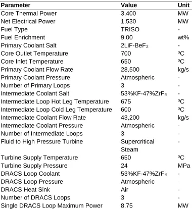
Table 6. AHTR general design parameters (Varma et al., 2012)
Parameter Value Unit
Core Thermal Power 3,400 MW
Net Electrical Power 1,530 MW
Fuel Type TRISO -
Fuel Enrichment 9.00 wt%
Primary Coolant Salt 2LiF-BeF2 -
Core Outlet Temperature 700 oC
Core Inlet Temperature 650 oC
Primary Coolant Flow Rate 28,500 kg/s
Primary Coolant Pressure Atmospheric -
Number of Primary Loops 3 -
Intermediate Coolant Salt 53%KF-47%ZrF4 -
Intermediate Loop Hot Leg Temperature 675 oC
Intermediate Loop Cold Leg Temperature 600 oC
Intermediate Coolant Flow Rate 43,200 kg/s
Intermediate Coolant Pressure Atmospheric -
Number of Intermediate Loops 3 -
Fluid to High Pressure Turbine Supercritical Steam
-
Turbine Supply Temperature 650 oC
Turbine Supply Pressure 24 MPa
DRACS Loop Coolant 53%KF-47%ZrF4 -
DRACS Loop Pressure Atmospheric -
DRACS Heat Sink Air -
Number of DRACS Loops 3 -
Single DRACS Loop Maximum Power 8.75 MW
3.2. AHTR Neutronics Design
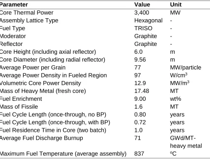
Table 7. Main refined AHTR neutronics design characteristics (Varma et al., 2012)
Parameter Value Unit
Core Thermal Power 3,400 MW
Assembly Lattice Type Hexagonal -
Fuel Type TRISO -
Moderator Graphite -
Reflector Graphite -
Core Height (including axial reflector) 6.0 m
Core Diameter (including radial reflector) 9.56 m
Average Power per Grain 77 MW/particle
Average Power Density in Fueled Region 97 W/cm3
Volumetric Core Power Density 12.9 MW/m3
Mass of Heavy Metal (fresh core) 17.48 MT
Fuel Enrichment 9.00 wt%
Mass of Fissile 1.6 MT
Fuel Cycle Length (once-through, no BP) 0.80 years
Fuel Cycle Length (once-through, with BP) 0.72 years
Fuel Residence Time in Core (two batch) 1.0 years
Average Fuel Discharge Burnup 71
GWd/MT-heavy metal Maximum Fuel Temperature (average assembly) 837 oC
3.3. AHTR Thermal Hydraulics Design
In this section, the design specifications and parameters of the AHTR components that are related to the thermal hydraulics PIRT exercises are reviewed.
3.3.1. Reactor Vessel
Table 8. AHTR reactor vessel design parameters (Varma et al., 2012)
Parameter Value Unit
Exterior Vessel Diameter 10.5 m
Vessel Height 19.1 m
Primary Salt Depth Above Upper Support Plate 7.15 m
Primary Piping Interior Diameter 1.24 m
Primary Salt Mass 3,076 MT
Number of DRACS Loops 3 -
Core Barrel Material C-C Composite -
Vessel and Primary Piping Material Incoloy 800H
w/Hastelloy N Lining -
Number of Fuel Assemblies 252 -
Upper and Lower Core Support Plates SiC-SiC Composite -
Figure 2. Sectional view of the AHTR reactor vessel (Varma et al., 2012)
cm. The flange consists of a truss structure fabricated by two 1.5-cm thick stainless-steel top and bottom plates to reduce weight.
Figure 3. Top flange of the AHTR reactor vessel (Varma et al., 2012)
3.3.2. Reactor Core
Figure 4. Cross-sectional view of the reactor core (Varma et al., 2012)
The lower core support plate provides support to the reactor core. This plate has a honeycomb structure made from 35-cm thick SiC-SiC composite pieces. Channels are fabricated in the lower support plate to direct the flow into the fuel assemblies, as shown in Figure 6. In addition, indexing holes and guides are fabricated to assist with the alignment of the fuel assemblies, which have a gap distance of 1.75 cm with the neighboring fuel assemblies. The main function of the upper core support plate is to align and hold the fuel assemblies in place against the upward flowing salt during reactor operation. The upper support plate is made from the same material and has the same thickness as the lower support plate. The geometric parameters of the AHTR reactor core are summarized in Table 9.
[image:22.612.101.515.226.387.2]Figure 6. AHTR lower support plate (Varma et al., 2012)
Table 9. Geometric parameters of the AHTR reactor core (Varma et al., 2012)
Parameter Value Unit
Equivalent Core OD (fueled region) 7.81 m Equivalent Replaceable Reflector OD 8.69 m Equivalent Permanent Reflector OD 9.56 m
Boron Carbide Layer OD 9.58 m
Barrel OD 9.62 m
Core Height (fueled region) 5.5 m
Core Height (including axial reflector) 6.0 m
Vessel OD 10.50 m
3.3.3. Fuel Assembly
box wall and Y-structure wall, the flow channel is 0.35 cm thick. The gap between two neighboring fuel assemblies is 1.75 cm thick, resulting in a fuel assembly pitch of 46.75 cm. The geometric parameters of the fuel assembly can be found in Table 10.
[image:23.612.150.455.129.366.2]Figure 7. Cross section of the fuel assembly, Unit: cm (Varma et al., 2012)
Table 10. Geometric parameters of the AHTR fuel assembly (Varma et al., 2012)
Parameter Value Unit
Total Height 6.0 m
Fueled Region Height 5.5 m
Fuel Assembly Pitch 46.75 cm
Outer Apothem 22.5 cm
Channel Box Wall Thickness 1 cm
Y-structure Thickness 4 cm
Coolant Thickness between Plates 0.7 cm
Coolant Thickness between Plate and Wall 0.35 cm
Fuel Plate Thickness 2.55 cm
Number of Fuel Plates 18 -
3.4. Reactor Coolant Systems
ORNL reference reports, detailed designs of the cooling systems are not provided. In the study of thermal hydraulics analysis of the AHTR by Wang et al., (2015), some preliminary design parameters of the AHTR cooling systems are available and thus adopted in this white paper as a reference.
3.4.1 Primary Loop and Intermediate Loop
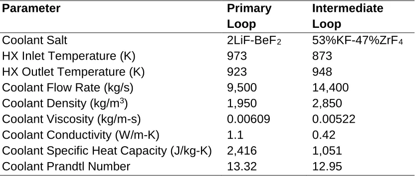
During reactor normal operation, primary heat removal is achieved through three primary coolant loops, consisting of the primary piping, the P-IHX, and the primary salt pump. The three primary loops are coupled with three intermediate loops through the P-IHX’s, as shown in Figure 8. The piping in both loops has an inner diameter of 1.24 m and are made from Hastelloy N (Varma et al., 2012). The hot leg length and cold leg length are assumed to be 15.75 and 9.37 m, respectively (Wang et al., 2015).
Figure 8. AHTR primary and intermediate cooling loops (Varma et al., 2012)
[image:24.612.141.471.260.461.2]Table 11. P-IHX design parameters and coolant thermal properties (Wang et al., 2015)
Parameter Primary
Loop
Intermediate Loop
Coolant Salt 2LiF-BeF2 53%KF-47%ZrF4
HX Inlet Temperature (K) 973 873
HX Outlet Temperature (K) 923 948
Coolant Flow Rate (kg/s) 9,500 14,400
Coolant Density (kg/m3) 1,950 2,850
Coolant Viscosity (kg/m-s) 0.00609 0.00522
Coolant Conductivity (W/m-K) 1.1 0.42
Coolant Specific Heat Capacity (J/kg-K) 2,416 1,051
Coolant Prandtl Number 13.32 12.95
Table 12. P-IHX design (Wang et al., 2015)
Parameter Shell Side Tube Side
Loop Allocation Primary Intermediate
Coolant Salt 2LiF-BeF2 53%KF-47%ZrF4
Tube Length (m) - 20.0
Tube ID (cm) - 1.9735
Tube Wall Thickness (cm) - 0.1245
Number of Tubes - 18,000
Tube Pitch (cm) - 1.5 OD
Tube Arrangement - Square array
Shell Inside Diameter (m) 5.18 -
Baffle Spacing (m) 2.0 -
Baffle Cut 25% -
3.5. Reactor Safety Systems
3.5.1. DRACS Cooling System
[image:25.612.101.510.309.504.2]Figure 9. Schematic of the DRACS (Varma et al., 2012)
The DRACS loops are coupled with the AHTR primary salt system through the DHX’s that are submerged in the reactor pool. The preliminary design parameters of the DHX by Wang et al., (2015) are summarized in Table 13. The DHX is connected to the NDHX through piping with an inner diameter of 0.4 m (Wang et al., 2015). The NDHX is at a higher elevation than the DHX by a minimum of 16 m (Varma et al., 2012). The lengths of the cold leg and hot leg of the DRACS loop are both 35 m. The DRACS cooling tower of an annular design houses the NDHX and has a height of 12.92 m, inner radius of 2.5 m and outer radius of 3 m (Wang et al., 2015). The preliminary design parameters of the NDHX are summarized in Table 14.
Table 13. Preliminary design parameters of DHX (Wang et al., 2015)
DHX Design Shell and Tube
Tube Arrangement Staggered
Primary Side Shell
DRACS Side Tube
Number of Tubes 1,078
Number of Tube Rows 98
Number of Tube Passes 3
Tube Length (m) 3.6
Tube OD (cm) 2.54
Tube Wall Thickness (cm) 0.1651
[image:26.612.178.434.529.707.2]Table 14. Preliminary design parameters of NDHX (Wang et al., 2015)
NDHX Design Horizontal Fined
Tubes
Tube Arrangement Inline
DRACS Loop Side Tube
Number of Tubes 200
Number of Tube Rows 4
Number of Tube Passes 1
Tube Length (m) 4.0
Tube OD (cm) 2.54
Tube Wall Thickness (cm) 0.1651
Fin Height (cm) 2.54
Fin Spacing (cm) 1.5
3.5.2. Maintenance Cooling System
In addition to the DRACS cooling system, the maintenance cooling system also participates in heat removal from the reactor when the reactor and the primary cooling system are shut down for planned maintenance, as shown in Figure 9. The maintenance heat exchanger that is submerged in the reactor pool is the same as the DHX, but the salt flow through the maintenance heat exchanger is circulated by a pump. Also, in the salt-to-air heat exchanger, forced air circulation flow instead of natural convection flow is provided from a fan. Due to these differences, the heat removal capability of the maintenance cooling system is significantly larger than that of the DRACS system, namely, 5% of the nominal core power or 170 MWth.
3.5.3. Reactor Cavity Cooling System
4.
PIRT for the Event of Station Blackout
This section introduces the event of station blackout, including the event definition, the proposed FOM and reasons for selecting these FOM, and the current status of modeling of the event. Based on the significance of the identified phenomena and current research and knowledge status, path forward to better model the event is proposed. The final PIRT results for this event are listed in Section 4.4.
4.1. Definition of the Event
A station blackout event is the total loss of all offsite and onsite alternating current (AC) power. Per design, when the external AC electrical power is lost, onsite emergency diesel generators will start working to provide AC electrical power for safe operations and accident recovery. However, when the diesel generators also fail, the nuclear power plant is then left in the station blackout event.
In the event of station blackout, the pumps will trip and coast down due to no electric power supply. Therefore, forced coolant circulations is gradually lost. As an emergence response, the reactor will scram. One major concern in such situations is the generation and removal of decay heat. Safety analysis shows that station blackout is a significant contributor to overall plant risk. For the AHTR design, the fuel and coolants have large thermal margins in normal operations before failure. However, even with the superior inherent safety features, station blackout is still an event worthwhile investigating into for the AHTR design.
4.2. Proposed FOM of the Event
The PIRT panel identified and ranked phenomena based on the following FOM:
1. Peak vessel temperature:
Under a station blackout, active cooling systems of the AHTR, such as the power conversion cycle loops and maintenance cooling system, are not available for heat removal from the reactor. After a reactor trip, DRACS cooling system can be launched and three DRACS loops takes out about 0.75% of nominal thermal power based on the AHTR design. Therefore, vessel temperature may increase dramatically and exceed its damage point if the heat removal rate keeps being less than the heat generation rate. That is the reason why peak vessel temperature is selected as an FOM for the event of station blackout.
2. Average temperature increase of carbonaceous materials in the core:
This FOM is selected because it characterizes the stored energy in carbonaceous materials, which may significantly delay and reduce the increase of vessel temperature. Temperature increase in carbonaceous materials will also lead to potential tritium release. However, the amount of tritium released also depends on the original amount of tritium retained in these carbonaceous materials.
Coolant in the NDHX may freeze due to the overcooling by the air in the natural draft chimney and thus reduces DRACS cooling performance. Therefore, this FOM is selected.
4. Peak temperature of the DHX:
Peak temperature of the DHX is selected as an FOM for the event of station blackout because it affects DRACS cooling performance due to the potential damage to the integrity of the DHX.
4.3. Modeling the Event and Path Forward
4.4. PIRT for Station Blackout
Table 15. Station blackout PIRT chart - Core/Fuel
System/ID: 1. Core (a) Fuel Phenomeno
n Definition
Figures of Merit (FOM) and Importance Level
Knowledge
Level Comments and Path Forward
Heat capacity of the
carbonaceous material
Heat capacity as a function of
temperature and
irradiation
Peak vessel temperature: M
Average temperature increase of
carbonaceous materials in the core: H
K
Comments:
1. After the reactor scrams, a portion of the captured tritium in carbonaceous materials will release to the salt with temperature increase. Tritium release rate depends on: a. Initial amount of captured tritium in
carbonaceous materials
b. Temperature difference before and after the reactor scram
2. Tritium retention in carbonaceous materials mainly depends on the temperature:
a. higher temperature results in lower tritium retention
b. Since temperature of the reflector is lower than that of the fuel, more tritium might be retained in the reflector than in the fuel carbonaceous materials
3. Tritium retention capability among different types of the carbonaceous differs greatly 4. Heat capacity of the carbonaceous
materials of different grades is well known
Path forward:
System/ID: 1. Core (a) Fuel Phenomeno
n Definition
Figures of Merit (FOM) and Importance Level
Knowledge
Level Comments and Path Forward
Thermal conductivity of the
carbonaceous materials
As a function of
temperature and
irradiation
Peak vessel
temperature: M P
Comments:
Part of the TRISO particles are made of the carbonaceous materials
Path forward:
Consult material scientists
Heat capacity of the fuel stripe
As a function of temperature and irradiation Peak vessel temperature: M Average temperature increase of the
carbonaceous materials in the core: H
K
Comments:
The fuel stripe here is included as a part of the carbonaceous materials
Path forward:
None. Based on the combined importance and knowledge level, this phenomenon does not require further exploration
Thermal conductivity of the fuel stripe
As a function of the
temperature and
irradiation
Peak vessel
temperature: M P
Comments:
Analysis for this phenomenon is similar to that for the thermal conductivity of the carbonaceous materials
Path forward:
System/ID: 1. Core (a) Fuel Phenomeno
n Definition
Figures of Merit (FOM) and Importance Level
Knowledge
Level Comments and Path Forward
Heat capacity of the fuel kernel
As a function of
temperature and
irradiation
Peak vessel
temperature: L -
Comments:
To study its effect on the vessel
temperature, the mass and heat capacity of the fuel kernel need to be considered. Therefore, overall heat capacity is defined asmcp
Path forward:
None. Based on the combined importance and knowledge level, this phenomenon does not require further exploration
Thermal conductivity of the fuel kernel
As a function of the
temperature and
irradiation
Peak vessel
temperature: L -
Comments:
The mass of the fuel kernel is small
Path forward:
System/ID: 1. Core (a) Fuel Phenomeno
n Definition
Figures of Merit (FOM) and Importance Level
Knowledge
Level Comments and Path Forward
Geometry of the fuel plate
Distortion due to irradiation
Peak vessel
temperature: M U
Comments:
1. Affects the size of the flow channels, pressure drop and heat transfer 2. Highly related to mixing of flow in the
plenums and therefore flow distribution 3. Generally, graphite first swells and then
shrinks under irradiation
4. Lack of knowledge. Panel not equipped to address this phenomenon
Path forward:
Consult material scientists. It is an issue less related to thermal hydraulics
Energy generation rate in the fuel kernel
Heat generation rate axially and
transversely (radially) due to
accumulation of the fission products and actinides at steady-state and decay power
Peak vessel
temperature: H K
Comments: None
Path forward:
System/ID: 1. Core (a) Fuel Phenomeno
n Definition
Figures of Merit (FOM) and Importance Level
Knowledge
Level Comments and Path Forward
Radiative
heat transfer Surface of the fuel plate
Peak vessel
temperature: L -
Comments: None
Path forward:
None. Based on the combined importance and knowledge level, this phenomenon does not require further exploration
Surface condition
Surface roughness, degradation or erosion
Peak vessel
temperature: M P
Comments:
1. Fuel kernels burn out fast. Fuel elements should be replaced before serious
deformation happens
2. Carbon surface obeys Young’s modulus 3. Corrosion could happen to carbon
Path forward:
Table 16. Station blackout PIRT chart - Core/Primary coolant flow
System/ID: 1 Core (b) Primary Coolant Flow
Phenomenon Definition Figures of Merit (FOM)
and Importance Level
Knowledge
Level Comments and Path Forward
Heat capacity of FLiBe
As a function of the
temperature
Peak vessel temperature:
H K
Comments: None
Path forward:
None. Based on the combined
importance and knowledge level, this phenomenon does not require further exploration
Thermal conductivity of FLiBe
As a function of the
temperature
Peak vessel temperature: H
P
Comments:
Review ongoing research at various institutes
Path forward:
Review current uncertainties in
measurements; understand sensitivities to those uncertainties
Viscosity of FLiBe
As a function of the
temperature
Peak vessel temperature:
H P
Comments:
Similar to the previous FLiBe thermal conductivity
Path forward:
System/ID: 1 Core (b) Primary Coolant Flow
Phenomenon Definition Figures of Merit (FOM)
and Importance Level
Knowledge
Level Comments and Path Forward
Core heat transfer coefficient Forced/ natural convection
Peak vessel temperature: M
Average temperature increase of the
carbonaceous materials in the core: M
P
Comments: None
Path forward:
Separate-effect tests for correlation development and validation
Optical properties Absorption and transmission as function of the temperature and wavelength
Peak vessel temperature:
L -
Comments:
1. Radiation heat transfer is much lower than convective heat transfer 2. FLiBe is transparent
Path forward:
None. Based on the combined
importance and knowledge level, this phenomenon does not require further exploration
Form loss coefficients
Entrance and exit loss coefficients as a function of the area ratio and Reynolds number
Peak vessel temperature:
M P
Comments:
Small change in the design could potentially lead to large difference
Path forward:
None. Based on the combined
System/ID: 1 Core (b) Primary Coolant Flow
Phenomenon Definition Figures of Merit (FOM)
and Importance Level
Knowledge
Level Comments and Path Forward
Wall friction
Taking into account spacer ridges on the fuel plates
Average temperature increase of the
carbonaceous materials in the core: H
P
Comments:
1. Similar to the surface condition 2. Affects local flow condition
(laminar or turbulent)
Path forward:
Needs scaled experimental data
Core flow asymmetry
Due to components in the vessel
Peak vessel temperature:
M U
Comments:
1. Typical situations of the asymmetry:
a. At least one DRACS is not working properly: either has flow through but no heat rejection, or no flow and the flow distribution in the core is changed;
b. One part of the vessel has higher temperature than the other parts. During normal operation, power generation is homogeneous
2. Needs calculation of the coolant mixing in the downcomer
Path forward:
1. Perform CFD calculations of the core, downcomer, lower plenum and upper plenum
System/ID: 1 Core (b) Primary Coolant Flow
Phenomenon Definition Figures of Merit (FOM)
and Importance Level
Knowledge
Level Comments and Path Forward
Bypass fraction
Intra-assembly flow
Peak vessel temperature:
L -
Comments:
Lower flow rate compared to that in core flow channels
Path forward:
1. Design needs to be solidified 2. Perform CFD analysis to
investigate the fuel plate swelling/distortion
Direct energy deposition
Direct heating of the coolant from fuel as a function of the axial and radial
position in the core for steady-state and decay loads
Peak vessel temperature: L
Average temperature increase of the
carbonaceous materials in the core: M
P
Comments:
Gamma spectrum is one of the direct energy deposition sources
Path forward:
None. Based on the combined
Table 17. Station blackout PIRT chart - Vessel
System/ID: 2(a). Vessel
Phenomenon Definition Figures of Merit (FOM)
and Importance Level
Knowledge
Level Comments and Path Forward
Upper plenum mixing
Pluming and stratification and impact on upper internal structure
Peak vessel temperature:
H U
Comments:
1. Needs modeling for:
a. Mixing and cross flow in this region
b. Heat transfer to upper plenum structural materials
2. Needs system analysis on thermal stratification
Path forward:
1. Perform CFD calculations of the lower plenum, upper plenum and downcomer
[image:39.792.80.723.101.351.2]System/ID: 2(a). Vessel
Phenomenon Definition Figures of Merit (FOM)
and Importance Level
Knowledge
Level Comments and Path Forward
Fluidic diodicity
Pressure loss as a function of flow direction and flow rate
Peak vessel temperature:
H P
Comments:
1. Affects core bypass flow,
circulation mass flow rate, DRACS performance, etc.
2. No reverse flow on the coolant side of DRACS, but reverse flow could happen on the primary side 3. Simulation and experimental
results obtained from
Low-Temperature DRACS test Facility, LTDF provide a reference
Path forward:
Continue investigation and research of the fluidic diodicity
Cover gas entrainment
Due to frothing at the free surface
Peak vessel temperature:
L -
Comments: None
Path forward:
None. Based on the combined
System/ID: 2(a). Vessel
Phenomenon Definition Figures of Merit (FOM)
and Importance Level
Knowledge
Level Comments and Path Forward
Thermal heat capacity of the vessel
To
determine heat transfer across the vessel wall
Peak vessel temperature:
L -
Comments:
The thin vessel wall leads to small thermal inertia
Path forward:
None. Based on the combined
importance and knowledge level, this phenomenon does not require further exploration
Thermal conductivity of the vessel
To
determine heat transfer across the vessel wall
Peak vessel temperature:
L -
Comments: None
Path forward:
None. Based on the combined
importance and knowledge level, this phenomenon does not require further exploration
Heat transfer to the upper plenum structures
Control rod drives etc. Guide tubes
Peak vessel temperature:
L -
Comments: None
Path forward:
None. Based on the combined
System/ID: 2(a). Vessel
Phenomenon Definition Figures of Merit (FOM)
and Importance Level
Knowledge
Level Comments and Path Forward
Heat transfer coefficient to the vessel wall
Natural/ Forced convection heat transfer coefficient (inside the vessel)
Peak vessel temperature:
M K
Comments:
Simple geometry and well known
Path forward:
None. Based on the combined
importance and knowledge level, this phenomenon does not require further exploration
Friction factor on the vessel wall in the downcomer
Downcomer pressure drop
Peak vessel temperature:
M K
Comments: None
Path forward:
None. Based on the combined
importance and knowledge level, this phenomenon does not require further exploration
Mixing in the lower plenum
From eight downcomer segments
Peak vessel temperature:
M U
Comments:
1. Similar to the situation in the upper plenum
2. The height of the lower plenum is smaller than that of the upper plenum
Path forward:
System/ID: 2(a). Vessel
Phenomenon Definition Figures of Merit (FOM)
and Importance Level
Knowledge
Level Comments and Path Forward
Heat transfer to the cover gas and vessel top flange
Radiative and
convective heat transfer
Peak vessel temperature:
M P
Comments:
1. The top flange has a large surface area
2. Core will be submerged in the salt while the decay heat keeps the salt molten. Therefore, the temperature of the top flange will not increase greatly
Path forward:
None. Based on the combined
Table 18. Station blackout PIRT chart - Cavity
System/ID: 2(b). Cavity
Phenomenon Definition Figure of Merits (FOMs)
and Importance Level
Knowledge
Level Comments and Path Forward
Thermal
properties of the insulation
Density, thermal conductivity and capacity
Peak vessel temperature:
L -
Comments:
1. Argon gap between vessel and insulation
2. Certain degree of thermal
expansion of the insulation has to be taken into consideration
3. Design has to be improved for easier attachment of the insulation to the guard vessel
Path forward:
None. Based on the combined importance and knowledge level, this phenomenon does not require further exploration
Heat transfer across vessel to the gas space
Net
resistance to heat transfer
Peak vessel temperature:
L -
Comments: None
Path forward:
[image:44.792.168.723.107.462.2]System/ID: 2(b). Cavity
Phenomenon Definition Figure of Merits (FOMs)
and Importance Level
Knowledge
Level Comments and Path Forward
Heat transfer across second gap to the concrete
Convection and radiation
Peak vessel temperature:
L -
Comments:
Reasons for the existence of argon gap:
a. To accommodate thermal expansion of the insulation, which is inside the guard vessel b. To allow robots with mirror to
get into the gap for vessel inspection. This is also the design base for the thickness of the argon gap
Path forward:
None. Based on the combined importance and knowledge level, this phenomenon does not require further exploration
Conduction in the concrete
Wall heat transfer and conductivity
Peak vessel temperature:
L -
Comments: None
Path forward:
[image:45.792.77.726.77.465.2]Table 19. Station blackout PIRT chart - Primary loop
System/ID: 3 Primary Loop
Phenomenon Definition Figures of Merit (FOM)
and Importance Level
Knowledge
Level Comments and Path Forward
Pump
performance
Relationship between driving force and flow rate, efficiency (vendor info), including coastdown (speed vs. time)
Peak vessel temperature:
L -
Comments:
Pump working condition is included in the initial conditions in modeling for all events
Path forward:
1. Conduct investigation on design and testing of pumps
2. Set pump requirements and share with vendors
3. Perform analysis that informs pump design inputs/parameters 4. Simple models are currently
available
Pump resistance or K factor
Pressure drop across the pump
Peak vessel temperature:
L -
Comments:
The pump functions as additional flow resistance when not working
Path forward:
None. Based on the combined
[image:46.792.72.730.114.465.2]System/ID: 3 Primary Loop
Phenomenon Definition Figures of Merit (FOM)
and Importance Level
Knowledge
Level Comments and Path Forward
Form loss in the loop
Pressure loss due to bends, fittings, valves, etc.
Peak vessel temperature:
L -
Comments: None
Path forward:
None. Based on the combined
importance and knowledge level, this phenomenon does not require further exploration
Wall friction in the loop
Function of the Reynolds number
Peak vessel temperature:
L -
Comments: None
Path forward:
None. Based on the combined
importance and knowledge level, this phenomenon does not require further exploration
P-IHX
performance
Heat transfer and pressure drop on the primary side
Peak vessel temperature:
L -
Comments: None
Path forward:
None. Based on the combined
System/ID: 3 Primary Loop
Phenomenon Definition Figures of Merit (FOM)
and Importance Level
Knowledge
Level Comments and Path Forward
Heat loss through and from, thermal inertia of piping
Through intact insulation
Peak vessel temperature:
L -
Comments: None
Path forward:
None. Based on the combined
importance and knowledge level, this phenomenon does not require further exploration
Impact of the cover gas entrainment on pump
Due to frothing at the free surface
Peak vessel temperature:
L -
Comments: None
Path forward:
None. Based on the combined
Table 20. Station blackout PIRT chart - Intermediate loop
System/ID: 4. Intermediate Loop
Phenomenon Definition Figures of Merit (FOM)
and Importance Level
Knowledge
Level Comments and Path Forward
Pump
performance
Relationship between driving force and flow rate, efficiency (vendor info)
Peak vessel temperature:
L -
Comments: None
Path forward:
1. Conduct investigation on design and testing of pumps
2. Set pump requirements and share with pump vendors
3. Perform analysis that informs pump design inputs/parameters 4. Simple models are currently
available
Pump coastdown Speed versus time
Peak vessel temperature:
L -
Comments: None
Path forward:
None. Based on the combined
importance and knowledge level, this phenomenon does not require further exploration
Pump resistance or K factor
Pressure drop across the pump
Peak vessel temperature:
L -
Comments: None
Path forward:
None. Based on the combined
System/ID: 4. Intermediate Loop
Phenomenon Definition Figures of Merit (FOM)
and Importance Level
Knowledge
Level Comments and Path Forward
Form loss in the loop
Pressure loss due to bends, fittings, valves, etc.
Peak vessel temperature:
L -
Comments: None
Path forward:
None. Based on the combined
importance and knowledge level, this phenomenon does not require further exploration
Wall friction in the loop
Function of the Reynolds number
Peak vessel temperature:
L -
Comments: None
Path forward:
None. Based on the combined
importance and knowledge level, this phenomenon does not require further exploration
I-PHX
performance
Heat transfer and pressure drop on intermediate loop
Peak vessel temperature:
L -
Comments: None
Path forward:
1. Conduct investigation on design and testing of P-IHX
2. Perform analysis that informs P-IHX design inputs/parameters 3. Simple models are currently
System/ID: 4. Intermediate Loop
Phenomenon Definition Figures of Merit (FOM)
and Importance Level
Knowledge
Level Comments and Path Forward
Heat loss from piping
Through intact insulation
Peak vessel temperature:
L -
Comments: None
Path forward:
None. Based on the combined
importance and knowledge level, this phenomenon does not require further exploration
P-IHX
performance
Heat transfer and pressure drop in the intermediate loop
Peak vessel temperature:
L -
Comments: None.
Path forward:
1. Conduct investigation on the design and testing of P-IHX 2. Perform analysis that informs
P-IHX design inputs/parameters 3. Simple models are currently
Table 21. Station blackout PIRT chart - Power cycle
System/ID: 5. Power Cycle
Phenomenon Definition Figures of Merit (FOM)
and Importance Level
Knowledge
Level Comments and Path Forward
I-PHX
performance
Heat transfer and pressure drop on the power cycle side
Peak vessel temperature:
L -
Comments: None
Path forward:
1. Perform analysis that informs I-PHX design inputs/parameters 2. Simple models are currently
Table 22. Station blackout PIRT chart – DRACS
System/ID: 6. DRACS
Phenomenon Definition Figures of Merit (FOM)
and Importance Level
Knowledge
Level Comments and Path Forward
DRACS piping Friction and form losses
Peak vessel temperature:
H K
Comments: None
Path forward:
None. Based on the combined
importance and knowledge level, this phenomenon does not require further exploration
DHX
performance
Heat transfer and pressure drop on both sides
Peak vessel temperature:
H P
Comments:
Needs to pay attention to DHX peak temperature and potential damage to the heat exchanger structure
Path forward:
1. Perform scaled integral-effect tests 2. Keep investigation and research
on the DHX performance
NDHX performance
Heat transfer and pressure drop on both sides
Peak vessel temperature:
H P
Comments:
1. Potential tritium leakage since the cooling medium is air
2. Tritium release rate depends on: a. Initial amount of tritium trapped
in the carbonaceous materials; b. Temperature difference before
and after reactor scram
Path forward:
System/ID: 6. DRACS
Phenomenon Definition Figures of Merit (FOM)
and Importance Level
Knowledge
Level Comments and Path Forward
Piping heat loss
Entire system both inside and outside
Peak vessel temperature:
H P
Comments:
1. Piping is designed as insulated pipe and structure:
a. Total heat loss is also affected by other piping systems b. Needs experimental data c. Salt has to be kept from
freezing
Path forward:
Preform scaled integral-effect tests
Chimney natural circulation and performance
Loss
coefficients under different conditions
Peak vessel temperature:
H P
Comments:
1. The design should leave sufficient margins for all conditions
2. Design needed for the louvers. The most current design includes flaps to prevent ice and snow from getting accumulation on the
louvers
3. Existing designs lack literature information and are highly disputed from each other
4. It is helpful to model wind directions actually for chimney natural circulation and
performance modeling
5. For the opening of the louvers, these situations should be taken into consideration:
System/ID: 6. DRACS
Phenomenon Definition Figures of Merit (FOM)
and Importance Level
Knowledge
Level Comments and Path Forward
station blackout, louvers have to open to ensure DRACS work
b. The opening mechanism must be passive and electricity independent c. If the louver is covered by a
considerable amount of ice, the DRACS performance might be affected
Path forward:
1. Perform scaled integral-effect tests 2. Keep investigation and research
on chimney natural circulation and performance
KF-ZrF4 thermo-physical
properties
Specific heat capacity, thermal conductivity, viscosity, density
Peak vessel temperature:
H U
Comments: None
Path forward:
1. Keep investigation and research on the properties of KF-ZrF4 2. Measurements are needed with
System/ID: 6. DRACS
Phenomenon Definition Figures of Merit (FOM)
and Importance Level
Knowledge
Level Comments and Path Forward
Thermal inertia of DRACS and chimney
Heat stored in the structure, insulation and chimney
Peak vessel temperature: M
DRACS salt temperature of the NDHX: M
Peak temperature of DHX: M
P
Comments:
The time taken to respond to transients should be taken into consideration
Path forward:
None. Based on the combined
5.
PIRT for the Event of Simultaneous Withdrawal of All
Control Rods
This section introduces the event of simultaneous withdrawal of all control rods, including the event definition, the proposed FOM and justifications of selecting these FOM, and the current status of modeling of the event. Based on the significance of the identified phenomena and current research status and knowledge base, the path forward to better model the event is proposed. The final PIRT results for this event are listed in Section 5.4.
5.1. Definition of the Event
In AHTR, the control rods (control blades) are driven by control drives that locate above the vessel upper flange. Each control rod is independently driven and connected to a leader rod. The control drive design determines the time needed of withdrawal all control rods, which has a significant effect on the time response of power change in the core. The heat transfer from the primary loop to the power conversion cycle loop is the major heat transfer path for this scenario.
The phenomena in this event are different from those in the station blackout event. In this event, forced flow and active cooling are still available. Hence, the performance of pumps and other active cooling components is more important in this event. Since the primary loops are still operating, the cavity cooling is less important compared to the station blackout event. One important safety mechanism in the AHTR design is the fusible links on the control rods. If the fusible link temperature is too high, it will melt and the associated control rod will drop down. The fusible link is immersed in the upper plenum salt. One fusible link is connected to one control rod. It is designed to melt and release the control rod when its temperature rises above the set point. In core, there is temperature distribution in the reactor core; the fusible links will melt at different times, resulting in the control rod due to the non-uniform dropping at different times. The fusible link in the hot channel is expected to melt first.
5.2. Proposed FOM of the Event
For the event of simultaneous withdrawal of all the control rods, the PIRT panel identified and ranked phenomena based on the following FOM:
1. Hot leg temperature:
When all the control rods are accidentally withdrew at one same time, a positive reactivity will be introduced to move the reactor to super-criticality. The reactor core power will significantly increase. Meanwhile, active cooling systems are assumed still in operation. However, primary coolant temperature may still increase considerably, leading to temperature increases of the primary loop. The hot leg has the maximum temperature in the entire primary loop. Under this event, the increase in the hot leg temperature may exceed the allowed structural material temperature and therefore negatively affect the primary loop integrity.