2018 International Conference on Computer, Electronic Information and Communications (CEIC 2018) ISBN: 978-1-60595-557-5
Dynamic Modeling of Large Complex Hydraulic System
Based on Virtual Prototyping
Gui-bo YU, Jian-zhuang ZHI
*, Li-jun CAO and Qiao MA
Department of the Artillery, Mechanical Engineering College, Shijiazhuang, Hebei, 050003, P.R. China
Keywords: Dynamic modeling, Hydraulic system, Virtual prototyping.
Abstract. In view of the problem of high failure rate, lack of fault samples and high cost of experiment of a certain type of artillery hydraulic system, the electromechanical coupling simulation scheme suitable for large and complex systems is proposed. Based on Virtual Prototyping Technology, a complete dynamic model is established by using MSC. Adams and MSC.Easy5 simulation software. The simulation proved the credibility of the model by the use of VV&A. It lays the foundation for the dynamics simulation and fault simulation of the whole working process of the following hydraulic system.
Introduction
The ramming system is a key auxiliary system burst firing rate and sustained rate implementation of large caliber gun. It is a nonlinear complex hydraulic system with mechanical, electronic, hydraulic and control as a whole. The coupling effect between the mechanical, electronic and hydraulic systems must be fully taken into account in the establishment of its dynamic model. Cooperative simulation scheme based on multi domain joint simulation, it set up a complete closed loop model including the mechanical, electronic, hydraulic and control system. Because of the real time dynamic simulation, the accuracy and efficiency of the simulation solution are improved, which lays the foundation for the analysis of the problems of the failure and reliability of the transmission system [1].
Parameter Coupling Relationship of the Mechanical, Electronic and Hydraulic System
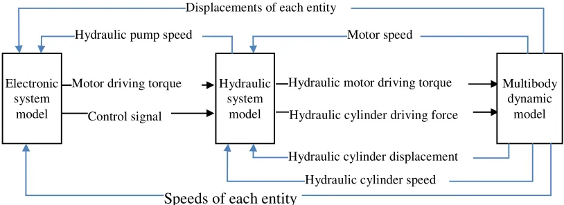
[image:1.612.102.509.538.686.2]All the states of the mechanical, electronic and hydraulic system are dynamically changed during the operation. Because of the interaction between the parameters of the mechanical, electronic and hydraulic system, the changes of these state variables have the characteristics of real time, continuous and coupling changes. The coupling relationship between the parameters of the mechanical, electronic and hydraulic system is shown in Figure 1.
Figure 1. Parameter coupling relationship of the mechanical, electronic and hydraulic system. Displacements of each entity
Speeds of each entity
Multibody dynamic
model Electronic
system model
Hydraulic system
model Hydraulic pump speed
Motor driving torque Control signal
Hydraulic motor driving torque
Hydraulic cylinder speed Motor speed
A Collaborative Simulation Scheme for the Mechanical, Electronic and Hydraulic System
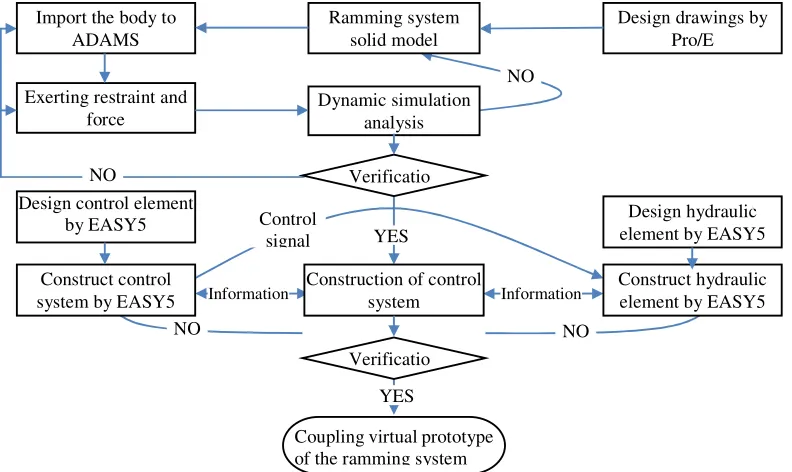
[image:2.612.110.506.183.419.2]There are many methods for collaborative simulation in multidisciplinary fields. A collaborative simulation strategy based on software interface is adopted in this paper. The software system uses MSC.ADAMS+EASY5. MSC.EASY5 as a unique multidisciplinary system and control system simulation software, mainly is used for the simulation of pneumatic, hydraulic, electrical, and control systems. As an authoritative multi body mechanism dynamics and kinematics simulation software, MSC.ADAMS completes the simulation of the motion part of the system executive mechanism. The collaborative simulation modeling process of the Ramming system is shown in Figure 2.
Figure 2. Collaborative simulation modelling process of the Ramming system.
Multibody Dynamic Model of the Ramming System
3D Solid Models
(a) Schematic diagram (b) model structure Figure 3. Reciprocating pushing projectile chain model.
The establishment of 3D solid model is a key step in the use of ADAMS to build virtual prototyping. It can be provided for dynamic analysis: (1) geometric and physical attributes information of each component; (2) true and accurate constraints and position information on the applied load. The reciprocating pushing projectile chain model in the transmission system is shown in Figure 3.
Information Import the body to
ADAMS
Exerting restraint and force
Design control element by EASY5 Construct control system by EASY5
Ramming system solid model
Dynamic simulation analysis Verificatio
Construction of control system
Coupling virtual prototype of the ramming system
Design drawings by Pro/E
Design hydraulic element by EASY5 Construct hydraulic element by EASY5 Control
signal
Information YES
NO
Verificatio YES
NO
[image:2.612.112.500.490.642.2]Definition of Topology Relation of Ramming System
The topology diagram of the ramming system is shown in Figure 4[2]. After adaptation to local simplification, the ramming system has 173 rigid bodies, 116 rotating hinges, 8 translational hinges, 23 fixed hinges, 5 Inline hinges, 1 Couple hinges and 441 contact hinges. There is a total of degree of freedoms:
173 6 116 5 8 5 23 6 5 2 1 1 441 0 269
DOF= × − × − × − × − × − × − × = (1)
B0—support of projectile mechanism, B1—front combined sprocket, B2—cartridge Storage I, B3—post combination sprocket, B4—rear projectile block, B5—projectile,
B6—front projectile block, B7—cartridge Storage I+1 Figure 4. Topology diagram of the ramming system.
Modeling of Control System
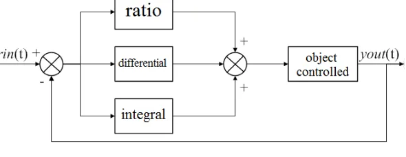
[image:3.612.161.456.460.574.2]The controller of the automatic ramming system adopts PID control, whose system principle diagram is shown in Figure 5. The system is composed of analog PID controller and controlled object.
Figure 5. PID control system principle diagram.
The PID controller is a linear controller, which makes up the control deviation݁ݎݎݎ(ݐ), according to the given value rin t( ) and the actual output valueyout t( ).
( ) ( ) ( )
error t =rin t −yout t (2)
The rule of PID control is
0 1
( ) 1
( ) ( ) t ( ) D
p
T derror t u t k error t error t dt
T dt
= + +
∫
(3)In the formula: kp is the ratio coefficient; T1is the integral time constant; TD is the differential
Modeling of the Mechanical, Electronic, Hydraulic and Control System
The schematic diagram of the mechanical, electronic, hydraulic and control system for ramming system is shown in figure 6[3].
[image:4.612.88.529.157.321.2]According to the schematic diagram of hydraulic system in Figure 6, the hydraulic subsystem model of the ramming system is built in MSC.EASY5, and it is coupled with the mechanical system model and control system model. The coupling simulation structure is shown in Figure 7.
Figure 6. Schematic diagram of hydraulic system. Figure 7. Coupling simulation structure.
x is the displacement of the chain, which establish the control equations in the MSC.Easy5; MAdams is the Sprocket driving torque, which is obtained by the function Varval (MEsay5) given the torque of the motor in the hydraulic system; θሶ is the sprocket rotation speed, used to build the pressure and flow equation in the MSC.Easy5; P, Q and P, Q for the import and export pressure
and flow of hydraulic motor.
Action Sequence Time Verification in the VV&A
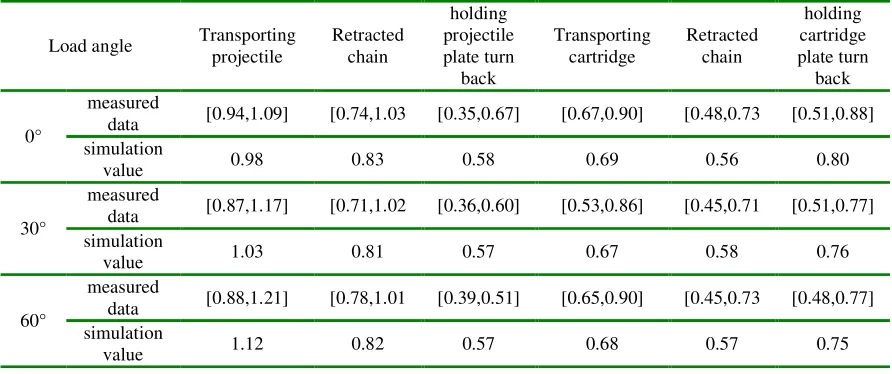
[image:4.612.83.529.556.743.2]In the VV&A verification of the virtual prototype of the ramming system, it relies mainly on the existing experimental data. The experiment records the action time by measuring the time of each control signal directly. These data are randomly selected from a large number of samples from a plant feeding cycle test. The statistical sample contains differences between individuals and different batches, which are very representative. Thus, this paper uses these experimental data to verify the effectiveness of the virtual prototype of the ramming system. Table 1 is the comparison of the measured data and the simulation value of the 20 artilleries feeding cycle test.
Table 1. Comparison of the measured data and the simulation value of action sequence time(unit:s).
Load angle Transporting projectile
Retracted chain
holding projectile plate turn
back
Transporting cartridge
Retracted chain
holding cartridge plate turn
back
0°
measured
data [0.94,1.09] [0.74,1.03 [0.35,0.67] [0.67,0.90] [0.48,0.73 [0.51,0.88] simulation
value 0.98 0.83 0.58 0.69 0.56 0.80
30°
measured
data [0.87,1.17] [0.71,1.02 [0.36,0.60] [0.53,0.86] [0.45,0.71 [0.51,0.77] simulation
value 1.03 0.81 0.57 0.67 0.58 0.76
60°
measured
data [0.88,1.21] [0.78,1.01 [0.39,0.51] [0.65,0.90] [0.45,0.73 [0.48,0.77] simulation
From the comparison of the tables, we can see that the simulation values fall within the interval of the time value of the experiment, indicating that the virtual prototype is credible. At the same time, it can be seen that the simulation value of the action time of the transporting cartridge process is somewhat smaller. It is the main reason that cartridge motion resistance decreases during modeling the simplified force of elastic claw of the holding cartridge plate and the cartridge.
Summary
The ramming system as the research object, aiming at the existing problems in the mechanical, electronic and hydraulic system coupling simulation, it is proposed that collaborative simulation scheme suitable for large complex system simulation. Then, the complete ramming system coupling virtual prototype is established, by solving the mechanical, electronic and hydraulic system coupling, variable topology of the ramming etc. The key sub model of virtual prototyping is verified by VV& A. The overall operation characteristics of the transmission system are verified by the experimental data. The results show that the proposed mechanical, electronic and hydraulic system coupling virtual prototype model has high precision and can meet the needs of engineering analysis.
References
[1] Xue Wen-xing, Qin Jun-qi, Jia Chang-zhi, Harmfulness analysis of trouble mode of feeding mechanism based on FMADM method, J. Fire Control & Command Control. 8 (2011) 152-159.
[2] Hong Jia-zheng, Computational dynamics of Multibody system, Beijing, 1999.