Rib Structure Optimization of Deployable Umbrella Reflector
Bo WANG
1, Zhou-yang LI
2, Huan-xiao LI
1, Zhuo XIE
2and Hui CHENG
2
1Xi′an Institute of Space Radio Technology, Xi’an 710100, China
2School of Mechanical Engineering, Northwestern Polytechnical University, Xi’an, 710072, China
Keywords: Deployable umbrella reflector, Structure optimization, Compound form method.
Abstract. In order to reduce the mass of satellite deployable umbrella reflector, a structure optimization model of rib was established by analyzing rib’s structure and forces on it. The minimum mass of rib is calculated by optimizing its structure parameters under given rigidity and loads. Optimized structure parameters were obtained by solving the model with Compound Form method. Comparing the original structure, 50.4% mass was successfully reduced after optimization. It was found that increasing the height of the rib's cross section and using variable section are two effective ways to make rib lighter.
Introduction
As a new structure type of satellite deployable antenna, umbrella deployable reflector has the distinct advantages of simple structure, high deployable reliability, adjustable surface precision and low manufacturing cost. It has become a focus in the field of deployable antenna in recent years and has been studied by space agencies of various countries [1,2]. Hasanzade V. et al. [3] proposed a compact umbrella antenna structure and analyzed its thermal deformation in space environment. Lopatin A.V. and Morozov E.V.[4] analyzed modal of large umbrella deployable antenna’s ribs by establishing free vibration equations. Lopatin A.V. et al. [5] built the model of reflective surface of umbrella-type antenna and calculated the root-mean-square error of surface. Li D.Y. et al. [6] analyzed the dynamic vibration characteristics of umbrella antenna by using finite element method when considering preload. Hu T.B. et al. [7] studied the movement reliability of rotation joint of umbrella antenna during deployment process. Wang P.P. et al. [8] studied the stability of umbrella antenna tension cable under the influence of temperature and gravity. Zhang Y.N. et al. [9] calculated the thermal deformation of radial support ribs by using finite element method. To sum up, existing research focuses on antenna deployment principle, overall structural design and cable network analysis, and there is the lack of structural optimization study for radial supporting rib.
The radial supporting rib is the most important component of umbrella reflector and it is constrained by rigidity and mass. The supporting rib produces bending deformation under the tension force of reflector and cable [10]. Therefore, in the design of supporting rib structure, it is necessary to ensure that the stiffness of supporting rib has enough safety reserve in order to reduce the mass of supporting rib.
Therefore, it is necessary to analyze stress state of supporting rib when antenna is working. The structural optimization design method is used to establish optimization model of rib structure. The rib is optimized to obtain optimal structural parameters that meet design requirements. It provides the basis for design of umbrella antenna structure.
Mechanical Characterizations
Figure 1. Structure of umbrella deployable reflector.
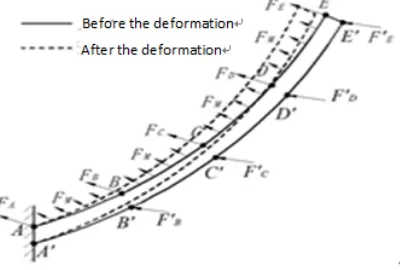
In order to ensure spatial shape and surface accuracy of reflector, it is necessary to apply a certain pre-tension on cables and metal reflection surface so that reflector’s surface forms required paraboloid with tension force applied on surface [11]. Ribs are pulled by tension cables and metal reflective surface on both sides [12]. And with the increase of deployment angle of the antenna, the tension will increase continuously. The tensile force of ribs reach the maximum value when ribs stretch to the maximum angle. At this time, at the junction with the front and rear tension cables, supporting ribs are affected by resultant forces FA,FB,,FEof two sides of the front tension cable’s tensions, and the rids also bear the resultant force FA,FB,,FEof two sides of the rear tension cable’s tensions. In addition, both sides of the rib is subjected to uniform pulling force from two sides of metal reflection surface. The forces of supporting rib is shown in Fig. 2. With the pull of cables and metal reflection surface, supporting ribs will have some bending deformation. The deformed supporting rib is shown by dotted line in Fig. 2.
Figure 2. Forces and deformation of rid.
Modeling and Optimization Analysis of Rid
Rib produces bending deformation under the concentrated force of tension cables and the distribution force of metal reflection surface. If the bending deformation is too large, tension cables and reflector surface will be relaxed, which leads to the decrease of surface precision and antenna can’t work properly [13]. Therefore, on the premise of meeting design requirement of rib deformation, rib needs to have as small as possible mass to meet the requirements of space application.
[image:2.612.195.395.368.503.2](a) Cross section of rib (b) Longitudinal section of rib Figure 3. The structure of rib.
According to the structure of rib shown in Fig. 3, on the premise of meeting requirement of deformation, the optimization model is established based on the minimum rib mass as optimization objective, and width at the root section, height of the root section, thickness of the longitudinal wall, thickness of the transverse wall and size ratio of the end section to the root section as design variables, as shown in Eq. 1.
1
2 4 2 5
3 3 1 5
min : ( ) ( )
s.t. ( ) ( ) [ ] 0
( ) 2 0
( ) 2 0
1, 2, , 5
i i i
f dv
g
g x x x
g x x x
a x b i
,
x x
x x
x
x
(1)
where f x( )is the mass of rib; v x( ) is the unit volume of rib; is the material density of rib;
1( )
g x is deformation constraint at the end section of rib; g x2( )is geometric constraint in high direction at the end section of rib; g x3( )is geometric constraint in wide direction at the end section
of rib; ( )x is deformation at the end section of rib; [ ] is allowable deformation at the end
section of rib;x1is width at the root section of rib; x2is height at the root section of rib;x3is thickness of longitudinal wall of rib; x4is thickness of transverse wall of rib; x5is size ratio of the
end section to the root section; ai,biare the lower and upper limit of the range of variable values. The value range of design variables, that isx( , , , , )x x x x x1 2 3 4 5 , is determined by actual structure and requirement of antenna.
The Solutions of Optimization Model of Rib
Compound Form method[14,15] are taken to solve the optimization model of rib. It is necessary to solve key problems such as the construction of initial compound form and the selection of compound form search method.
It is assumed that the number of compound form vertices n is equal to the number of design
variables plus one, this isn6.The initial point must be a feasible point satisfying constraint
condition, which is generated randomly. Based on design variablesxi
a bi, i
,i1,2, ,5 , thecomponents ofxsare calculated:
( ) , 1, 2, ,5 i i i i i
x a q b - a i (2)
where qi is a uniformly distributed random number within the interval (0,1).
One feasible vertex is given when initial compound form is produced, and other vertices are produced randomly, as shown in Eq. 2.
0.5( ) , 1, 2, ,
p o p o p m
x x x x (3)
where
m
is the number of the unfeasible vertices;xis geometric center of all feasible vertices.The reflection method is used to optimize the shape of compound form. First, objective function values of compound form vertices are calculated and compared, the worst pointxhis found.
( )h ( ),q 1, 2, ,
f x max f x q n (4) Then center pointxcof other vertices except pointxhis calculated, andxh xcis used as the
search direction to find reflection pointxr:
( )
r ct c h
x x x x (5)
where tis reflection coefficient, takingt 1.3.
By constantly adjusting the value of reflection coefficientt, reflection pointxris found and it
meets following conditions:
( ) 0 , 1, 2, 3
( ) ( ) j r r h g j f f x
x x (6)
The iteration ends when mean square deviation between all vertices and central point of compound form satisfies convergence condition shown in Eq. 7:
2 3 1
1
( )
( )
n q d qf
f
n
x
x
(7) wherexdis geometric center of compound form vertices n;3 is given error limit of objectivefunction value, taking 6 3 10
.
Calculation Result and Analysis of Optimization
The rid of antenna is made of carbon fiber, whose material density is =1.8 10 3 / 3
g mm
and Young modulus is E=9.0GPa. The original structure data of rib are shown in Table 1.
Table 1. The structural data of rib/mm.
Outer diameter Inner diameter Focus x1 x2 Height of the end Width of the end x3 x4
4000 200 1500 30 80 42 30 0.8 1.6
The mass of rib is 691.8gcalculated by data of Table 1. Considering the actual working condition of rib and ignoring the effect of gravity, the deformation at the end section of rib under given loads is 2.98mm. Therefore, the allowable deformation at the end section of rib is taken as 3mm in optimization model. Considering the constraints of rib strength, the condition that ribs can’t interfere with each other, the processing technology of carbon fiber and the actual assembly requirements, the range of parameters in optimization model is determined, as shown in Table 2.
Table 2. The range of parameters of rib/mm. Parameter
s x1 x2 x3 x4 x5 [ ]
Range [10,100] [10, 200] [0.5,5] [0.5,5] [0.1,1] 3.0
The result of calculation is shown in Table 3. It can be found that width at the root sectionx1,
thickness of the longitudinal wallx3and thickness of the transverse wallx4 are taken to lower limit
equal section or variable section in the process of optimization. So the conclusion is drawn that section width and wall thickness of rib contribute little to the ability of rib against bending deformation, and section height of rib is the key factor affecting ability of rib to resist bending deformation. Therefore, to enhance bending stiffness of rib, the first thing is to consider increasing section height of rib. At the same time, section width and wall thickness should be minimized to reduce structural mass under the premise of meeting structural and functional requirements.
Table 3. Optimization result of rib structure/mm.
Parameters x1 x2 x3 x4 x5
MassOrigin 80.00 30.00 0.8 1.6 -- 2.98 691.80g
Optimization with equal section 10.00 106.37 0.5 0.5 1.0 3.0 423.558g Compound Form method with variable section 10.00 154.39 0.5 0.5 0.1499 3.0 343.050g
From table 3, it can be seen that the mass of rib is obviously reduced after optimization. Compared with the original structure, mass of rib is reduced by 38.77% after optimizing structure with equal section, and mass of rib is reduced by 50.41% after optimizing structure with variable section. Therefore, compared with the form of equal section structure, variable section structure is more ideal, which should be given priority in structural design.
Conclusions
In this paper, the rib of deployable umbrella reflector is taken as object of study. Optimal design model of supporting rib is established based on the analysis of structure and force of rib. Optimal design results are obtained by using two optimization methods. It can be seen from analysis that the effect of weight reduction is more significant. At the same time, through the analysis of structural parameters optimization results, it is found that increasing height of section and adopting structure with variable cross section are main ways of rib’s optimization. The optimization method of this paper can also provide useful reference for optimization design of other similar structural parts.
Acknowledgement
This research was supported by the National Natural Science Foundation of China, (No. 51205322).
References
[1] Duan Baoyan. The State-of-the-Art and Development Trend of Large Space-Borne Deployable Antenna [J]. Electro-Mechanical Engineering, 2017, 33(01): 1-14.
[2] Tibert, G., Deployable Tensegrity Structures for Space Applications [M]. Stockholm, Sweden: Royal Institute of Technology, 2002: 9-33.
[3] Hasanzade V., Sedighy S.H., Shahravi M., Compact Deployable Umbrella Antenna Design with Optimum Communication Properties [J]. Journal of Spacecraft and Rockers, 2017, 54(3): 1-5. [4] Lopatin A.V., Morozov E.V., Modal Analysis of the Thin-Walled Composite Spoke of an Umbrella-Type Deployable Space Antenna [J]. Composite Structures, 2009, 88 (1): 46-55.
[5] Lopatin A.V., Rutkovskaya M., Gantovnik V., Accuracy Analysis of the Reflective Surface of the Umbrella-Type Antenna [J]. Journal of Spacecraft & Rockets, 2015, 45 (1): 149-151.
[6] Li Dongying, Zhang Hua, Liu Hanwu. Dynamics Modeling and Numerical Simulation of Radial Stiffening Rib-Membrane Umbrella Antenna Structure [J]. Journal of Dynamics and Control, 2017, 15(2): 131-135.
[8] Wang Pengpeng, Gao Bo, Song Jianming. Stability Analysis of Tensile Cable Network in Umbrella Antenna [J]. Chinese Journal of Applied Mechanics, 2015(3): 454-459.
[9] Zhang Yanna, Wan Renmin, Shen Junlong, et al. The Analysis of Main Rib Thermal Deformation Based on Finite Element Method for Radial Rib Antenna [J]. Electronics Quality, 2011, (11): 63-67.
[10] Zheng F., He J., Zhang P., Simulating Evaluation of New Space Deployable Antenna [J].Aircraft Engineering and Aerospace Technology, 2016, 88(6): 835-845.
[11] Tang Y.Q., Li T.J., Ma X.F., Hao L., Extended Nonlinear Force Density Method for Form-Finding of Cable-Membrane Structures [J]. Journal of Aerospace Engineering, 2016, 30(3): 04016101.
[12] Tang Y.Q., Li T.J., Equivalent-Force Density Method as a Shape-Finding Tool for Cable-Membrane Structures [J]. Engineering Structures, 2017, 151: 11-19.
[13] Fan Yesen, Li Tuanjie, Ma Xiaofei, Li Zhengjun. Form-Finding Method of Equal Tension Cable Networks for Space Mesh Antennas[J]. Journal of Xidian University, 2015, 42(1): 49-55. [14] Chen Lizhou., Yu Biqiang. Mechanical Optimization Design Method [M]. 4th edition. Beijing: Metallurgical Industry Press, 2014: 87-125.