CLI Command Reference
Layer 2 Switch
24 Port 10/100 Managed Switch
Plus 2 Combo Gigabit Copper/SFP Ports
Release 2
Table of Contents
List of Figures. . . 11
List of Tables . . . 13
About This Book . . . 15
Audience . . .
15
Document Organization . . .
15
Trademarks . . .
15
Copyright Statement . . .
15
D-Link DES-3226L Overview. . . 17
Scope . . .
17
Product Concept . . .
17
Command Structure . . . 19
Command Syntax . . .
19
Command Conventions . . .
19
Parameter Values . . .
20
Slot-Port Naming Convention . . .
21
CLI Line-Editing Conventions. . .
22
Using the “No” Form of a Command . . .
22
Using CLI Help . . .
23
Accessing the CLI . . .
23
Command-Line Interface Modes . . . 25
Mode-based Topology . . .
26
Mode-based Command Hierarchy . . .
26
Command Mode Description . . .
27
Flow of Operation. . .
28
Setup and Management Commands . . . 29
System Management Commands . . .
29
network parms . . .
29
network protocol . . .
29
network mgmt_vlan . . .
30
no network mgmt_vlan . . . 30
transport input telnet . . .
30
no transport input telnet . . . 30
telnetcon maxsessions . . .
30
no telnetcon maxsessions . . . 30
telnetcon timeout . . .
31
bridge aging-time. . .
31
no bridge aging-time . . . 31
network javamode . . .
31
no network javamode . . . 32
network mac-address . . .
32
network mac-type . . .
32
no network mac-type . . . 32
serial baudrate . . .
32
no serial baudrate . . . 33
serial timeout . . .
33
no serial timeout . . . 33
set prompt. . .
33
show forwardingdb agetime. . .
33
show network . . .
34
show telnetcon . . .
34
show serial . . .
35
System Configuration Commands. . .
35
addport. . .
35
cablestatus . . .
36
auto-negotiate . . .
36
no auto-negotiate . . . 36
auto-negotiate all . . .
36
no auto-negotiate all . . . 36
deleteport
(Interface Config) . . . 36deleteport
(Global Config) . . . 36monitor session . . .
37
no monitor session . . . 37
no monitor . . .
37
no monitor session 1 . . .
37
show monitor session 1 . . .
38
shutdown . . .
38
no shutdown . . . 38
shutdown all . . .
38
no shutdown all . . . 38
speed . . .
39
speed all . . .
39
storm-control broadcast. . .
39
no storm-control broadcast . . . 40
storm-control flowcontrol . . .
40
no storm-control flowcontrol . . . 40
show mac-address-table multicast . . .
40
show mac-address-table stats . . .
41
show monitor session . . .
41
show port . . .
41
show storm-control . . .
42
SNMP Community Commands . . .
42
snmp-server community. . .
43
no snmp-server community . . . 43
snmp-server community ipaddr . . .
43
no snmp-server community ipaddr . . . 43
snmp-server community ipmask . . .
43
no snmp-server community ipmask . . . 44
snmp-server community mode . . .
44
no snmp-server community mode . . . 44
snmp-server community ro . . .
44
snmp-server community rw . . .
44
snmp-server enable traps . . .
45
no snmp-server enable traps . . . 45
snmp-server enable traps linkmode. . .
45
no snmp-server enable traps linkmode . . . 45
snmp-server enable traps multiusers. . .
45
no snmp-server enable traps multiusers . . . 45
snmp-server enable traps stpmode . . .
46
no snmp-server enable traps stpmode . . . 46
snmptrap . . .
46
no snmptrap . . . 46
snmptrap snmpversion. . .
46
snmptrap ipaddr . . .
47
snmptrap mode . . .
47
no snmptrap mode . . . 47
snmp trap link-status . . .
47
no snmp trap link-status . . . 47
snmp trap link-status all . . .
47
no snmp trap link-status all . . . 48
show snmpcommunity . . .
48
show trapflags . . .
48
show snmptrap. . .
49
Switching Commands . . . 51
Virtual LAN (VLAN) Commands. . .
51
vlan . . .
51
no vlan . . . 51
vlan acceptframe . . .
51
no vlan acceptframe . . . 52
vlan name . . .
52
no vlan name . . . 52
vlan participation . . .
52
vlan participation all . . .
52
vlan port acceptframe all . . .
53
no vlan port acceptframe all . . . 53
vlan port pvid all . . .
53
no vlan port pvid all . . . 53
no vlan port tagging all . . . 54
vlan pvid. . .
54
no vlan pvid . . . 54
vlan tagging . . .
54
no vlan tagging . . . 54
show vlan . . .
55
show vlan brief. . .
55
show vlan port . . .
56
Protected Ports Commands . . .
56
switchport protected. . .
56
no switchport protected . . . 57
show switchport protected . . .
57
Link Aggregation/Port-Channel (802.3AD) Commands . . .
57
port-channel. . .
58
no port-channel . . . 58
clear port-channel . . .
58
port-channel staticcapability . . .
58
no port-channel staticcapability . . . 58
port lacpmode . . .
58
no port lacpmode . . . 59
port lacpmode all . . .
59
no port lacpmode all . . . 59
port-channel adminmode . . .
59
no port-channel adminmode . . . 59
port-channel linktrap . . .
59
no port-channel linktrap . . . 60
port-channel name . . .
60
show port-channel brief . . .
60
show port-channel . . .
60
IGMP Snooping Commands . . .
61
set igmp . . .
61
no set igmp . . . 62
set igmp interfacemode . . .
62
no set igmp interfacemode . . . 62
set igmp fast-leave . . .
62
no set igmp fast-leave . . . 62
set igmp groupmembership-interval . . .
63
no set igmp groupmembership-interval . . . 63
set igmp maxresponse . . .
63
no set igmp maxresponse . . . 63
set igmp mcrtexpiretime . . .
63
no set igmp mcrtexpiretime . . . 64
set igmp mrouter . . .
64
no set igmp mrouter . . . 64
set igmp mrouter interface . . .
64
no set igmp mrouter interface . . . 64
show igmpsnooping mrouter interface . . .
65
show igmpsnooping mrouter vlan . . .
66
show mac-address-table igmpsnooping . . .
66
Spanning Tree Protocol (STP) Commands . . .
66
spanning-tree . . .
66
no spanning-tree . . . 67
spanning-tree bpdumigrationcheck . . .
67
spanning-tree configuration name . . .
67
no spanning-tree configuration name . . . 67
spanning-tree configuration revision . . .
67
no spanning-tree configuration revision . . . 68
spanning-tree edgeport . . .
68
no spanning-tree edgeport . . . 68
spanning-tree forceversion . . .
68
no spanning-tree forceversion . . . 68
spanning-tree forward-time . . .
68
no spanning-tree forward-time . . . 69
spanning-tree hello-time . . .
69
no spanning-tree hello-time . . . 69
spanning-tree max-age . . .
69
no spanning-tree max-age . . . 69
spanning-tree max-hops . . .
69
no spanning-tree max-hops . . . 70
spanning-tree mst . . .
70
no spanning-tree mst . . . 70
spanning-tree mst instance . . .
71
no spanning-tree mst instance . . . 71
spanning-tree mst priority . . .
71
no spanning-tree mst priority . . . 71
spanning-tree mst vlan . . .
71
no spanning-tree mst vlan . . . 72
spanning-tree port mode . . .
72
no spanning-tree port mode . . . 72
spanning-tree port mode all . . .
72
no spanning-tree port mode all . . . 72
show spanning-tree . . .
73
show spanning-tree summary . . .
74
show spanning-tree interface . . .
74
show spanning-tree mst port detailed . . .
75
show spanning-tree mst port summary . . .
76
show spanning-tree mst summary . . .
77
show spanning-tree vlan . . .
77
GVRP Commands . . .
77
set gvrp adminmode. . .
77
no set gvrp adminmode . . . 78
set gvrp interfacemode . . .
78
show gvrp configuration . . .
78
Class of Service (CoS) Commands . . .
79
classofservice dot1p-mapping . . .
79
classofservice trust dot1p. . .
79
no classofservice trust . . . 79
traffic-shape . . .
79
no traffic-shape . . . 80
rate-limit . . .
80
no rate-limit . . . 80
show classofservice dot1p-mapping . . .
80
show classofservice trust . . .
81
show interfaces cos-queue . . .
81
Access and Security Commands . . . 83
User Account Commands . . .
83
users name . . .
83
no users name . . . 83
users passwd . . .
83
no users passwd . . . 84
users snmpv3 accessmode . . .
84
no users snmpv3 accessmode . . . 84
users snmpv3 authentication . . .
84
no users snmpv3 authentication . . . 85
users snmpv3 encryption . . .
85
no users snmpv3 encryption . . . 85
show loginsession. . .
85
show users . . .
86
disconnect . . .
86
Port-Based Network Access Control Commands . . .
86
authentication login . . .
86
no authentication login . . . 87
clear dot1x statistics . . .
87
clear radius statistics . . .
87
dot1x default-login . . .
87
dot1x initialize . . .
88
dot1x login . . .
88
dot1x max-req . . .
88
no dot1x max-req . . . 88
dot1x port-control . . .
88
no dot1x port-control . . . 89
dot1x port-control all . . .
89
no dot1x port-control All . . . 89
dot1x re-authenticate . . .
89
dot1x re-authentication . . .
89
no dot1x re-authentication . . . 89
dot1x system-auth-control . . .
90
dot1x timeout . . .
90
no dot1x timeout . . . 91
dot1x user . . .
91
no dot1x user . . . 91
users defaultlogin . . .
91
users login . . .
91
show authentication. . .
92
show authentication users . . .
92
show dot1x. . .
92
show dot1x users . . .
94
show users authentication . . .
94
RADIUS Commands . . .
95
radius accounting mode . . .
95
no radius accounting mode . . . 95
radius server host . . .
95
no radius server host . . . 96
radius server key . . .
96
radius server msgauth . . .
96
no radius server msgauth . . . 96
radius server primary . . .
96
radius server retransmit . . .
97
no radius server retransmit . . . 97
radius server timeout. . .
97
no radius server timeout . . . 97
show radius . . .
97
show radius accounting. . .
98
show radius statistics. . .
99
Secure Shell (SSH) Commands . . .
100
ip ssh . . .
100
no ip ssh . . . 100
ip ssh protocol . . .
100
sshcon maxsessions . . .
101
no sshcon maxsessions . . . 101
sshcon timeout . . .
101
no sshcon timeout . . . 101
show ip ssh. . .
101
Hypertext Transfer Protocol (HTTP) Commands. . .
102
ip http secure-port . . .
102
no ip http secure-port . . . 102
ip http secure-protocol. . .
102
ip http secure-server . . .
102
no ip http secure-server . . . 102
ip http server . . .
102
no ip http server . . . 103
show ip http . . .
103
System Maintenance Commands . . . 105
System Information and Statistics Commands . . .
105
show arp switch . . .
105
show eventlog. . .
105
show hardware . . .
106
show interface . . .
106
show interface ethernet . . .
107
show logging . . .
112
show mac-addr-table . . .
113
show running-config . . .
114
show sysinfo . . .
114
Logging Commands . . .
114
logging persistent. . .
114
no logging persistent . . . 115
logging host . . .
115
logging host remove . . .
115
logging syslog . . .
115
no logging syslog . . . 115
show logging . . .
115
show logging persistent . . .
116
show logging hosts. . .
116
show logging traplogs . . .
116
System Utility Commands . . .
117
traceroute . . .
117
clear config . . .
117
clear counters. . .
117
clear igmpsnooping . . .
117
clear pass . . .
118
enable passwd . . .
118
clear port-channel . . .
118
clear traplog. . .
118
clear vlan . . .
118
logout . . .
118
ping . . .
118
reload . . .
119
copy . . .
119
Configuration Scripting Commands . . .
120
script apply. . .
120
script delete . . .
121
script list. . .
121
script show . . .
121
script validate. . .
121
Glossary . . . 123
List of Figures
Figure 1. Mode-based CLI . . . 26
Figure 2. Syntax Error Message . . . 28
List of Tables
Table 1. Parameter Conventions . . . 20
Table 2. Parameter Descriptions . . . 20
Table 3. Type of Slots . . . 21
Table 4. Type of Ports . . . 21
Table 5. CLI Editing Conventions . . . 22
Table 6. CLI Command Modes . . . 25
About This Book
This document describes the command-line interface (CLI) commands that you use to view and configure settings for the D-Link DES-3226L switch.
Audience
This document is intended for system administrators who configure and operate systems using D-Link 3226L software. It provides an understanding of the configuration options of the D-Link DES-3226L software. This document assumes that the reader has a basic knowledge of Ethernet and networking concepts.
Document Organization
This document is organized into the following sections:
z “D-Link DES-3226L Overview” on page 17 introduces the D-Link DES-3226L software at a very high level.
z “Command Structure” on page 19 describes the command format and syntax.
z “Command-Line Interface Modes” on page 25 explains the CLI command modes.
z “Setup and Management Commands” on page 29 describes the commands you use to configure management access and basic port settings.
z “Switching Commands” on page 51 describes the commands you use to configure and view switch properties, such as VLANs and protected ports.
z “Access and Security Commands” on page 83 describes how to configure the device for secure access.
z “System Maintenance Commands” on page 105 describes the commands you use to view system information, view and configure system logs, troubleshoot connectivity, and restore various set-tings to their factory defaults.
Trademarks
Contents subject to change without prior notice.
D-Link is a registered trademark of D-Link Corporation/D-Link Systems, Inc. All other trademarks belong to their respective proprietors.
Copyright Statement
Copyright
©
2006 D-Link Corporation.No part of this publication may be reproduced in any form or by any means or used to make any derivative such as translation, transformation, or adaptation without permission from D-Link Corporation/D-Link Systems Inc., as stipulated by the United States Copyright Act of 1976.
D-Link DES-3226L Overview
The D-Link DES-3226Lsoftware has two purposes:
z Assist attached hardware in switching frames.
z Provide a complete device management portfolio to the network administrator.
Scope
The D-Link DES-3226L encompasses both hardware and software support. The software is partitioned to run in the following processors:
z CPU
This code runs the networking device management portfolio and controls the overall networking device hardware. It also assists in frame forwarding, as needed and specified.
z Networking device processor
This code does the majority of the packet switching, usually at wire speed.
Product Concept
Fast Ethernet and Gigabit Ethernet switching continues to evolve from high-end backbone applications to desktop switching applications. The price of the technology continues to decline, while performance and feature sets continue to improve. The D-Link DES-3226L provides a flexible solution to these ever-increasing needs.
The D-Link DES-3226L provides the network administrator with a set of comprehensive management functions for managing both the switch and the network. The network administrator has a choice of three management methods:
z Web-based
z VT100 interface
z Simple Network Management Protocol (SNMP)
Each of the D-Link DES-3226L management methods enables the network administrator to configure, manage, and control the D-Link DES-3226L locally or remotely by using in-band or out-of-band mechanisms. Management is standards-based, with configuration parameters and a private MIB providing control for functions not completely specified in the MIBs.
Command Structure
The command-line interface (CLI) is a text-based way to manage and monitor the system. You can access the CLI by using a direct serial connection or by using a remote logical connection with telnet or SSH.
This chapter describes the CLI syntax, conventions, and help. It contains the following sections:
z “Command Syntax” on page 19
z “Command Conventions” on page 19
z “Using the “No” Form of a Command” on page 22
z “Using CLI Help” on page 23
z “Accessing the CLI” on page 23
Command Syntax
A command is one or more words that might be followed by one or more parameters. Parameters can be required or optional values.
Some commands, such as show network or clear vlan, do not require parameters. Other commands, such as network parms, require that you supply a value after the command. You must type the parameter values in a specific order, and optional parameters follow required parameters. The following example describes the network parms command syntax:
Format
network parms <ipaddr> <netmask> [<gateway>]z network parms is the command name.
z <ipaddr> and <netmask> are parameters and represent required values that you must enter after you type the command keywords.
z [<gateway>] is an optional parameter, so you are not required to enter a value in place of the parameter.
The CLI Command Reference lists each command by the command name and provides a brief description of the command. Each command reference also contains the following information:
z Format shows the command keywords and the required and optional parameters.
z Mode identifies the command mode you must be in to access the command.
z Default shows the default value, if any, of a configurable setting on the device.
The show commands also contain a description of the information that the command shows.
Command Conventions
In this document, the command name is in bold font. Parameters are in italic font. You must replace the parameter name with an appropriate value, which might be a name or number. Parameters are order dependent.
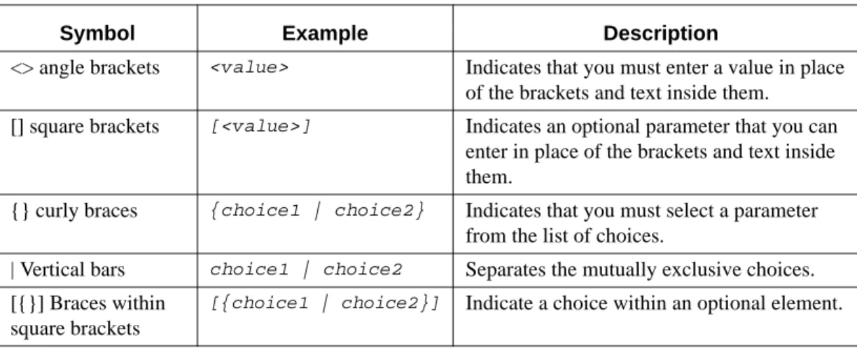
The parameters for a command might include mandatory values, optional values, or keyword choices. Table 1 describes the conventions this document uses to distinguish between value types.
Parameter Values
To use spaces as part of a name parameter, enclose the name value in double quotes. For example, the expression “System Name with Spaces” forces the system to accept the spaces. Empty strings (““) are not valid user defined strings.
The value 'Err' designates that the requested value was not internally accessible. This should never happen and indicates that there is a case in the software that is not handled correctly. The value of '---' designates that the value is unknown.
The following table describes common parameter values and value formatting.
Table 1. Parameter Conventions
Symbol Example Description
<> angle brackets <value> Indicates that you must enter a value in place of the brackets and text inside them.
[] square brackets [<value>] Indicates an optional parameter that you can enter in place of the brackets and text inside them.
{} curly braces {choice1 | choice2} Indicates that you must select a parameter from the list of choices.
| Vertical bars choice1 | choice2 Separates the mutually exclusive choices. [{}] Braces within
square brackets
[{choice1 | choice2}] Indicate a choice within an optional element.
Table 2. Parameter Descriptions
Parameter Description
ipaddr This parameter is a valid IP address. You can enter the IP address in the follow-ing formats:
a (32 bits) a.b (8.24 bits) a.b.c (8.8.16 bits) a.b.c.d
(8.8.8.8)
In addition to these formats, decimal, hexidecimal and octal formats are sup-ported through the following input formats (where n is any valid hexidecimal, octal or decimal number):
0xn (CLI assumes hexidecimal format)
0n (CLI assumes octal format with leading zeros) n (CLI assumes decimal format)
macaddr The MAC address format is six hexadecimal numbers separated by colons, for example 00:06:29:32:81:40.
interface Valid slot and port number separated by forward slashes. For example, 0/1 rep-resents slot number 0 and port number 1.
Slot-Port Naming Convention
D-Link DES-3226L software references physical entities such as cards and ports by using a Slot-Port (SP) naming convention. The D-Link DES-3226L software also uses this convention to identify certain logical entities such as Link Aggregation (LAG) or Port-Channel interfaces.
The slot number has two uses. In the case of physical ports, it identifies the card containing the ports. In the case of logical and CPU ports it also identifies the type of interface or port.
The port identifies the specific physical port or logical interface being managed on a given slot. Logical Interface Logical slot and port number. This is applicable in the case of a port-channel
(LAG). The operator can use the logical slot/port to configure the port-channel. Character strings Use double quotation marks to identify character strings, for example, “System
Name with Spaces”. An empty string (“”) is not valid.
Table 3. Type of Slots
Slot Type Description
Physical slot numbers Physical slot numbers begin with zero, and are allocated up to the maximum number of physical slots
Logical slot numbers Logical slots immediately follow physical slots and identify port-channel (LAG) interfaces.
CPU slot numbers The CPU slots immediately follow the logical slots.
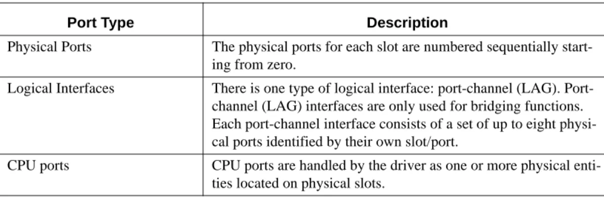
Table 4. Type of Ports
Port Type Description
Physical Ports The physical ports for each slot are numbered sequentially start-ing from zero.
Logical Interfaces There is one type of logical interface: port-channel (LAG). Port-channel (LAG) interfaces are only used for bridging functions. Each port-channel interface consists of a set of up to eight physi-cal ports identified by their own slot/port.
CPU ports CPU ports are handled by the driver as one or more physical enti-ties located on physical slots.
Table 2. Parameter Descriptions
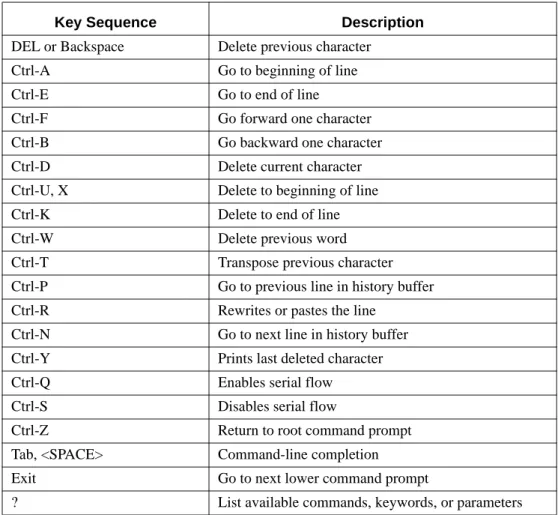
CLI Line-Editing Conventions
Table 5 describes the key combinations you can use to edit commands or increase the speed of command entry. You can access this list from the CLI by entering help from the User or Privileged EXEC modes.
Using the “No” Form of a Command
The no keyword is a specific form of an existing command and does not represent a new or distinct command. Almost every configuration command has a no form. In general, use the no form to reverse the action of a command or reset a value back to the default. For example, the no shutdown configuration command reverses the shutdown of an interface. Use the command without the keyword no to re-enable a disabled feature or to enable a feature that is disabled by default.
Only the configuration commands are available in the no form.
Table 5. CLI Editing Conventions
Key Sequence Description
DEL or Backspace Delete previous character Ctrl-A Go to beginning of line Ctrl-E Go to end of line
Ctrl-F Go forward one character Ctrl-B Go backward one character Ctrl-D Delete current character Ctrl-U, X Delete to beginning of line Ctrl-K Delete to end of line Ctrl-W Delete previous word Ctrl-T Transpose previous character Ctrl-P Go to previous line in history buffer Ctrl-R Rewrites or pastes the line
Ctrl-N Go to next line in history buffer Ctrl-Y Prints last deleted character Ctrl-Q Enables serial flow Ctrl-S Disables serial flow
Ctrl-Z Return to root command prompt Tab, <SPACE> Command-line completion Exit Go to next lower command prompt
Using CLI Help
Enter a question mark (?) at the command prompt to display the commands available in the current mode.
(switch) >?
enable Enter into user privilege mode.
help Display help for various special keys.
logout Exit this session. Any unsaved changes are lost. ping Send ICMP echo packets to a specified IP address. show Display switch options and settings.
Enter a question mark (?) after each word you enter to display available command keywords or parameters.
(switch) #network ?
javamode Enable/Disable.
parms Configure Network Parameters of the router. protocol Select DHCP, BootP, or None as the network config protocol.
mgmt_vlan Configure the Management VLAN ID of the switch.
If the help output shows a parameter in angle brackets, you must replace the parameter with a value.
(switch) #network parms ?
<ipaddr> Enter the IP Address.
If there are no additional command keywords or parameters, or if additional parameters are optional, the following message appears in the output:
<cr> Press Enter to execute the command
You can also enter a question mark (?) after typing one or more characters of a word to list the available command or parameters that begin with the letters, as shown in the following example:
(switch)# show m?
mac-addr-table mac-address-table monitor
Accessing the CLI
You can access the CLI by using a direct console connection or by using a telnet or SSH connection from a remote management host.
For the initial connection, you must use a direct connection to the console port. You cannot access the system remotely until the system has an IP address, subnet mask, and default gateway. You can set the network configuration information manually, or you can configure the system to accept these settings from a BOOTP or DHCP server on your network. For more information, see “System Management Commands” on page 29.
Command-Line Interface Modes
The CLI groups all the commands into modes according to the nature of the commands. This section describes the CLI command modes for the D-Link DES-3226L switch. Each of the command modes supports specific D-Link DES-3226L software commands.
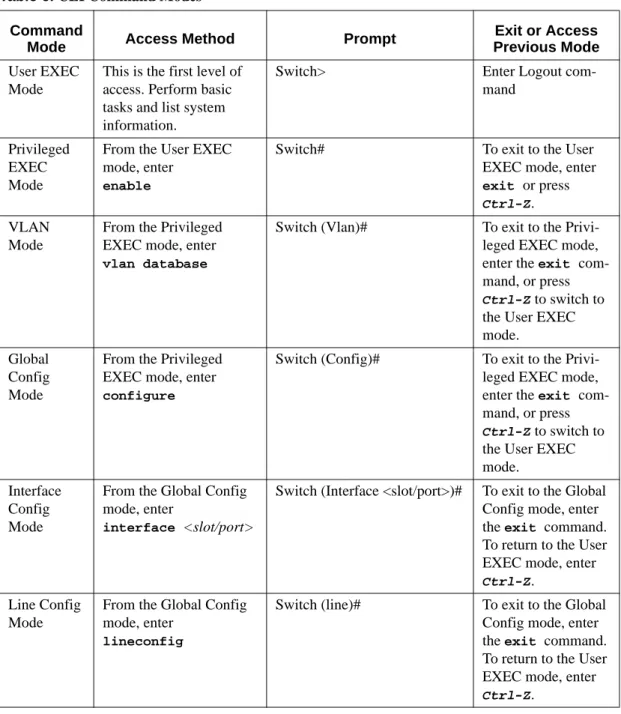
Table 6 lists the command modes and the prompts visible in that mode. It also explains how to enter or exit each mode.
Table 6. CLI Command Modes
Command
Mode Access Method Prompt
Exit or Access Previous Mode
User EXEC Mode
This is the first level of access. Perform basic tasks and list system information.
Switch> Enter Logout com-mand
Privileged EXEC Mode
From the User EXEC mode, enter
enable
Switch# To exit to the User EXEC mode, enter exit or press
Ctrl-Z. VLAN
Mode
From the Privileged EXEC mode, enter vlan database
Switch (Vlan)# To exit to the Privi-leged EXEC mode, enter the exit com-mand, or press
Ctrl-Z to switch to the User EXEC mode.
Global Config Mode
From the Privileged EXEC mode, enter configure
Switch (Config)# To exit to the Privi-leged EXEC mode, enter the exit com-mand, or press
Ctrl-Z to switch to the User EXEC mode.
Interface Config Mode
From the Global Config mode, enter
interface <slot/port>
Switch (Interface <slot/port>)# To exit to the Global Config mode, enter the exit command. To return to the User EXEC mode, enter
Ctrl-Z. Line Config
Mode
From the Global Config mode, enter
lineconfig
Switch (line)# To exit to the Global Config mode, enter the exit command. To return to the User EXEC mode, enter
Mode-based Topology
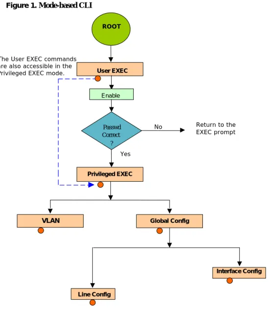
The CLI tree is built on a mode concept where the commands are available according to the interface. Some of the modes are depicted in Figure 1.
Figure 1. Mode-based CLI
Access to all commands in the Privileged EXEC mode and below are restricted through a password.
Mode-based Command Hierarchy
The commands in one mode are not available until you switch to that particular mode, with the exception of the User EXEC mode commands. You can execute the User EXEC mode commands in the Privileged EXEC mode.
The commands available to you depend upon the mode. To display a list of the available commands and descriptions of the commands, enter a question mark (?) at the CLI prompt.
Correc
t
User EXEC ROOT Enable Yes No Global Config VLAN Privileged EXEC Interface Config Line Config Passwd Correct ? The User EXEC commandsare also accessible in the Privileged EXEC mode.
Return to the EXEC prompt
Command Mode Description
This section describes the CLI command modes.
User EXEC Mode
When you log into the CLI, the User EXEC mode is the initial mode. The User EXEC mode contains a limited set of commands. The command prompt shown at this level is:
Command Prompt: Switch>
Privileged EXEC Mode
To have access to the full suite of commands, you must enter the Privileged EXEC mode. The Privileged EXEC mode requires password authentication. From Privileged EXEC mode, you can issue any EXEC command, enter the VLAN mode, or enter the Global Configuration mode. The command prompt shown at this level is:
Command Prompt: Switch#
VLAN Mode
This mode groups all the VLAN commands. The command prompt shown at this level is: Command Prompt: Switch(Vlan)#
Global Config Mode
This mode groups general setup commands and permits you to make modifications to the run-ning configuration. From the Global Configuration mode, you can enter the System Configura-tion mode, the Physical Port ConfiguraConfigura-tion mode, the Interface ConfiguraConfigura-tion mode, or the Protocol Specific modes specified below. The command prompt at this level is:
Command Prompt: Switch(Config)#
From the Global Config mode, you can enter the following configuration modes:
Interface Config Mode
Use the Interface commands to enable or modify the operation of an interface.
In this mode, a physical port is set up for a specific logical connection operation. The com-mand prompt at this level is:
Command Prompt: Switch(Interface <slot/port>)#
The resulting prompt for the interface configuration command entered in the Global Configu-ration mode is shown below:
Switch(Config)# interface 2/1 Switch(Interface 2/1)#
Line Config Mode
Use the Line Config mode to configure the console interface. You can configure the interface from the console connection or the virtual terminal used with Telnet. The command prompt at this level is:
Flow of Operation
This section describes the flow of operation for the CLI.
1. Log into the CLI session and enter the User EXEC mode. In the User EXEC mode the $(exec)> prompt displays on the screen.
You initiate the parsing process when you type a command and press <ENTER>. If you enter an incorrect or unavailable command, the output message indicates where the offending entry begins. For instance, if you enter show arpp brief (notice the extra p) instead of show arp brief, the output message is $(exec)> show arpp^ brief. $%Invalid input detected at '^' marker. The message shows you where the invalid input is detected. Figure 2 shows the layout of the output.
Figure 2. Syntax Error Message
After you enter the required parameters, any additional parameters you enter are treated as optional parameters. If any of the parameters are not recognized, a syntax error message is displayed.
2. After the command is successfully parsed and validated, the control of execution goes to the corre-sponding CLI callback function.
3. For required parameters, the command tree extends until the required parameters make the leaf of the branch. The callback function is only invoked when all the required parameters are provided. For optional parameters, the command tree extends until the required parameters and the optional parameters make the leaf of the branch. However, the callback function is associated with the node where the required parameters are fetched. The call back function then takes care of the optional parameters.
4. Once the control has reached the callback function, the callback function has complete information about the parameters you enter.
(exec) #show arpp brief
^
Setup and Management Commands
This section describes the commands you use to configure management access and basic port settings on the D-Link DES-3226L switch. This section contains the following subsections:
z “System Management Commands” on page 29
z “System Configuration Commands” on page 35
z “SNMP Community Commands” on page 42
The commands in this section are in one of three functional groups:
z Show commands display switch settings, statistics, and other information.
z Configuration commands configure features and options of the switch. For every configuration command, there is a show command that displays the configuration setting.
z Copy commands transfer or save configuration and informational files to and from the switch.
System Management Commands
You can use telnet to manage the D-Link DES-3226L switch from a remote management system. To manage the device locally, you can use a direct serial-cable connection. This section describes commands you use to manage remote and direct connections to the device. To manage the device by using SNMP, see “SNMP Community Commands” on page 42. To manage the device by using SSH, see “Secure Shell (SSH) Commands” on page 100.
To manage the device by using telnet, the switch must have an IP address, subnet mask, and default gateway. You can use network parms to configure the IP address, subnet mask, and default gateway, or you can use network protocol to configure the switch to request the information from a BOOTP or DHCP server on your network.
network parms
This command sets the IP Address, subnet mask and gateway of the device. The IP address and the gateway must be on the same subnet.
Format
network parms <ipaddr> <netmask> [<gateway>]Mode
Privileged EXECnetwork protocol
This command specifies the network configuration protocol to be used. If you modify this value, the change is effective immediately. The bootp parameter indicates that the switch periodically sends requests to a Bootstrap Protocol (BootP) server until a response is received. The dhcp parameter configures the switch to send periodic requests to a DHCP server until a response is received. The parameter none indicates that the switch should be manually configured with IP information.
Default
none
Format
network protocol {none | bootp | dhcp}network mgmt_vlan
This command configures the Management VLAN ID.
Default
1
Format
network mgmt_vlan <1-4069>Mode
Privileged EXECno network mgmt_vlan
This command sets the Management VLAN ID to the default.
Format
no network mgmt_vlan <1-4069>Mode
Privileged EXECtransport input telnet
This command regulates new telnet sessions. If sessions are enabled, new telnet sessions can be established until there are no more sessions available. If sessions are disabled, no new telnet sessions are established. An established session remains active until the session is ended or an abnormal network error ends the session.
Default
enabled
Format
transport input telnetMode
Line Configno transport input telnet
This command disables telnet sessions. If sessions are disabled, no new telnet sessions are established.
Format
no transport input telnetMode
Line Configtelnetcon maxsessions
This command specifies the maximum number of telnet connection sessions that can be established. A value of 0 indicates that no telnet connection can be established. The range is 0 to 5.
Default
5
Format
telnetcon maxsessions <0-5>Mode
Privileged EXECno telnetcon maxsessions
This command sets the maximum number of telnet connection sessions that can be established to the default value.
Format
no telnetcon maxsessionstelnetcon timeout
This command sets the telnet connection session timeout value, in minutes. A session is active as long as the session has not been idle for the value set. The time is a decimal value from 1 to 160.
Note: Changing the timeout value for active sessions does not become effective until the session is reaccessed. Also, any keystroke activates the new timeout duration.
Default
5
Format
telnetcon timeout <1-160>Mode
Privileged EXECno telnetcon timeout
This command sets the telnet connection session timeout value to the default.
Note: Changing the timeout value for active sessions does not become effective until the session is reaccessed. Also, any keystroke activates the new timeout duration.
Format
no telnetcon timeoutMode
Privileged EXECbridge aging-time
This command configures the forwarding database address aging timeout in seconds. In an IVL system, the [fdbid | all] parameter is required. The <seconds> parameter must be within the range of 10 to 1,000,000 seconds. Fdbid (Forwarding database ID) indicates which forwarding database's aging timeout is being configured. The All option is used to configure all forwarding database's agetime.
Default
300
Format
bridge aging-time <10-1,000,000> [fdbid | all]Mode
Global Configno bridge aging-time
This command sets the forwarding database address aging timeout to 300 seconds. In an IVL system, the [fdbid | all] parameter is required. Fdbid (Forwarding database ID) indicates which forwarding database's aging timeout is being configured. All is used to configure all forwarding database's agetime.
Format
no bridge aging-time [fdbid | all]Mode
Global Confignetwork javamode
This command specifies whether or not the switch should allow access to the Java applet in the header frame of the Web interface. When access is enabled, the Java applet can be viewed from the Web interface. When access is disabled, the user cannot view the Java applet.
Default
enabled
Format
network javamodeno network javamode
This command disallows access to the Java applet in the header frame of the Web interface. When access is disabled, the user cannot view the Java applet.
Format
no network javamodeMode
Privileged EXECnetwork mac-address
This command sets locally administered MAC addresses. The following rules apply:
z Bit 6 of byte 0 (called the U/L bit) indicates whether the address is universally administered (b'0') or locally administered (b'1').
z Bit 7 of byte 0 (called the I/G bit) indicates whether the destination address is an individual address (b'0') or a group address (b'1').
z The second character, of the twelve character macaddr, must be 2, 6, A or E. A locally administered address must have bit 6 On (b'1') and bit 7 Off (b'0').
Format.
network mac-address <macaddr>Mode.
Privileged EXECnetwork mac-type
This command specifies whether the burned in MAC address or the locally-administered MAC address is used.
Default
burnedin
Format
network mac-type {local | burnedin}Mode
Privileged EXECno network mac-type
This command resets the value of MAC address to its default.
Format
no network mac-typeMode
Privileged EXECserial baudrate
This command specifies the communication rate of the terminal interface. The supported rates are 1200, 2400, 4800, 9600, 19200, 38400, 57600, 115200.
Default
9600
Format
serial baudrate {1200 | 2400 | 4800 | 9600 | 19200 | 38400 |57600 | 115200}
no serial baudrate
This command sets the communication rate of the terminal interface.
Format
no serial baudrateMode
Line Configserial timeout
This command specifies the maximum connect time (in minutes) without console activity. A value of 0 indicates that a console can be connected indefinitely. The time range is 0 to 160.
Default
5
Format
serial timeout <0-160>Mode
Line Configno serial timeout
This command sets the maximum connect time (in minutes) without console activity.
Format
no serial timeoutMode
Line Configset prompt
This command changes the name of the prompt. The length of name may be up to 64 alphanumeric characters.
Format
set prompt <prompt_string>Mode
Privileged EXECshow forwardingdb agetime
This command displays the timeout for address aging. In an IVL system, the [fdbid | all] parameter is required.
Default
allFormat
show forwardingdb agetime [fdbid | all]Mode
Privileged EXECForwarding DB ID
Fdbid (Forwarding database ID) indicates the forwarding database
whose aging timeout is to be shown. The all option is used to display the
aging timeouts associated with all forwarding databases. This field displays
the forwarding database ID in an IVL system.
Agetime
In an IVL system, this parameter displays the address aging timeout for the
associated forwarding database.
show network
This command displays configuration settings associated with the switch's network interface. The network interface is the logical interface used for in-band connectivity with the switch via any of the switch's front panel ports. The configuration parameters associated with the switch's network interface do not affect the configuration of the front panel ports through which traffic is switched or routed.
Format
show networkModes
Privileged EXECUser EXEC
IP Address
The IP address of the interface. The factory default value is 0.0.0.0
Subnet Mask
The IP subnet mask for this interface. The factory default value is 0.0.0.0
Default Gateway
The default gateway for this IP interface. The factory default value is
0.0.0.0
Burned In MAC Address
The burned in MAC address used for in-band connectivity.
Locally Administered MAC Address
If desired, a locally administered MAC address
can be configured for in-band connectivity. To take effect, 'MAC Address
Type' must be set to 'Locally Administered'. Enter the address as twelve
hexa-decimal digits (6 bytes) with a colon between each byte. Bit 1 of byte 0 must
be set to a 1 and bit 0 to a 0, i.e. byte 0 should have the following mask 'xxxx
xx10'. The MAC address used by this bridge when it must be referred to in a
unique fashion. It is recommended that this be the numerically smallest MAC
address of all ports that belong to this bridge. However it is only required to
be unique. When concatenated with dot1dStpPriority a unique
BridgeIdenti-fier is formed which is used in the Spanning Tree Protocol.
MAC Address Type
Specifies which MAC address should be used for in-band
connectiv-ity. The choices are the burned in or the Locally Administered address. The
factory default is to use the burned in MAC address.
Network Configuration Protocol Current
Indicates which network protocol is being
used. The options are bootp, dhcp, and none.
Java Mode
Specifies if the switch should allow access to the Java applet in the header
frame. Enabled means the applet can be viewed. The factory default is
dis-abled.
Web Mode
Specifies if the switch should allow access to the Web Interface.
show telnetcon
This command displays telnet settings.
Format
show telnetconModes
Privileged EXECUser EXEC
Remote Connection Login Timeout (minutes)
This object indicates the number of
minutes a remote connection session is allowed to remain inactive before
being logged off. May be specified as a number from 1 to 160. The factory
default is 5.
Maximum Number of Remote Connection Sessions
This object indicates the number
of simultaneous remote connection sessions allowed. The factory default is 5.
Allow New Telnet Sessions
Indicates that new telnet sessions will not be allowed when set
to no. The factory default value is yes.
show serial
This command displays serial communication settings for the switch.
Format
show serialModes
Privileged EXECUser EXEC
Serial Port Login Timeout (minutes)
Specifies the time, in minutes, of inactivity on a
Serial port connection, after which the Switch will close the connection. Any
numeric value between 0 and 160 is allowed, the factory default is 5. A value
of 0 disables the timeout.
Baud Rate (bps)
The default baud rate at which the serial port will try to connect. The
available values are 1200, 2400, 4800, 9600, 19200, 38400,57600, and
115200 baud. The factory Default is 9600 baud.
Character Size (bits)
The number of bits in a character. The number of bits is always 8.
Flow Control
Whether Hardware Flow-Control is enabled or disabled. Hardware Flow
Control is always disabled.
Stop Bits
The number of Stop bits per character. The number of Stop bits is always 1.
Parity Type
The Parity Method used on the Serial Port. The Parity Method is always
None.
System Configuration Commands
This section describes the commands you use to view and configure port settings.
addport
This command adds one port to the port-channel (LAG). The first interface is a logical slot and port number of a configured port-channel.
Note: Before adding a port to a port-channel, set the physical mode of the port. For more information, see “speed” on page 39.
Format
addport <logical slot/port>cablestatus
This command tests the status of the cable attached to an interface.
Format
cablestatus <slot/port>Mode
Privileged EXECauto-negotiate
This command enables automatic negotiation on a port. The default value is enable.
Format
auto-negotiateMode
Interface Configno auto-negotiate
This command disables automatic negotiation on a port.
Note: Automatic sensing is disabled when automatic negotiation is disabled.
Format
no auto-negotiateMode
Interface Configauto-negotiate all
This command enables automatic negotiation on all ports. The default value is enable.
Format
auto-negotiate allMode
Global Configno auto-negotiate all
This command disables automatic negotiation on all ports.
Format
no auto-negotiate allMode
Global Configdeleteport
(Interface Config)This command deletes the port from the port-channel (LAG). The interface is a logical slot and port number of a configured port-channel.
Format
deleteport <logical slot/port>Mode
Interface Configdeleteport
(Global Config)This command deletes all configured ports from the port-channel (LAG). The interface is a logical slot and port number of a configured port-channel.
Format
deleteport {<logical slot/port> | all}monitor session
This command configures a probe port and a monitored port for monitor session (port monitoring). The first <slot/port> is the source monitored port and the second <slot/port> is the destination probe port. The monitor session (port monitoring) mode becomes enabled only when both the probe and monitored ports are configured. If enabled, the probe port monitors all the traffic received and transmitted on the physical monitored port.
Format
monitor session <session-id> source interface <slot/port>desti-nation interface <slot/port>
Mode
Global Configno monitor session
This command removes the monitor session (port monitoring) designation from the source probe port, the destination monitored port and all VLANs. Once the port is removed from the VLAN, the user must manually add the port to any desired VLANs.
Note: This command sets the monitor session (port monitoring) mode to disable.
Format
no monitor session <session-id>Mode
Global Configno monitor
This command removes all the source ports and a destination port and restores the default value for mirroring session mode for all the configured sessions.
Note: This is a stand-alone “no” command. This command does not have a “normal” form.
Default
enabled
Format
no monitorMode
Global configno monitor session 1
This command removes all the source ports and a destination port of the mirroring session and restores the default value for mirroring session mode. The <session-id> parameter is an integer value used to identify the session. In the current version of the software, the <session-id> parameter is always 1.
Note: This is a stand-alone “no” command and does not have a “normal” form. This com-mand can be issued without regard for the session status (enabled or disabled).
Default
enabled
Format
no monitor session <session-id>show monitor session 1
This command displays the port monitoring information for a particular mirroring session.
Note: The <session-id> parameter is an integer value used to identify the session. In the cur-rent version of the software, the <session-id> parameter is always 1.
Format
show monitor session <session-id>Mode
Privileged EXECSession ID
It is an integer value used to identify the session.
Monitor Session Mode
It indicates whether the Port Mirroring feature is enabled or
dis-abled for the session identified with <session-id>. The possible values are
Enabled and Disabled.
Probe Port
It is the probe port (destination port) for the session identified with
<session-id>. If probe port is not set, this field is blank.
List of Source Ports
It is the list of ports, which are configured as mirrored ports (source
ports) for the session identified with <session-id>. If no source port is
config-ured for the session then this field is blank.
shutdown
This command disables a port.
Default
enabled
Format
shutdownMode
Interface Configno shutdown
This command enables a port.
Format
no shutdownMode
Interface Configshutdown all
This command disables all ports.
Default
enabled
Format
shutdown allMode
Global Configno shutdown all
This command enables all ports.
Format
no shutdown allspeed
This command sets the speed and duplex setting for the interface.
Format
speed {100 | 10} {half-duplex | full-duplex}Mode
Interface ConfigAcceptable values are:
100h
100BASE-T half duplex
100f
100BASE-T full duplex
10h
10BASE-T half duplex
10f
10BASE-T full duplex
speed all
This command sets the speed and duplex setting for all interfaces.
Format
speed all {<100 | 10> <half-duplex | full-duplex>}Mode
Global ConfigAcceptable values are:
100h
100BASE-T half-duplex
100f
100BASE-T full duplex
10h
10BASE-T half duplex
10f
10BASE-T full duplex
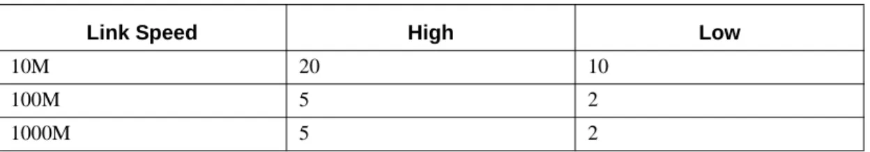
storm-control broadcast
This command enables broadcast storm recovery mode. If the mode is enabled, broadcast storm recovery with high and low thresholds is implemented.
The threshold implementation follows a percentage pattern. If the broadcast traffic on any Ethernet port exceeds the high threshold percentage (as represented in Table 7) of the link speed, the switch discards the broadcasts traffic until the broadcast traffic returns to the low threshold percentage or less. The full implementation is depicted in Table 7.
Format
storm-control broadcastMode
Global ConfigTable 7. Broadcast Storm Recovery Thresholds
Link Speed High Low
10M 20 10
100M 5 2
no storm-control broadcast
This command disables broadcast storm recovery mode.
The threshold implementation follows a percentage pattern. If the broadcast traffic on any Ethernet port exceeds the high threshold percentage (as represented in Table 7 on page 39) of the link speed, the switch discards the broadcasts traffic until the broadcast traffic returns to the low threshold percentage or less. The full implementation is depicted in Table 7.
Format
no storm-control broadcastMode
Global Configstorm-control flowcontrol
This command enables 802.3x flow control for the switch and only applies to full-duplex mode ports.
Note: 802.3x flow control works by pausing a port when the port becomes oversubscribed and dropping all traffic for small bursts of time during the congestion condition. This can lead to high-priority and/or network control traffic loss.
Default
disabled
Format
storm-control flowcontrolMode
Global Configno storm-control flowcontrol
This command disables 802.3x flow control for the switch.
Note: This command only applies to full-duplex mode ports.
Format
no storm-control flowcontrolMode
Global Configshow mac-address-table multicast
This command displays the Multicast Forwarding Database (MFDB) information. If the command is entered with no parameter, the entire table is displayed. This is the same as entering the optional all
parameter. You can display the table entry for one MAC Address by specifying the MAC address as an optional parameter.
Format
show mac-address-table multicast <macaddr | all>Mode
Privileged EXECMAC Address
A multicast MAC address for which the switch has forwarding and or
filter-ing information. The format is two-digit hexadecimal numbers separated by
colons, for example 01:23:45:67:89:AB. In an IVL system the MAC address
will be displayed as a MAC address and VLAN ID combination of 8 bytes.
Type
This displays the type of the entry. Static entries are those that are configured
by the end user. Dynamic entries are added to the table as a result of a learning
process or protocol.
Component
The component that is responsible for this entry in the Multicast Forwarding
Database. Possible values are IGMP Snooping, and Static Filtering.
Description
The text description of this multicast table entry.
Interfaces
The list of interfaces that are designated for forwarding (Fwd:) and filtering
(Flt:).
Forwarding Interfaces
The resultant forwarding list is derived from combining all the
component’s forwarding interfaces and removing the interfaces that are listed
as the static filtering interfaces.
show mac-address-table stats
This command displays the Multicast Forwarding Database (MFDB) statistics.
Format
show mac-address-table statsMode
Privileged EXECTotal Entries
Displays the total number of entries that can possibly be in the Multicast
For-warding Database table.
Most MFDB Entries Ever Used
Displays the largest number of entries that have been
present in the Multicast Forwarding Database table. This value is also known
as the MFDB high-water mark.
Current Entries
Displays the current number of entries in the MFDB.
show monitor session
This command displays the port monitoring information for the system.
Format
show monitor session <sessionid>Mode
Privileged EXECSession ID
The session identifying number.
Admin Mode
Indicates whether the Port Monitoring feature is enabled or disabled. The
possible values are enable and disable.
Probe Port
The interface configured as the probe port.
Mirrored Port
The interface configured as the mirrored port.
show port
This command displays port information.