Manual EN
ISOMETER® IRDH575
Insulation monitoring device for IT AC and DC systems
with integrated test generator and controller for
EDS46..., EDS47... and EDS49... systems
Bender GmbH & Co. KG
Londorfer Str. 65 • 35305 Gruenberg • Germany Postfach 1161 • 35301 Gruenberg • Germany Tel.: +49 6401 807-0
Fax: +49 6401 807-259 Email: [email protected] Web: http://www.bender.de
©
Bender GmbH & Co. KG All rights reserved.Table of Contents
1. How to use this documentation effectively ... 7
1.1 Use for the intended purpose ... 7
1.2 Safety information ... 7
1.3 Warranty and liability ... 8
1.4 Explanations of symbols and warnings ... 8
2. Function ... 9
2.1 General characteristics ... 9
2.2 Essential functions of the ISOMETER® ... 9
2.3 Essential functions of the Insulation fault location system (EDS) ... 9
2.4 Product description ... 10
2.5 Function ... 10
2.5.1 Current output for external measuring instrument ... 11
2.5.2 Real-time clock ... 11
2.5.3 Insulation fault location ... 11
2.5.4 Interconnected systems ... 12
2.5.5 Function input F1/F2 for connection or disconnection of IT systems being monitored ... 12
2.5.6 ISOnet function for central control of the insulation monitoring process when several IRDH575 are interconnected in IT systems ... 14
2.5.7 Self test ... 15
2.5.8 Relay K3: device fault alarm and EDS common message ... 17
2.5.9 Factory setting ... 17
3. Commissioning flow chart ... 19
3.1 Commissioning of the ISOMETER® function range (1) ... 19
3.2 Commissioning of the insulation fault location function (EDS) (1) ... 21
Table of Contents
5. Operation and setting ... 29
5.1 Operating features and displays IRDH575 ... 29
5.1.1 Display in case of active EDS and detected fault ... 30
5.1.2 Display in the menu mode ... 31
5.1.3 Function keys ... 31
5.2 Menu structure and menu mode ... 33
5.2.1 Diagram menu structure ... 34
5.3 HISTORY INFO menu ... 36
5.3.1 Diagram HISTORY INFO ... 37
5.4 ISO SETUP menu: Setting of the basic ISOMETER® functions ... 38
5.4.1 Response values Alarm 1 and Alarm 2 ... 38
5.4.2 Starting the EDS system via the response values ALARM 1 and ALARM 2 ... 38
5.4.3 Operating principle of the alarm relays ... 38
5.4.4 Memory setting (on/off) ... 40
5.4.5 Current output for external measuring instruments ... 41
5.5 ISO ADVANCED menu: Setting of the extended functions ... 42
5.5.1 External coupling device (AGH: no = factory setting) ... 42
5.5.2 Selecting the system leakage capacitance range ... 42
5.5.3 Changing the measuring principle from AMP to DC (Measure: AMP) 42 5.5.4 Setting the repetition time for automatic self tests (Autotest: 24h) ... 42
5.5.5 Setting the real-time clock (Clock) ... 42
5.5.6 Setting the date (Date) ... 42
5.5.7 Specifying the starting time of the automatic self test (Test) ... 42
5.5.8 Diagram ISO ADVANCED ... 43
5.6 EDS-SETUP menu: Settings for fault location ... 44
5.6.1 EDS auto / on / off / pos / 1cycle ... 44
5.6.2 Diagram EDS-SETUP ... 45
5.6.3 System DC / 1 AC / 3 AC ... 46
5.6.4 maxPuls 1 / 2.5 / 10 / 25 / 50 mA: ... 46
5.6.5 K3 alarm: ON ... 48
5.7 EDS460/490 menu ... 49
Table of Contents
5.7.3 Relay ... 51
5.7.4 EDS Test ... 52
5.7.5 EDS Reset ... 52
5.8 EDS 470 menu ... 54
5.8.1 EDS Monitor ... 54
5.8.2 EDS Test ... 54
5.8.3 EDS Reset ... 54
5.8.4 Details about the menu points Relay, Memory and n-peak ... 54
5.8.5 Diagram EDS 470 ... 55
5.8.6 Relay ... 56
5.8.7 Memory ... 56
5.8.8 CT Setup: ... 56
5.8.9 n-peak: ... 57
5.9 COM SETUP menu: Setting the BMS interface ... 58
5.9.1 Bus address (Addr: ) ... 58
5.9.2 ISO Monitor ... 58
5.9.3 ISOnet ... 59
5.9.4 Diagram COM SETUP ... 59
5.10 PASSWORD menu ... 60
5.10.1Activating and setting the password ... 60
5.10.2Diagram PASSWORT ... 60
5.11 Menu LANGUAGE ... 61
5.11.1Setting the national language ... 61
5.11.2Diagram Language ... 61
5.12 Menu SERVICE ... 62
5.13 Parameterization via Internet ... 62
6. Serial interfaces ... 63
6.1 RS485 interface with BMS protocol ... 63
6.2 Topology RS485 network ... 64
6.2.1 Correct arrangement ... 64
6.2.2 Wrong arrangement ... 64
6.2.3 Wiring ... 64
Table of Contents
6.3.1 BMS Master ... 65
6.3.2 BMS-Slave ... 66
6.3.3 BMS operation in the Standby mode ... 67
6.3.4 Combination with EDS46... devices ... 68
6.3.5 Commissioning of an RS485 network with BMS protocol ... 69
7. Technical data IRDH575 ... 71
7.1 Data in tabular form ... 71
7.2 Standards, approvals and certifications ... 74
7.3 Characteristic curves ... 75
7.3.1 Characteristic curves of the ISOMETER® ... 75
7.3.2 Characteristic curves of the insulation fault locators EDS46... /EDS49... ... 78
7.3.3 Characteristic curves for the insulation fault location system EDS470 . 80 7.4 Ordering details ... 88
7.4.1 Standard version ... 88
7.4.2 Protection against dust and moisture ... 88
7.4.3 Adaptor for rail mounting ... 89
7.4.4 Measuring instruments ... 89
1. How to use this documentation effectively
This operating manual is intended to address qualified experts in electrical engineering!
1.1 Use for the intended purpose
The ISOMETER® is exclusively intended for: monitoring the insulation resistance of IT systems and
localization of insulation faults in combination with insulation fault evaluators EDS4…
Any other use, or any use which goes beyond the foregoing, is deemed to be use other than for the intended purpose.
1.2 Safety information
General safety information
In addition to this operating manual, the documentation includes the supplementary sheet „Important safety instructions for Bender Products“.
Device-specific safety information
Only one insulation monitoring device may be used in each intercon-nected IT system.
When insulation or voltage test are to be carried out, the device shall be isolated from the system for the test period.
If the terminals L1, L2, L3 of the device are connected to a system under operation, the terminals and KE must not be disconnected from the protective conductor (PE).
How to use this documentation effectively
1.3 Warranty and liability
As a basic principle, the general conditions for the supply of products and services of the electrical and electronics (recommended by ZVEI (German Electrical and Electronic Manufacturers’ Association)) shall apply. As the latest, these shall be available to the operator when the contract is concluded.
1.4 Explanations of symbols and warnings
The following symbols are used in Bender documentation to draw attention to important information and to make it easier to find certain text passages. The following examples explain the meaning of the symbols:
The "Attention" symbol is used to draw attention to information warning employees of hazardous situations.
Information you should know for correct handling of the product is marked with the "Info" symbol.
2. Function
2.1 General characteristics
Four-line LC display Automatic device self-test
Memory with real-time clock to store all alarm messages with date and time stamp
RS485 interface (BMS protocol) for data exchange with other Bender devices (RS485 electrically isolated)
Remote setting of certain parameters via the Internet (option; FTC470XET additionally required)
Option "W":
Improved shock and vibration resistance for use in ships, on rolling stock and in seismic environment.
2.2 Essential functions of the ISOMETER®
ISOMETER® for IT AC systems with galvanically connected rectifiers and for IT DC systems (isolated power)
Automatic adaptation to the existing system leakage capacitances measuring principle (European Patent: EP 0 654 673 B1)
Two adjustable response values in the range 1 kΩ …10 MΩ (Alarm 1/Alarm 2) Connection monitoring
Internal disconnection of the ISOMETER from the IT system to be monitored (using a control signal; terminals F1/F2) , e.g. if several ISOMETERs® are intercon-nected.
Current output 0(4)…20mA (galvanically separated) in relation to the measured insulation value.
2.3 Essential functions of the Insulation fault location system (EDS)
Generation of the test current necessary for selective insulation fault location Indication of the insulation faults selectively localized by the EDS4… systems Parameterization of EDS4… systemsFunction
2.4 Product description
The IRDH575 ISOMETER® monitors the insulation resistance of IT systems. It is suitable for universal use in 3(N)AC, AC/DC and DC systems. AC systems may include extensive DC supplied loads, such as converters or thyristor-controlled DC drives. The device automatically adapts itself to the existing system leakage capacitance.
The IRDH575 ISOMETER® is fitted into an enclosure for panel mounting,
144 x 96 mm (WxH). For protection against dust and moisture, a panel seal (IP42) or a front-face transparent cover (IP65) are available as accessories, see Page 88.
The IRDH575 can be used in combination with a control and indicating device, PRC1470 version 2 or higher, for example, on the BMS (BMS = Bender Measuring Device Interface) bus.
2.5 Function
The IRDH575 ISOMETER® is connected between the unearthed system and the protective conductor (PE).
The response values and other function parameters are set via the function keys. The parameters are indicated on the LC display and are stored in a non-volatile memory (EEPROM) after the setting is completed.
A microprocessor-controlled pulsating AC measuring voltage is superimposed on the system ( measuring principle*). The measuring cycle consists of positive and negative pulses of the same amplitude. The period depends on the respective system leakage capacitances and the insulation resistance of the system to be monitored. An insulation fault between system and earth closes the measuring circuit. From the measured current value, the microprocessor calculates the insulation resistance which is indicated on the LC display or the external kΩ measuring instrument.
The measuring time is determined by the system leakage capacitances, the insulation resistance, and the system-related interference disturbances. System leakage
capacitances do not influence the measuring accuracy.
If the reading is below the selected response values ALARM1/ALARM2, the associated alarm relays respond and the alarm LEDs "ALARM1/2" light up and the measuring value is indicated on the LC display (in the event of DC insulation faults, the faulty supply line is indicated). The fault indication can be stored by bridging the terminals R1/R2
When an AC system includes galvanically connected DC circuits, the following shall be considered:
Insulation faults in DC circuits can only be monitored correctly when the rectifiers carry a continuous load of at least 5…10 mA.
Function
Pressing the external or internal RESET button, resets the fault message, provided that the insulation resistance is at least 25 % above the preset value.
R1/R2 bridged + Memory:on fault memory activated
R1/R2 bridged + Memory:off fault memory activated
R1/R2 not connected + Memory:on fault memory activated R1/R2 not connected + Memory:off fault memory deactivated *) measuring principle "adaptive measuring pulse", a measuring principle developed by Bender.
2.5.1 Current output for external measuring instrument
The current output of IRDH575 provides 0(4)…20 mA. The current output is electrically isolated from the device electronics and the RS485 interface. The ISO SETUP menu, on Page 41, allows to switch over between 0…20 mA and 4…20 mA.
2.5.2 Real-time clock
The real-time clock serves as a time base for the historical memory and self test function. At first the correct time and date must be set in the menu
"ISO ADVANCED". If time and date are not set, a "C" (clock) is flashing in the
standard display. In the event of a supply voltage failure, time and date will be stored for thirty days. If the 24 h self test is activated in the ISO ADVANCED menu,
a special time of day can be selected for the execution of the self test in the menu "TEST: 12:00". Then a self test will be started automatically once a day exactly at the preset time. If the 1 h test has been selected, the self test is automatically carried out every full hour.
2.5.3 Insulation fault location
Another function of the IRDH575 is selective insulation fault location. If the value of the insulation resistance falls below the set response values ALARM 1 and ALARM 2, a certain test current is generated by the IRDH575. The maximum value of the test current is determined by the maxPuls parameter, see page 46. In combination with an insulation fault evaluator EDS47…and the associated measuring current transformers connected to it, the insulation fault is selectively detected. The detected insulation fault is signalled to the IRDH575 via the RS485 interface (BMS protocol) and is then indicated by an alarm LED and indicated on the display. In the Master mode (Addr. 1), this alarm message is indicated by the alarm relay K3 as common alarm.
During the insulation fault location process the insulation monitoring function is deactivated. If the test current falls below the value the EDS4… is capable of measuring,
Function
the insulation fault location process will be stopped by IRDH575.
2.5.4 Interconnected systems
When using ISOMETER®s in IT systems care shall be taken that only one active ISOMETER® is connected in each interconnected system. If IT systems are intercon-nected via coupling switches, make sure that ISOMETERs not currently used are disconnected and deactivated via a control system. IT systems coupled via diodes or capacitances may also influence the insulation monitoring process. Hence, also in this case a central control of the different ISOMETER®s is required.
2.5.5 Function input F1/F2 for connection or disconnection of IT systems being monitored
The ISOMETER® can be disconnected from the IT system and set to STANDBY mode with the function input F1/F2. When the input F1/F2 is bridged, the terminals L1/L2 are iso-lated from the measuring circuit via internal coupling relays and terminal L3 remains connected to the measuring circuit via a resistor of 10 MΩ. The measuring function is stopped and the message „STANDBY“ appears on the display. When using software version 1.4 or higher, the latest measured insulation resistance is blanked and the value > 10 MΩ appears on the display. Furthermore, the alarm relays and alarm LEDs no longer provide alarm messages. Insulation faults already detected will be indicated by all EDS4…devices.
After opening the function input F1/F2, first of all the connection to the IT system will be restored and a completely new measuring cycle for insulation monitoring will be started. Using this function, selective disconnection of an IRDH575 in interconnected IT systems can be carried out via auxiliary contacts of the respective coupling switch. One coupling switch each in a line-type or ring-type arrangement can deactivate a sub-sequent IRDH575. This arrangement guarantees that only one ISOMETER® is active in each galvanically connected IT system.
Theoretically speaking, in a ring-type arrangement with all coupling switches closed, all ISOMETER®s would be deactivated. In order to prevent this, a BMS Master (IRDH575 Adr1) monitors the condition of the function input F1/F2 of all Slave ISOMETER®s. When all Slave ISOMETER®s are in the STANDBY mode, the insulation monitoring func-tion of the Master ISOMETER® remains active, that means, the input F1/F2 of the Master is without function in this mode.
In sensitive parts of the electrical installation malfunction can occur due to the test current flowing between system and earth. Please note that the value of the test current is compatible with the electrical installation being monitored.
Function
Example:
Let as assume, in the before-mentioned ring-type arrangement, the associated coupling switch of the Slave ISOMETER® 2 were open. The coupling switches of the BMS Master (Addr. 1) and of the Slaves 3 and 4 were closed. In this case the ISOMETER® and EDS functions of the Master and the Slaves 3 and 4 would be deactivated. In spite of changing to the STANDBY mode, the Master status of the device with address 1 would remain. That means, if a parameterization is necessary, it has to be carried out via the IRDH575 with BMS address 1.
BMS-Bus (A/B, RS485) F1/F2 F1/F2
F1/F2 F1/F2
PE PE
PE PE
IT-System 1 IT-System 2
IT-System 3 IT-System 4
G
G
G
G
Adr. 1 Adr. 2
Adr. 4 Adr. 3
IRDH575 IRDH575
Function
2.5.6 ISOnet function for central control of the insulation monitoring process when several IRDH575 are interconnected in IT systems
Up to 30 ISOMETER® can communicate with each other in an ISOnet network.
The ISOnet network can only be activated when a BMS bus is used for interconnection. A typical method with four devices is shown as an example. The ISOnet function of all ISOMETER® in the ISOnet network must be activated in the COM SETUP „ISOnet=ON“ menu, refer to page 59.
The BMS master (BMS address 1) with activated ISOnet function controls the ISOn-et slave devices via the BMS bus.
Address 1 must not be assigned to another BMS device on the respective BMS bus. When the master ISOMETER has finished one measuring cycle, the authorization for insulation monitoring is passed on to the next higher BMS address. This authorization is returned by the slave with the highest BMS address to the BMS master after a cycle has been completed.
During the insulation monitoring process, all other ISOMETER®, are in the STANDBY mode. In this way it is prevented that ISOMETER®s influence each other in intercon-nected IT systems.
At f = 50Hz and Ce = 1 μF, an ISOnet device stays in the measuring mode for 12s and then changes to the STANDBY mode. The maximum response time of the ISOnet device that made the last measurement, will be extended by the number of devices x 12s, in our example 48s.
When an insulation fault is detected by an ISOMETER®, the insulation fault location process is started. The device stays in the measuring mode during this time. Only after completion of insulation fault location, the ISOnet device stops the monitoring mode and passes the authorization for insulation monitoring on to the next device. In the STANDBY mode, the ISOnet device displays the last measured insulation resistance.
Each ISOnet slave checks the network for an ISOnet master. If there is no master availa-ble, the display will show the fault message „ISOnet Master?“. With the ISOnet function activated, the function input F1/F2 is automatically deactivated.
All EDS devices in the IT systems being monitored must be operated with activated fault memory.
Function
In comparison to a solution with coupling switches and function input F1/F2, the response time will be extended because the measurement is not permanently carried out.
This has the advantage that no auxiliary contacts of a coupling switch are required. Furthermore, this solution is recommended for IT systems coupled via capacitances or diodes.
2.5.7 Self test
In order to guarantee high functional reliability, the ISOMETER® provides comprehen-sive self test functions. After switching the supply voltage on, all internal measuring functions, the components of the process control such as data and parameter memory as well as system and earth connections are checked using the self test functions. The progress of the self test is indicated on the display by a bar graph. Depending on the system conditions, the duration of the self test is 15… 20 seconds, then the device indicates "Test ok" for approximately 2 seconds. Then the device returns to normal measuring mode and the current measuring value is displayed after the expiry of the reading time.
When a fault is found the message "!Error!" appears on the display, the device fault relay BMS-Bus (A/B, RS485)
PE PE
PE PE
IT-Netz 1
IT-Netz 2
IT-Netz 3
IT-Netz 4
G
G
G
G
Addr. 1 Addr. 2
Addr. 4 Addr. 3
IRDH575B IRDH575B
Function
K3 (31-32-34) drops, the device fault LED lights up and the respective error message (see table) is indicated. If such a device fault occurs, a self test will be started every 60 seconds. If no more malfunction is detected, the fault message will automatically be deleted, the device fault LED extinguishes and the device fault relay K3 energizes again. During operation, the self test function can be started by pressing the TEST button (internal or external) or automatically every hour or every 24 hours by selecting "ISO ADVANCED": Autotest:" in the menu. The alarm relays ALARM 1/2 can only switch after starting the self test function by pressing the TEST button, that means if an auto-matic self test has been selected, the alarm relays do not switch.
Error message Meaning Steps to taken
System connection?
No low-resistance connection of terminals L1, L2, L3 to the system
1. Check the wiring of terminal L1, L2, L3 to the system
2. Press the TEST button
3. Switch the supply voltage on and off 4. Check the fuses
Connection PE?
No low-resistance connection of the ter-minals and KE to earth (PE)
1. Check wiring of terminal and KE to earth (PE)
2. Press the TEST button
3. Switch the supply voltage on and off
Device error x Internal device error
1. Press the TEST button
2. Switch the supply voltage on and off 3. Please contact Bender
If the on/off switching of the supply voltage is not possible for technical reasons, a RESET of the device can be carried out by pressing the "ESC", "RESET" and "MENU" key simultaneously
Function
2.5.8 Relay K3: device fault alarm and EDS common message
Relay K3 is intended to signal device and connection errors of the
ISOMETER®. In the Master mode with bus address 1, EDS alarm messages can be collectively indicated by the K3 relay as well as system fault messages. Collective indication of the EDS alarms by K3 can be disabled by selecting „K3 Alarm: off“ from the "EDS Setup" menu. Refer to Page 48.
K3 is permanently set to N/C operation, with the contacts 31-34 normally closed, that means when a fault occurs, the relay deenergizes (K3: 31-32 connected).
Further details are described in Chapter 2.5.7 Self test. Even when a protocol converter of the FTC470... series is installed in a BMS system which is temporarily taking over the Master function is, the function collective EDS message will remain. This function is directly dependent on BMS address 1, the Master status is a secondary factor.
2.5.9 Factory setting
The devices are delivered with the following factory setting:
Please check if the basic setting of the ISOMETER® complies with the requirements of the system to be monitored.
ISO SETUP: Alarm 1 / Alarm 2
(response values) = 40 kΩ / 10 kΩ
ISO SETUP: Operating principle K1/K2 = N/O operation
--- K3 = N/C operation (fixed setting)
ISO SETUP: Memory = off
ISO ADVANCED: System leakage capacitance = 150 μF
EDS SETUP: EDS = auto
EDS SETUP: System = 3 AC
EDS SETUP: max. pulse = 25 mA (for EDS460/490, EDS470)
3. Commissioning flow chart
Commissioning flow chart
Commissioning of the ISOMETER® function range (2)
Shall the basic setting
be maintained ? no
yes
Enter the new values in the ISO-SETUP menu
Are all alarm LEDs disabled ? yes
no
Function test with a suitable resistance between system and earth. Resistance value: 50% of the response value ALARM2
Alarm LEDs activated ? Alarm relays switching ?
yes
no Check connections
Remove resistance
The IRDH575 is correctly connected and functions reliably
Alarm LEDs extinguished ? Did the alarm relays respond ?
no
Refer to the chapter "Operation and Setting" Time setting
Internal function test is carried out by the IRDH
The insulation resistance has fallen below the set level; a
Commissioning flow chart
3.2 Commissioning of the insulation fault location function (EDS) (1)
Install the respective devices of the insulation fault location system
EDS46x/47x and the associated measuring transformers
Connect the RS485 interface of the EDS system to the IRDH575
Disconnect the electrical installation before connecting the device !
Assign the adress to the respective RS485 device
Turn the supply voltage on Turn the system voltage on
An internal self test is running
Bender Manuals
TGH1282 and 1243, 1394 respectively 1321
Which EDS system is connected to the IRDH575? EDS460 / EDS470
Use the EDS-SETUP menu to set the maximum test current (max. pulse) to 2.5 mA (1 mA)
Use the EDS-SETUP menu to set the max. test current (max. pulse)
to 25 mA (10 mA), for example TGH1394, 1243
Chapter Operation and setting or TGH1394, 1321 EDS461
Commissioning flow chart
Commissioning of the insulation fault location function (EDS) (2)
Are all bus nodes available after
the completion of the test ? no
yes
Check the wiring and bus nodes (RS485 LED)
Function test using a suitable resistance between system and earth. Resistance value: 50% of
the lowest response value downstream a CT. Alarm LEDs light up Alarm relays switch
yes
no Check whether the sub menu EDS-auto is activated in the EDS-SETUP menu Carry out the test in the
EDS460/490 resp. EDS470 menu
When the faulty subcircuit is recognized correctly, the
display indicates : ADR:xx k:xx xxmA
yes
Are there other CTs installed that are to be checked ? Do the EDS4... recognize all
measuring transformers correctly? no Check the CT wiring
yes
no
no
yes
Remove the resistance and select another location downstream a measuring transformer where the insulation fault is to be simulated. Does the LED "EDS on" light up?
Do the RS485 LEDs light at the bus nodes ? Are the CTs being
scanned by the EDS4... ? Shall the basic setting be
maintained? yes
no Change the settings in EDS SETUP, EDS460/490 resp. EDS470 menu
Commissioning flow chart
Commissioning of the insulation fault location function (EDS) (3)
Remove the resistance
Delete the alarm messages by pressing the RESET button
of the EDS4... or selecting EDS RESET from the
EDS460/490 menu of the IRDH575 Alarm LEDs extinguished? Did the alarm relays respond ?
no
The EDS4... is ready for operation and correctly
4. Connection
IRDH575 has plug-in terminals.Connect the terminals A1/+ and A2/- to the supply voltage US in accordance with IEC 60364-4-43. The connections to the supply voltage shall be provided with protective devices to afford protection in the event of a short-circuit (a 6 A fuse is recommended). For UL and CSA applications, the use of 5 A fuses is mandatory.
Devices for protection against short-circuit in conformity with
IEC 60364-4-43 for the IT system coupling L1/L2/L3 can be omitted if the wiring is carried out in such a manner as to reduce the risk of a short-circuited to a minimum (a short-circuit-proof and earth-fault-proof wiring is recommended).
Use the accompanying terminal covers for terminal protection
Only one ISOMETER® may be connected to an external TEST or RESET button. The TEST and RESET inputs of different insulation monitoring devices must not be connected in parallel for collective testing.
Only one insulation monitoring device may be used in each interconnected IT system.
When insulation or voltage test are to be carried out, the device shall be isolated from the system for the test period.
Connection
3
10
4
2
PE6
1
5
L1 L2 L3 N L+ L-DC-System L2 L1 Un9
7
8
Un 3(N) AC-System L2 L1 L1 L2 AC-System L2 L1 Un L3 L3 L3 mAM+ M- T1 T2 R1 R2 F1 F2 A B 31 32 34 21 22 24 11 12 14
IRDH575
RS485
OFF S2 S1
ON
K3 K2 K1
A1/+ A2/- L1 L2 L3 KE
6 A
11
12
13
Connection
Legend to wiring diagram :
1 For external indicating instrument: current output 0...20 mA oder 4...20 mA
*2 External TEST button (NO contact)
*3 External RESET button (NC contact or wire jumper),
(with the terminals open and the ISO-SETUP menu set to Memory:off, insulation fault alarms will not be stored).
*4 STANDBY
When the contact is closed, insulation measurement does not take place; system disconnection
5 S1 = ON : RS485 interface (A/B) is terminated with 120 Ω resistor S2 = unassigned)
6 Serial interface RS485 (A/B)
7 System fault relay K3 (device fault and EDS Alarm) (Addr.: 1); N/C operation (fixed setting)
8 Alarm relay K2 (insulation fault 2); changeover contacts provided
9 Alarm relay K1 (insulation fault 1); changeover contacts provided
10 Supply voltage US (see nameplate) via 6 A;
For UL and CSA applications, the use of 5 A fuses is mandatory
11 Connection to the 3 AC system to be monitored: connect terminals L1, L2, L3 to conductor L1, L2, L3
12 Connection to the AC system to be monitored: terminal L1 to conductor L1and
terminal L2, L3 to conductor L2
13 Connection to the DC system to be monitored: terminal L1 to conductor L+ and
terminals L2, L3 to conductor
L-14 Separate connection of and KE to PE
*
The terminal pairs 2, 3 and 4 must be wired galvanically isolate and must not have a connection to PE5. Operation and setting
5.1 Operating features and displays IRDH575
1 INFO button: to query standard information /
ESC key: back (menu function), confirmation parameter change
2 TEST button: to call up the self test (ISOMETER® only) / Up key: parameter change, moving up in the menu
3 RESET button: to delete insulation fault alarms (ISOMETER® only) Down key: parameter change, moving down in the menu
4 MENU button: to activate the menu system/ ENTER key: confirmation parameter change
5 EDS LED lights: insulation fault location has been started
6 EDS alarm LED lights: insulation fault is detected
7 Alarm LED 1 lights: insulation fault, first warning level reached
8 Alarm LED 2 lights: insulation fault, second warning level reached
9 Device fault LED lights: IRDH575 defective
1 2 3 4 5 6
7 8 9 A-ISOMETER® IRDH575
INFO TEST RESET MENU ESC
1 2
EDS I s o l a t i o n Fe h l e r
R = 0 1 1 kW
E D S : o n a u t o
Operation and setting
5.1.1 Display in case of active EDS and detected fault
1 Insulation resistance is indicated in kΩ
2 Additional information about the insulation resistance: „+“: insulation fault at L+
„–“: insulation fault at L–
„s“: new measurement has started
3 Bus address of the active EDS4... (indication in case of fault detection)
4 Channel being monitored by the EDS4... (indication in case of fault detection)
5 Test current in mA or μA (indication in case of fault detection) or short = measuring input short-circuited
noCT = no CT connected
6 -on---auto: EDS is in the AUTO mode and just running. Further modes are: - on: EDS is activated
- off: EDS is deactivated
- pos470 : Addr. and channel of the EDS have to be selected (in the Master mode only), EDS47... only
- 1cycle : after testing all the channels, once the EDS is deactivated
7 = Polarity of the test current pulse
.
= valid RS485 trafficH = a new entry is made in the memory data base C = flashing, if the clock has to be set
8 Messages: - Insulation fault - Connection system? - Connection PE? - Device error x
1 2
3 4 5
6 7 8 I n s u l a t i o n Fa u l t
R s = 0 1 1 k
W
. H
E D S : o n a u t o -A D R : 0 2 k 0 3 1 2 m -A
Operation and setting
5.1.2 Display in the menu mode
5.1.3 Function keys
Two functions are assigned to each function key. In addition to the basic function marked with a circle, the keys allow navigation within the menu.
Pressing the INFO key provides the following information without opening the menu:
Device name, firmware version Response values Alarm1 and Alarm2
Leakage capacitance Ce (value is indicated only if insulation values are > 20 kΩ)
EDS Setup (operating mode, type of power supply system, max. test current)
Setup status (for details refer to the table of status numbers on Page 86 )
COM Setup (IRDH575 bus address)
Please have the details above on hand if you have a problem and if you contact Bender for technical questions.
Activating the TEST button starts the self test of the ISOMETER®.
Pressing the RESET key resets insulation and fault messages of the ISOMETER.This function is only active after activating the fault memory in the ISO-SETUP menu or after bridging R1/R2. Furthermore, the ISOMETER® can only be reset when the present insulation value is 25 % higher than the preset response value.
The menu system is called up by pressing the MENU key. Parameter change is permitted Parameter change is blocked, enabling by a password 1. EXIT
2. HISTORY INFO 3. ISO SETUP 4. ISO ADVANCED
INFO ESC
TEST RESET
Operation and setting
For controlling the menu system, the Up/Down keys, the ENTER key and the ESC key are used:
Up key:
Moving up in the menu, increasing a parameter
Down key:
Moving down in the menu, decreasing a parameter
ENTER key:
Selecting a menu item or sub menu item, confirming or storing a parameter change and going back to the associated sub menu item or going to the next input area.
ESC key:
to return to the previous menu.
If the menu has not been closed, the device returns to the display mode again after approximately 5 minutes.
For the sake of clarity, the following symbols are used for the functions ENTER, UP/ DOWN and ESCAPE in the menu diagrams of this operating manual:
TEST
RESET
MENU
INFO ESC
Operation and setting
5.2 Menu structure and menu mode
The presentation of the menu structure consists of two parts. One part consists of the menu options 1 to 8, the other one of the menu options 9 to 12. All EDS-related menu options are grouped together and are represented on one display. The EDS Setup menu option is designed for the test current generator parameter setting of the IRDH575 for all insulation evaluators. One exception in the EDS Setup menu is the parameter "Position mode", it is only designated for EDS47… devices.
Switchover to the menu mode
Pressing the MENU key, will change the display from the standard mode to the menu mode. From the main menu you can link to the different sub menus.
Navigation within the menu
Select the desired menu item using the UP/DOWN keys. The selected menu item is in-dicated by a flashing cursor. Press the ENTER key to open the associated sub menu. Use the UP/DOWN keys again to select the desired parameters. Move the cursor to the edit field by pressing the ENTER key.
If you have reached the end of the main menu list, it will be indicated by the "Arrow UP" symbol.
Changing the parameters
When password protection is activated, indicated by the symbol "padlock closed" , the first thing to enter is the correct password before the parameters can be changed using the UP/DOWN keys. Entering the correct password once allows all parameters to be changed as long as you do not leave the menu.
Changing the parameter usually has an immediate effect on the measuring and alarm functions. The changed parameter is stored in a volatile memory by pressing the ENTER or ESC key after returning to the sub menu (flashing cursor in column 1). During menu operations, all measuring and alarm functions carry on working as usual in the back-ground.
Changing from the menu mode to the standard mode
Pressing the ESC key allows fast changing from the menu mode to the standard mode. Thus, the menu item "EXIT" need not to be activated. Automatic switchover from the menu mode to the standard mode takes place when no key is pressed for
Operation and setting
5.2.1 Diagram menu structure
1. EXIT 2. HISTORY INFO 3. ISO SETUP 4. ISO ADVANCED 5. EDS SETUP 6. EDS 460/490 7. EDS 470 8. COM SETUP 9. PASSWORD 10. LANGUAGE 11. SERVICE
1. EXIT 2. Addr: 001 3. ISO Monitor
Insert Service Password: 000
COM SETUP SERVICE
****IT-SYSTEM**** R >010 MW - EDS: off auto --******************
1. EXIT 2. Password: XXX 3. Status: off
PASSWORD
1. EXIT 2. Text: Deutsch
LANGUAGE
ESC
ESC
MENU
Menu item 1 ... 7
Operation and setting
1. EXIT
2. HISTORY INFO 3. ISO SETUP 4. ISO ADVANCED 5. EDS SETUP 6. EDS 460/490 7. EDS 470 8. COM SETUP 9. PASSWORD 10. LANGUAGE 11. SERVICE
1. EXIT
2. AGH : no 3. Ce max: 150 µF 4. Measure: AMP 5. Autotest: 24h 6. Clock: 19:08 7. Date: 01.01.01 8. Test: 12:00
1. EXIT
2. Alarm1 040 kW
3. Alarm2 010 kW
4. K1 : NO 5. K2 : NO 6. Memory: off 7. M+/M-: 0-20 mA Nr.: 01 #Nr.: 02
Power on 12.09.02 09:21
Clear all: off
ISO ADVANCED ISO SETUP
****IT-SYSTEM**** R >010 MW
- EDS: off auto --******************
EDS SETUP EDS 460/490
1. EXIT
2. EDS: auto 3. System: 3AC 4. MaxPuls:025mA 5. K3 Alarm: on
1. EXIT
2. General 3. Channel 4. Relay: N.O 5. Test/Reset
HISTORY INFO
ESC
MENU
1. EXIT
2. EDS-Monitor 3. EDS Test: off 4. EDS Reset: off 5. Relay: N.O 6. Memory: on 7. CT Setup 8. n-peak: 001
EDS 470 Menu
item 8 ... 11
Operation and setting
5.3 HISTORY INFO menu
99 events with date and time stamp can be stored in the memory database. The data-base is designed as a ring memory, i.e. the eldest entry is overwritten. Data is written into a non-volatile memory and therefore provides protection against voltage failure. For each record the display indicates the actual record number, the total number of records, the event message (see table below, right column), the date and time. The first two records have a special meaning:
1. Last power on time.
2. Lowest measured insulation value RF since memory reset.
Before storing the events with the actual date and time stamp, set the real-time clock in the ISO ADVANCED menu (refer Page 42).
The following function keys are provided to query data from the "HISTORY INFO" menu: the UP/DOWN keys to change the data record number, the ENTER key to change from the data record number to the menu item "Clear all:on" to delete the memory storage, and the ESC key to leave the menu.
A new entry into the memory is signalled with an "H" on the display in the standard mode. The "H" will be deleted as soon as the "HISTORY INFO" menu is called up.
Data record Event Display indication
1 Supply voltage switched on Power On 2 Lowest measured insulation value Rmin 3...99 Response value Alarm 1 triggered Alarm1 3...99 Response value Alarm 1 cleared Alarm1 3...99 Response value Alarm 2 triggered Alarm2 3...99 Response value Alarm 2 cleared Alarm2
3...99 Error system connection triggered System connection? 3...99 Error system connection cleared System connection? 3...99 Error PE connection triggered PE connection? 3...99 Error PE connection cleared PE connection? 3...99 Device error triggered Device error 3...99 Device error cleared Device error 3...99 System reset (watchdog) System reset
Operation and setting
5.3.1 Diagram HISTORY INFO
****IT-SYSTEM**** R >010 MW
- EDS: off auto --******************
Nr.: 01 #Nr: 08 Power on 01.01.06 16:12
Clear all: off
Nr.: 02 #Nr: 08 Rmin: 010kW
01.01.02 17:26 Clear all: off
Clear all: off
Nr.: 03 #Nr: 08 Alarm1: 004kW
03.01.06 10:33 Clear all: off
ESC
Clear all: off
Clear all: on
Clear all: on 1. EXIT
2. HISTORY INFO
3. ISO SETUP 4. ISO ADVANCED 5. EDS SETUP 6. EDS 460/490 7. EDS 470 8. COM SETUP 9. PASSWORD 10. LANGUAGE 11. SERVICE
Operation and setting
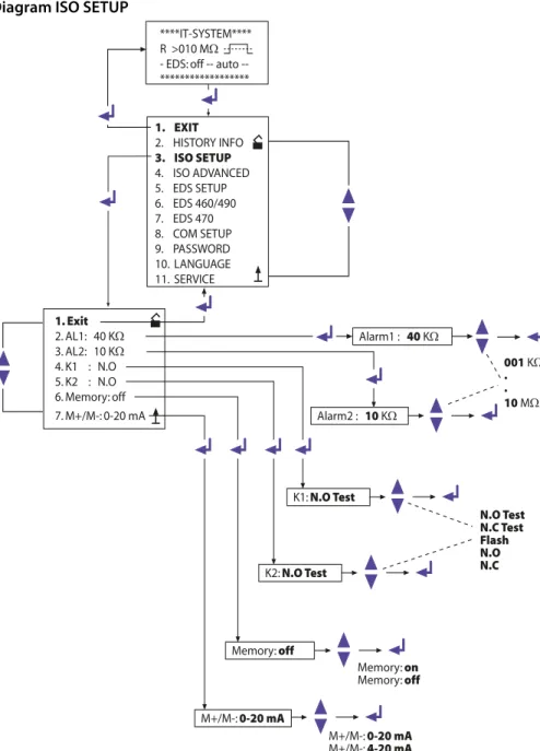
5.4 ISO SETUP menu: Setting of the basic ISOMETER® functions
The response values (Alarm 1/2, prewarning and main alarm), the operating principle of the alarm relays K1 and K2 (N.O = N/O operation, N.C = N/C operation), the fault storage behaviour and the selection of the current output between two different ranges are set in this menu.5.4.1 Response values Alarm 1 and Alarm 2
The response values Alarm 1 and Alarm 2 are selected with the UP/DOWN keys and stored with the ENTER key.
5.4.2 Starting the EDS system via the response values ALARM 1 and ALARM 2
The EDS system is started when the value of the insulation resistance falls below the lowest preset response value, i.e. below both alarm values.
When setting the ISOMETER® response values, make sure that the lower value of them is within a range which the EDS system is able to find. Therefore it is recommended to set the ISOMETER® response value according to the response characteristic curves of the EDS system (Refer to Page 80).
5.4.3 Operating principle of the alarm relays
K1/K2 are factory set to N.O Test, that means N/O operation. When the supplement "Test" has been selected, the alarm relays switch over during a manual self test. If, for any reason, the alarm relays may not switch over during a manual self test, the settings N.C or N.O are to be selected.
K1: N.C Test = N/C operation contacts 11-12-14, with relay test (the alarm relay is energized during normal operation) K1: N.O Test = N/O operation contacts 11-12-14, with relay test
(the alarm relay is deenergized during normal operation) K1: N.C = N/C operation contacts 11-12-14, without relay test
(the alarm relay is energized during normal operation) K1: N.O = N/O operation contacts 11-12-14, without relay test
(the alarm relay is deenergized during normal operation) K1: Flash = Flashing function contacts 11-12-14
(the alarm relay and the LED flash in the event of an alarm message, approximately 0.5 Hz
Operation and setting
Diagram ISO SETUP
1. Exit
2. AL1: 40 KW
3. AL2: 10 KW
4. K1 : N.O 5. K2 : N.O 6. Memory: off 7. M+/M-: 0-20 mA
Alarm1 : 40 KW
Alarm2 : 10 KW
K1: N.O Test
K2: N.O Test
Memory: off
M+/M-: 0-20 mA
Memory: on
Memory: off
M+/M-: 0-20 mA
M+/M-: 4-20 mA
****IT-SYSTEM**** R >010 MW
- EDS: off auto --****************** N.O Test N.C Test Flash N.O N.C
001 KW . . 10 MW 1. EXIT
2. HISTORY INFO
3. ISO SETUP
4. ISO ADVANCED 5. EDS SETUP 6. EDS 460/490 7. EDS 470 8. COM SETUP 9. PASSWORD 10. LANGUAGE 11. SERVICE
Operation and setting
K2: N.C Test = N/C operation contacts 21-22-24, with relay test (the alarm relay is energized during normal operation) K2: N.O Test = N/O operation contacts 21-22-24, with relay test
(the alarm relay is deenergized during normal operation) K2 : N.C = N/C operation contacts 21-22-24, without relay test
(the alarm relay is energized during normal operation) K2 : N.O = N/O operation contacts 21-22-24, without relay test
(the alarm relay is deenergized during normal operation) K2 : Flash = Flashing function contacts 21-22-24
(the alarm relay and the LED flash in the event of an alarm message, approximately 0.5 Hz)
K3 has to be parameterized in the Menu EDS Setup, refer to Page 48.
5.4.4 Memory setting (on/off)
Memory: on = Fault memory is activated
The device must be reset with the RESET button after clearing the fault.
Memory: off = Fault memory deactivated (factory setting)
In the ISO SETUP menu the memory behaviour of the IRDH575 can be set. This setting does not have an effect on the memory behaviour of the connected EDS devices, these settings must be carried out in the EDS460/490 and EDS470 menu.
Operation and setting
5.4.5 Current output for external measuring instruments
Factory setting: 0…20 mA
The current output of the IRDH575 can be set to "0…20 mA" oder "4…20 mA" via the menu point "M+/M-:". The maximum load is 500 Ω.
Function 0…20 mA:
RF = insulation fault, I = current in mA Function 4…20 mA:
RF = insulation fault, I = current in mA
The associated characteristic curves are illustrated on page 76.
R
F=
20 mA x 120 kWI - 120 kW
R
F=
16 mA x 120 kWOperation and setting
5.5 ISO ADVANCED menu: Setting of the extended functions
5.5.1 External coupling device (AGH: no = factory setting)
Coupling devices cannot be connected to the IRDH575.
5.5.2 Selecting the system leakage capacitance range
This menu allows to select the maximum system leakage capacitance Cemax. You can select between two different ranges: 150 μF or 500 μF. Adaptation within the selected range is carried out automatically. Please note that the basic measuring time will be increased to approximately 10 seconds when the setting is Ce = 500 μF. Please also consider Cemax for the EDS-System, refer to curves at Page 81. Factory setting = 150 μF.
5.5.3 Changing the measuring principle from AMP to DC (Measure: AMP)
The DC measuring principle (reduced measuring time) is only suitable for pure AC systems. Factory setting = AMP.
5.5.4 Setting the repetition time for automatic self tests (Autotest: 24h)
The time for the repetition of automatic self tests can either be set to 1 hour or to 24 hours or can be deactivated. Factory setting = 24 h
5.5.5 Setting the real-time clock (Clock)
The setting of the real-time clock is the time base for the memory and for the automatic self test. In case of failure of the supply voltage, the real-time clock keeps running for approximately 30 days. When the device will be switched on after this period, a flashing "C" appears on the display and the clock has to be set again.
5.5.6 Setting the date (Date)
As well as the time, the date is required for the memory, too. In the event of power supply failure, the date function is not influenced for at least 30 days. If the device is switched on again after this period, a new setting of date and time of the real-time clock is required.
5.5.7 Specifying the starting time of the automatic self test (Test)
If the 24h self test is activated in the ISO ADVANCED menu, it is possible to set the time (hour) when the self test is to be carried out by means of the "TEST: 12:00" sub menu. Then the self test is automatically carried out once a day at a given time. If the 1 hour auto test has been selected, the self test will be carried out at every full hour.
Operation and setting
5.5.8 Diagram ISO ADVANCED
1. Exit
2. AGH: no 3. Ce max : 150µF 4. Measure: AMP 5. Autotest: 24h 6. Clock: 21:09 7. Date: 01.01.01 8. Test: 12:00
Ce max : 150µF
Ce max : 150µF Ce max : 500µF ****IT-SYSTEM****
R > 010 MW
- EDS: off auto --******************
Autotest: 24h
24h no 01h
Clock: 21:09
Date: 01.01.01
Test: 12:00
Test: 00:00 . . .
Test: 23:00
Measure: AMP
DC AMP 1. EXIT
2. HISTORY INFO 3. ISO SETUP
4. ISO ADVANCED
5. EDS SETUP 6. EDS 460/490 7. EDS 470 8. COM SETUP 9. PASSWORD 10. LANGUAGE 11. SERVICE
Operation and setting
5.6 EDS-SETUP menu: Settings for fault location
This menu allows to carry out the necessary settings for the insulation fault location system (EDS).
5.6.1 EDS auto / on / off / pos / 1cycle
A selection of the start and stop conditions for EDS systems and their meaning are listed below:
on
The EDS is running continuously, regardless of the insulation value and the alarm messages from the ISOMETER®. This setting is essential, for example, for mobile insulation fault location systems such as EDS3060/3360.
off
The EDS system is constantly switched off. pos470 (EDS47… only)
For continuous measurement at a desired address (EDS4...-12) and a certain channel. The selected parameters are kept until a new operating mode is set. This function is only possible in the Master mode (bus address 1).
The following messages are possible in the POSITION mode.
Note: the messages noCT and short are only generated when the CT monitoring for the respective channel has been switched on (= factory setting, menu CT SETUP):
– no EDS: no EDS47... of this address available – no Alarm: no insulation fault detected
– … mA: indication of the fault current in case of an insulation fault – >1A/>10 A: AC residual current > 1 A (EDS473) or >10 A (EDS470) – peak fault: measurement disturbed
– short: CT input short-circuited
Operation and setting
5.6.2 Diagram EDS-SETUP
1. Exit
2. EDS: auto 3. System: 3AC 4. MaxPuls: 025mA 5. K3 Alarm: on
EDS : auto
System: 3AC
MaxPuls: 025mA
1 mA 2,5 mA 10 mA 25 mA 50 mA auto on off pos470 1cycle 3AC AC DC POSITION SETUP ADR: 002 k: 001
no EDS/ 15mA/ >1A/ >10A ****IT-SYSTEM****
R > 010 MW
- EDS: off auto --******************
1. EXIT
2. HISTORY INFO 3. ISO SETUP 4. ISO ADVANCED
5. EDS SETUP
6. EDS 460/490 7. EDS 470 8. COM SETUP 9. PASSWORD 10. LANGUAGE 11. SERVICE
K3 Alarm: on on off
Operation and setting
1cycle EDS47… :
As soon as the insulation resistance has fallen below the ISOMETER® response values ALARM 1 and 2, the EDS system is automatically activated once. It remains active until every EDS47… has measured all channels once and as long as the test current during the measurements is above 1.5 mA (EDS470) or 0.15 mA (EDS473). EDS46… / 49… :
As soon as the insulation resistance has fallen below the ISOMETER® response values ALARM 1 and 2, the EDS system is automatically activated once. It remains active for approximately 5 minutes when the test current during the measure-ment is above 1.5 mA (EDS460/EDS490) or 0.15 mA (EDS461/EDS491). auto
As soon as the insulation resistance has fallen below the ISOMETER® response values ALARM 1 and 2, the EDS system is automatically activated for approxi-mately 5 minutes and remains activated as long as the test current is above 5 mA (0.5 mA). The EDS insulation fault location process is cyclically interrupted for approximately 5 minutes (factory setting), i.e. for the time the ISOMETER® is carry-ing out insulation fault measurements.
5.6.3 System DC / 1 AC / 3 AC
The type of the system to be monitored are to be selected from this sub menu: DC = DC system
1 AC = single phase AC system 3 AC = three-phase AC system Factory setting is 3AC!
5.6.4 maxPuls 1 / 2.5 / 10 / 25 / 50 mA:
This setting determines the maximum test current.
1 and 2.5 mA for EDS473 / 461 / 491 systems, preferably 2.5 mA.
1mA is recommended when sensitive electrical equipment is supplied by the system, such as PLC controllers.
Do not use these settings for supply voltages > 575 V.
Otherwise test currents up to 7 mA can occur, which can damage sensitive equipment.
Operation and setting
10, 25 and 50 mA for EDS470 / 460 / 490 systems, preferably 25 mA. 10 mA is recommended when sensitive equipment such as control relays is supplied by the system. 50 mA should only be used in case of systems involving a lot of parallel faults (factory setting 25 mA).
The test current of the IRDH575 is factory set to 25 mA.
Resulting from the type of supply system, the real test current in AC systems is lower than the setting. The reduction factor is 0.5 in AC-Systems and 0.67 in 3AC systems. Therefore, the test current setting 1 mA for EDS473 and
10 mA for EDS470 devices is not admissible in AC systems.
A list of possible test current settings for IRDH575 in relation to the type of supply system and insulation fault evaluators is given in the table below:
* = Set the response value of EDS460/490 to < 5 mA (TGH1394, Chap. 6.6.3.2)
** = Set the response value of EDS461/491 to < 0.5 mA (TGH1394, Chap. 6.6.3.2)
Test current limiting for supply systems < 40 V
Please note that the test current is to be set according to the type of supply system.
Type of supply system
EDS460/490 min. max.
EDS461/491 min. max.
EDS470 min. max.
EDS473 min. max.
DC AC 3AC
10 mA 50 mA 10 mA* 50 mA 10 mA* 50 mA
1 mA 2,5 mA 1 mA** 2,5 mA 1 mA** 2,5 mA
10 mA 25 mA 25 mA 25 mA 25 mA 25 mA
1 mA 2,5 mA 2,5 mA 2,5 mA 2,5 mA 2,5 mA
Please note:
In supply systems to be monitored with a voltage < 40 V the maximum test current of all IRDH575B1… versions is limited to
Operation and setting
5.6.5 K3 alarm: ON
The K3 relay can be used either for one or for two functions. It is always used for signal-ling IRDH575 device errors.
K3 alarm: on
= K3 signals additionally occurring EDS alarms as common alarm. Please note that this function is only active in the master mode (BMS address 1 = factory setting).
K3 alarm: off
= K3 only signals IRDH575 device
Operation and setting
5.7 EDS460/490 menu
This menu can only be opened in the master mode (bus address 1), all the settings via the BMS bus can only be carried out in the master mode, even when several IRDH575 are interconnected. After starting the menu, the IRDH575 queries the essential param-eters of EDS46… / EDS49… and the current paramparam-eters appear on the display.
5.7.1 General
The following parameters have an effect on that device the BMS address of which is be-ing displayed. Set the address in order to select the appropriate device.
Memory
Use this menu option to switch the fault memory of the selected EDS46…/EDS49… on or off. Factory setting = off.
Trigger
Use this parameter to specify whether the fault location of EDS46… / EDS49… is to be started by an IRDH575 (Com) or if automatically and continuously all measuring chan-nels are measured in parallel (Auto). Factory setting = Com.
N. freq
Use this menu option to select the nominal frequency of the system to be monitored. You may select 50, 60 or 400 Hz. Factory setting = 50 Hz.
System
Use this menu option to select the type of the distribution system to be monitored. You may select:
DC = DC system
AC = single-phase AC system 3 AC = three-phase AC system Factory setting = AC.
5.7.2 Channel
The following parameters have an effect on the device the BMS address and measuring channel of which is being displayed. Set the respective address and channel in order to select the appropriate device.
Operation and setting
Diagram EDS460 /490 with General and Channel
1. Exit
2. General 3. Channel 4. Relay: N/O 5. Test/Reset
5. EDS SETUP
6. EDS 460/490
7. EDS 470 8. COM ETUP
ADR: 2...90 Sw: V1.02 1. Exit
2. Memory: off 3. Trigger: Com 4. N.freq.: 50 Hz 5. System: AC
on
off Memory: on
Com
Auto Trigger: Auto
DC 50 Hz
60 Hz
400 Hz
N.freq.: 60 Hz
AC DC
3AC
Systeme: 3AC
ADR: 2...90 CH: 1...12 1. Exit
2. ResVal: 0004 mA 3. CT: W/WR 4. T(on) :00 s 5. T(off) :06 s 6. CTmonitor: on 7. Inverter: off 8. Op. mode: N/O
W/WR WS P52 P165 P20 off
CT: off
2...
10mA ResVal: 0005 mA
00 s 06 s
12 s 18 s
24 s
T(on) : 12 s
T(off) : 18 s
on
off CTmonitor: off
on
off Inverter: on
see next page
Operation and setting
ResVal
Use this menu option to set the response values of the EDS device to be parameterized. This applies to:
EDS460 / EDS490: 2…10 mA in 1 mA steps, factory setting = 5 mA EDS461 / EDS491: 200…1000 μA in 1 μA steps, factory setting. = 500 μA
CT: W/WR
Select the measuring current transformer type to be used from the list below:
W/WR = circular or rectangular measuring current transformer = factory setting WS = split-core current transformer
off = channel switched off
T(on)
Use this menu option to set a response delay of 0…24 s for the selected EDS4… Factory setting = 0 s.
T(off)
Use this menu option to set a delay on release of 0…24 s for the EDS4…; Factory setting = 6 s.
CT monitor
To enable or disable the CT monitoring. That enables the EDS... to check the proper con-nection of the respective measuring current transformer. After the test, this will be indi-cated on the display as described in Chapter 5.7.4 EDS Test. Faults are indiindi-cated by the "Alarm 1“ LED. In position "off“, this function is deactivated.
Factory setting = on.
Inverter
Use this menu option to adapt a selected channel of the EDS46… /49… to a circuit com-prising a frequency converter; Factory setting. = off.
Op.mode
Use this menu option to determine the operating mode of the 12 channel-related alarm relays of an EDS490 / EDS491; Factory setting = N/O.
5.7.3 Relay
Use this menu to set the parameters for common alarm and system fault alarm at the relays of EDS46… and EDS49. The following parameters have an effect on that device the BMS address and the associated alarm relay of which are being displayed. Set the address and the respective relay /1,2) in order to select the appropriate device.
Operation and setting
Op.mode
Use this menu option to set the operating mode of the common relays for alarm 1 and alarm 2. Factory setting: Relay 1 = N/O, Relay 2 = N/C.
ALARM
Use this menu option to assign an occurring EDS alarm to one or both EDS alarm relays. Factory setting for Relay 1/2 = on.
Dev. Error
Use this menu option to assign an occurring EDS device fault alarm to one or both EDS alarm relays. Factory setting. Relay 1 = off, Relay 2 = on.
In case of fault the following fault messages appear on the display of the IRDH575: no CT (measuring current transformer not connected)
short (measuring current transformer short-circuited) AC residual> 1 A (EDS461 /EDS491)
AC residual> 10 A (EDS460 /EDS490)
5.7.4 EDS Test
After activating this menu option, the IRDH575 checks all BMS bus nodes displaying the following details:
Device address Device type Software version CT connection
at EDS47… means:
– ok = channel switched on – off = channel switched off
– noCT = no measuring current transformer connected – short = measuring current transformer short-circuited Memory behaviour of the EDS47... (Memory on/off) Operating principle of the alarm relays of EDS47... (N.O/N.C)
If one of the tested BMS devices does not provide the required properties, no answer is shown in the list of properties.
Factory setting = off.
5.7.5 EDS Reset
Operation and setting
Diagram EDS46... /49... with Relay, EDS-Test and EDS-Reset
1. Exit
2. General 3. Channel 4. Relay: N/O 5. Test/Reset
6. EDS 460/490
7. EDS 470 8. COM SETUP
ADR: 2...90 Relay: 1...2 1. Exit
2. Op. mode: N/O 3. Alarm: off 4. Dev. Error: on
on
off Dev. Error: off N/C
N/O Op. mode: N/C
on
off Alarm: on see previous page
on
off EDS Test: on
ADR: XXX k: XX TEST EDS460 V2.10 CT: noCT Mem: off busy .... 16 s
on
off EDS-Reset: on
1. Exit
2. EDS Test: off
Operation and setting
5.8 EDS 470 menu
This menu can only be opened in the Master mode (bus address 1). When several IRDH575 are interconnected via the BMS bus, all these settings can only be carried out with a Master device.
5.8.1 EDS Monitor
Indication of all detected insulation faults signalled to the IRDH575 via the BMS bus by the connected EDS devices. The second line of the display shows the respective number of an alarm as well as the total number of alarms. The third line shows the address and the channel of the insulation fault evaluator EDS4… as well as the measured test current.
5.8.2 EDS Test
IRDH575 checks all BMS bus nodes and indicates the following details: Device address
Device type Software version CT connection
in case of EDS47… means: – off = channel switched off
– noCT = no measuring current transformer connected – short = measuring current transformer short-circuited Memory behaviour of the EDS47… (Memory on/off)
Elongation of the measuring time EDS47… (peak 1…255) in case of measure-ment disturbances
Operating principle of the alarm relay EDS47… (N.O/N.C)
5.8.3 EDS Reset
This menu point can be used to reset stored fault messages of the connected EDS devices.
5.8.4 Details about the menu points Relay, Memory and n-peak
The parameters indicated on the IRDH575 display do not necessarily correspond to the EDS47... settings. Only when a control command is sent to EDS by pressing Return, the EDS settings of EDS47… correspond to the IRDH575 indication.
Operation and setting
5.8.5 Diagram EDS 470
1. Exit
2. EDS Monitor 3. EDS Test: off 4. EDS Reset: off 5. Relay: N/O 6. Memory: on 7. CT Setup 8. n-peak: 1...255
EDS-Test: off
5. EDS SETUP 6. EDS 460/490
7. EDS 470
on off
****EDS-Monitor**** Nr.: 01 #Nr.: 02 ADR: 03 k12 20mA *********************
EDS-Test: on
ADR: XXX k: XX TEST EDS470-12 V2.10 CT:noCT Mem: off peak: 255 Rel: N/O busy .... 16 s ****CT-SETUP****
ADR: 2....90 k: 1....12 Typ: standard/split /off conn.-CT: on/off
4. EDS Reset: off 5. Relay: N.O 6. Memory: on
Nr: 01 01...50
EDS-Reset: off
on
off
EDS-Reset: off
Relay: N.O
N.O
N.C
Relay: N.C
Memory: on
off
on
Operation and setting
5.8.6 Relay
Operating principle of the alarm relays of EDS47…: N.C = N/C operation
N.O = N/O operation = factory setting
5.8.7 Memory
Setting of the memory behaviour of EDS47… The factory setting is „on“.
When the memory is in "on" position, the alarms of an EDS47… are maintained until a RESET is carried out via the menu (IRDH575) or the RESET key is pressed on the EDS47…
When the memory if in "off" position, the alarm stored in the EDS47… will be deleted when the next scanning is carried out, provided that no insulation fault exists and no insulation fault location process is running.
5.8.8 CT Setup:
Setting of the CT type and connection monitoring for EDS47…: ADR:
Setting the BMS address of an EDS47… that is to be configured. k:
Setting the BMS channel that is to be configured.
Note:
When ADR:2-90 and k:1-12 are selected, the same CT type will be set for every channel of every device address.
Type:
– standard = measuring current transformers of circular and rectangular type = factory setting
– split = split-core measuring current transformers – off = channel switched off
conn.-CT
On or off switching of the CT monitoring Factory setting is „on“.
The CT connection monitoring of the EDS4…-12 recognizes whether a measuring current transformer is correctly connected. This will be indicated on the display after a test has been carried out as described in Chapter 5.8.2 EDS Test. In "off position" this function is deactivated.
Operation and setting
5.8.9 n-peak:
n-peak: 1-255
Setting of the maximum automatic elongation of the measuring time of the connected EDS47…if disturbances are likely to occur in the system being monitored. By default, four measurements are carried out per channel before the EDS47… proceeds to the next channel.
If disturbances occur during the measurement due to system interferences ( signalled by the "Fault"-LED at EDS47…), the number of measurements per channel will automatically be increased by the preset number n, that means 4 + n measurements per channel are carried out in this case. The n-times elongation of the measuring time per channel will automatically be stopped, when the fault is eliminated.
Factory setting is n = 5.
The functions of the EDS470menu and the position mode in the EDS SETUP menu is not available in the Slave mode!
Operation and setting
5.9 COM SETUP menu: Setting the BMS interface
5.9.1 Bus address (Addr: )
This menu item is used to set the BMS bus address of the IRDH575. Take care that the bus address is not assigned twice.
The device is factory set to address 1 and hence acts as a Master.
5.9.2 ISO Monitor
This function allows to query the current measured value as well as the messages of all bus-capable ISOMETER®s existing in the BMS network. After selecting the bus address, the entire information stored by the selected device is indicated on the display The display indication is structured similar to the standard indication, but instead of the indication of the measuring pulse, the selected bus address is indicated. Without press-ing a key, the indication changes to the standard indication of the IRDH575 after about five minutes.
If there is no information available from the selected ISOMETER®, the message "!!!!NO DATA!!!!" will be displayed.
Information is being searched: No data found:
Current data address 03:
If several IRDH575 are operated on one BMS bus, the addresses of other ISOMETER®s must be assigned one after the other, since only one device may represent the Master.
<<BUS SCANNING>> R= ADR:02 ! ! ! ! N O D A T A ! ! ! ! R= ADR:02 I n s u l a t i o n Fa u l t R= 010KW ADR:03