A Hardware Architecture for Scheduling
Complex Real-Time Task Sets
*Sergio S´aez , Joan Vila , Alfons Crespo and Angel Garcia
+DISCA, Universidad Polit´ecnica de Valencia, Spain
+Departament of Electrical Engineering, Universidad del Valle, Cali, Colombia
The problem of jointly scheduling both hard deadline pe-riodic tasks and soft apepe-riodic tasks has been the subject of considerable research in real-time systems. One of the most widely accepted solutions for this problem are slack stealing algorithms. However, these algorithms are rather impractical, since they all imply a considerable scheduler overhead. This paper faces the overhead prob-lem by introducing a complete hardware architecture that implements slack stealing in hardware using an optimal algorithm redesigned to be implemented efficiently in hardware. The proposed solution is a circuit that behaves as a kind of sophisticated interrupt controller taking the task workload and the interrupts as inputs, and providing the highest priority task to be executed in the CPU. From the point of view of hardware design, the algorithm involves two main problems: first, to select the highest priority task at every moment and, second, to locate a set of slack gaps in a real-time computation.
Locating slack gaps in a real-time computation is a problem that requires to “look forward in time” into the forecast schedule of a given workload. This paper analy-ses the different approaches for solving this problem and presents a novel architecture to solve it efficiently using a technique based on an event-driven simulation of the future of a real-time computation. A timing analysis of the proposed design is also presented.
1. Introduction
The workload of a real-time system can be ex-pressed, in general, as a task set composed by a mixture of periodic, and aperiodic tasks. The problem of jointly scheduling hard periodic tasks and soft aperiodic tasks has been subject of considerable research in the last years. As a result, there are several solutions with dif-ferent performance/cost ratios. Among the
proposed solutions 1, 29] are the background server, the polling server, bandwidth preserv-ing servers 12, 27, 28, 8, 6] and slack steal-ing algorithms 11, 17, 29, 20]. Most of the proposals that claim to be optimal, are highly complex and would imply a significant tempo-ral execution overhead. The main reason for this overhead is the need to look forward into the periodic tasks schedule in order to locate the processor quanta(gaps)where aperiodic tasks can be executed. An approach to reduce this overhead is to provide the run-time scheduler with some tables, elaborated off-line, with the locations of the processor gaps. This method has two disadvantages: first, the spatial cost of the tables and, second, the processor time that is wasted in the (usual) case when tasks have an execution time that is lower than its nominal WCET(worst-case execution time).
The approach followed in this paper to reduce the scheduling overhead is to do scheduling in hardware. The selected algorithm for its hard-ware implementation is a variation of the Dy-namic Slack Stealer by20] that has been spe-cially adapted to be implemented in hardware
23]. This algorithm is optimal in the sense of minimising the response time of aperiodic tasks without jeopardising the deadlines of periodic tasks. The paper presents a complete hardware implementation of the EDF scheduler and the DSS algorithm. As it is a completely on-line version of the algorithm, no pre-calculated slack table is needed and, therefore, the spatial
com-This work was supported by the Spanish Government Research Office(CICYT)under grant TIC99–1043–C03–02.
plexity of such slack tables is avoided29, 20]. Furthermore, all dynamic workload variations, such as periodic or sporadic tasks with stochas-tic execution times (gain time), can be taken into account when slack time is calculated. Most of the literature about hardware imple-mentation of schedulers comes from the field of packet scheduling and packet multiplexing in real-time networks. In these systems schedul-ing is always done in hardware since efficiency is crucial. Packet scheduling in real-time net-works is mostly based on priorities, as it happens in processors scheduling, but the Rate Mono-tonic (RM) theory is not so straightforward to apply in this case 26]. The key aspect of the hardware implementation of priority poli-cies is the hardware design of priority queues. Static priorities scheduling can be implemented with a fixed number of FIFO queues, one for each priority level. An efficient application of the RM theory requires as many as 256 prior-ity levels. The paper by Moon, et al. 15], reviews several architectures for implementing priority queues in hardware and includes a com-parison of the four main existing approaches: binary trees of comparators, priority encoders with multiple FIFO lists, shift registers and sys-tolic arrays. An alternative scheme is 9] that uses an associative memory(CAM)to store pri-ority information, and RAM for data storage. Most of these works deal with fixed priorities. The complexity of hardware implementations significantly increases in the case of dynamic priorities, since it requires a scheme for updat-ing priorities and for reorderupdat-ing of packets on a per cycle basis. That can severely degrade the performance of conventional priority queue design. The performance of a given queue de-sign for a particular problem has been analysed throughout different papers.
Some examples can be found in 18] address-ing the design of real-time router usaddress-ing a com-parator tree, in13]presenting an implementa-tion called Rotating Priority Queues(RPQ)that provides an efficiency similar to EDF schedul-ing with a complexity of RMS, in 31] ad-dressing the problem of updating priorities in Fair Queueing algorithms, in10] presenting a conceptual multi-channel EDF queue for ATM switching and in16]presenting a novel VLSI Priority Packet Queue(PPQ)that achieves fast operation by manipulating packets instead of
isolated words. Some papers also address the problem of full queues25, 16].
In the field of real-time processing, hardware scheduling is not so usual as in packet switching, but there are also some proposals of real-time coprocessors. The ATAC coprocessor22] pro-vides support for Ada tasking including schedul-ing, precise delay implementations, and inter-rupt handling. Scheduling is based on the RM theory and provides 64 priority levels and pri-ority inheritance for shared objects. Colnaric and Halang 5] introduce the idea of a kernel coprocessor that is responsible for all operat-ing system services. The design is structured into two layers: a Primary Reaction Layer, that handles all external events, and a Secondary Re-action Layer, responsible for operating system requests. From the point of view of scheduling, dynamic scheduling (EDF) is implemented in hardware 4], since it offers a number of ad-vantages over RM, as discussed in7]. Finally, the Spring kernel30]introduces a sophisticated coprocessor for a dynamic distributed real-time system where no periodic workload is known in advance. It provides support for multipro-cessor scheduling(completely based on heuris-tics), feasibility checking and task migration
14]. This paper assumes a different model and presents hardware support for a system where the static workload, formed by a set of periodic tasks, is scheduled using EDF and the dynamic workload, modelled as aperiodic tasks, is sched-uled using a slack stealer. The main contribution of this scheme is how to perform slack stealing in hardware.
The rest of the paper is organised as follows: section 2 presents the basic hypothesis and prob-lem formulation, section 3 revises the method for slack stealing, section 4 introduces the hard-ware architecture and the design of its build-ing blocks, section 5 discusses the problem of the clock frequency and, finally, section 6 con-cludes and points out future work.
2. Problem Formulation
aperiodic tasksJ with no deadlines, to be exe-cuted on a uni-processor system, the goal of the paper is to design a hardware circuit that sched-ules this workload in the way that minimises the response of aperiodic requests and accepts, whenever possible, sporadic tasks without jeop-ardising the deadlines of periodic tasks.
The periodic taskT is defined byT = fTi(Ci Di Pi) : i = 1 ngwith 1 Ci Di Pi, whereCi,DiandPiare the worst-case execution
time, relative deadline and period of the taskTi,
respectively. The task setT is assumed to be feasible21].
The sporadic task setS can be defined asS =
fSi(Ai Ci Di) : i = 1 igwith 1 Ci Di, whereAi,Ci andDiare the arrival time,
worst-case execution time and deadline of sporadic taskSi, respectively. We assume that the arrival
timeAi of each sporadic task is unknown, and
that Ci and Di become known at Ai upon the
arrival of Si. At time Ai, the task Si must be
accepted or rejected if its deadline cannot be guaranteed.
Similarly, the aperiodic task set J can be de-fined as J = fJi(Ai Ci) : i 1g, where the definition and assumptions for Ji are the same
that as forSi, but taking into account thatJihas
no deadline, and it cannot be rejected.
The workload at a given instantI0is represented by a set of active tasks A(I0) that defines the outstanding computation, a set of inactive peri-odic tasksT(I0), and the current aperiodic task queueJ(I0).A(I0)is composed of all periodic activations and already accepted sporadic tasks that are unfinished by timeI0.
The tasks do not suspend themselves or syn-chronise with other tasks and they are ready for execution as soon as its activation occurs. The circuit that performs the required schedule for the described workload behaves as a kind of sophisticated interrupt controller. The hard-ware/software interface is defined as follows:
On startup time, the software writes all the task attributes(Ci Di Pi) into the hardware registers.
When a sporadic task arrives, the hardware must perform a feasibility test in order to ac-cept or reject the task if its deadline cannot be guaranteed.
When an aperiodic task finishes its execution or a periodic task suspends itself until the next period, the software writes the task id of that task into the hardware.
When a context switch should occur, the hard-ware issues an interrupt and provides the soft-ware with an output register that indicates the task id to be executed next.
The controller maintains all the task sets, and calculates the slack gaps and it provides an in-terrupt only when necessary. The software com-ponent of the scheduler is, thus, reduced to the minimal expression, acting only as CPU dis-patcher.
3. Algorithm for Dynamic Slack Stealing
This section presents a brief overview of the al-gorithm for implementing Dynamic Slack Steal-ing(DSS)algorithm in hardware. The founda-tions of this algorithm are in the analysis of EDF scheduling by Ripollet al. 21].
The first concept that needs to be introduced is the definition ofslack gap.
Definition 3.1. For a given feasible task setT, the slack gaps are the intervals of idle time in the schedule ofT that hold when active tasks of
T are processed as late as possible.
Slack gaps were first characterised by Chetto and Chetto3], for task sets with deadlines equal to periods. Ripollet al. 20]showed the slack time characterisation for periodic tasks with deadlines lower than periods. In their work, a formal method to construct the list of slack gaps is presented. This analysis introduces two functionsGT
(t)andH T
(t)which are key to the whole development. These two functions will have to be calculated in hardware in the design presented in this paper.
FunctionG T
(t): Given a task setT, function GT
(t)accumulates the amount of computing time required by all activations of tasks inT from time zero until timet. Formally:
GT (t)=
n
X
i=1 Ci Pt
i
Function H T
(t): Given a task setT, func-tionHT
(t)is the amount of computing time required by all activations of tasks inT whose deadline is less than or equal tot. Formally:
HT (t)=
n
X
i=1 Ci
t+Pi;Di Pi
In other words,HT
(t)represents the amount of computing time that the scheduler should have served until timet in order to meet all deadlines.
For the sake of clarity, these functions are de-fined for a synchronous task setT, where all the periodic tasks start at time zero, but they can be easily extended to useT(I0)A(I0)19]. Figure 1 shows functionsGT
(t)and H T
(t)for the task setT =fT1 = (1 3 6),T2 =(4 10 10), T3 = (4 10 17)g. Note that G
T
(t) is a stepped function with steps in the beginnings of new periods(0 6 10 12 17 18 20 :::)while HT
(t) is also a stepped function with steps in deadlines(0 3 9 10 15 20 21 27 :::). Note also thatGT
(t)H T
(t)8t.
Fig. 1. GT
(t)andH T
(t)Examples.
Using these functions, slack time can be char-acterised as follows:
Lemma 3.1. For a given feasible task set T, the slack time at time I0, STT
(I0), can be ob-tained as:
STT
(I0)= min 8tI0
(t;H T
(t))
For any feasible set of periodic tasksT uled according to any optimal preemptive sched-uler, the slack timeSTT
(I0)represents the max-imum time that can be used to service aperiodic tasks until timeI0, without jeopardising the hard deadlines of the periodic tasks.
Once the slack time has been formally char-acterised, the next step is to obtain a list of slack gaps. An important property shown in
20]is that these gaps always start whereH T
(t) changes its value (a step in H
T
(t)). This is a necessary(but not sufficient)condition for the beginning of a slack gap. LetVibe the instants
whereHT
(t)takes a step. To confirm that some Vi is the beginning of a slack gap, it has to be
checked that:
69Vj :(Vj>Vi)^
(Vj;H T
(Vj))<(Vi;H T
(Vi))
This requires to search forward into the values of HT
(t) to confirm the beginning of a slack gap. Fortunately this search is bounded, as it will be shown shortly.
Another interesting aspect is the length of a slack gap. Let βi be the beginning of a slack
gap. The length of slackβirequires to know the
beginning of the next gap, that is βi+1, and is given by:
length(βi)=∆i +1
;∆iwith∆i =βi;H T
(βi)
If the algorithm is looking for an amountS0 of slack time, its confirmation time is defined as:
Definition 3.2. For a given feasible task set T, and an amount of slack timeS0, the confir-mation instantCI(S0)is defined as: CI(S0) = min(t):t >0] ^ t;G
T
(t)=S0]
and this confirmation time is bounded, provided this slack time exists.
Lemma 3.2. For any feasible task set T, and an amount of slack timeS0, it can be asserted that: 69t :t >CI(S0)] ^ t;H
T
This property indicates that the minimum of the functiont;H
T
(t)is reached beforet;G T
(t) matches the current minimum, and therefore it limits the search range for the confirmation con-dition.
These definitions show how a list of slack gaps can be constructed for a given task setT. Equiv-alent definitions can be done, but using the task set at given instantI0,T(I0)A(I0).
Consider the above example shown at figure 1 where a periodic task setT = fT1 =(1 3 6), T2 = (4 10 10),T3 = (4 10 17)g is repre-sented. For such task set, the instant of time where HT
(t) takes steps are: Vi = (0 3 9 10 15 20 21 27 :::)The beginnings of slack gaps are: βj =(10 15 30 33 :::), and the list of slack gaps, with their corresponding lengths:
θ = f(10 4) (15 1) (30 2) :::g. The grey boxes at the bottom of the figure show where the slack gaps are located(θ).
4. Hardware Design
According to the previous section, it can be stated that the goal of a hardware coprocessor for slack stealing will be to compute the start and the length of the slack gaps in a real-time computation in order to satisfy the requirement for a given amount of slack time. As shown, that requires to search forward in time, looking for the instants of time that meet the slack time characterisation. Once a gap is suspected, the search has to continue until reaching the confir-mation time, but fortunately the search depth is bounded. Suspecting and confirming slack gaps require to compute functionsGT
(t)and H T
(t) for every instant of time that is inspected. This section describes the architecture to per-form this search into future instants of time of a real-time computation. Two approaches have been devised to achieve this goal:
Tick-oriented. In this approach time is incre-mented by one in each iteration, checking for the start of gaps and the confirmation of gaps. So, finally, all future instants of time up to confirmation time are inspected.
Event-oriented. This approach is based on the idea that GT
(t) and H T
(t) are stepping functions, so it is not worth checking every
future instant of time, but only those where
GT
(t) and H T
(t) change value. These changes can be characterised by some well known events: HT
(t) takes a step when the deadline of some task is reached (so it evolves to inactive state) while G
T (t) changes when a task changes to ready state.
In our research both approaches have been stud-ied. The conclusion is that tick-oriented archi-tectures have the advantage of being more sim-ple(they can be implemented using a pipelined binary tree for example2])but they also have important drawbacks: the performance and the maximum depth search they can reach analysing future instants of time strongly depends on the granularity of the real-time clock. So if the unit of time is changed, say from milliseconds to microseconds, the implementation will per-form 1000 times slower. On the other hand, event-oriented architectures result in a greater complexity, due to event detection, but they are much more powerful. This section concentrates on the design and implementation of a event-oriented architecture for slack stealing in hard-ware.
The goal of the hardware design is to minimise the processor time wasted by the scheduler and interrupt handling which always results in de-lays and utilisation reduction.
The scheduler design has been split into a hard-ware component and a softhard-ware component, but the last one can be reduced to the minimal ex-pression. Their goals are:
The hardware maintains all the task sets, cal-culates slack gaps and informs the software component when a task reaches the maximum priority or an aperiodic task should start exe-cution.
The software component is only a CPU dis-patcher. It only needs to schedule the task indicated by the hardware, and inform the hardware when the current task finishes.
1. To select the highest priority task at every moment. In this case, the scheduling pol-icy follows the EDF basis, and therefore, the highest priority task is the ready task with the earliest deadline.
2. To calculate the HT
(t) and G T
(t) func-tions, as intermediate step towards aperi-odic task scheduling.
3. To calculate the set of slack gaps, in or-der to know when an aperiodic task can be scheduled or when an sporadic task can be accepted.
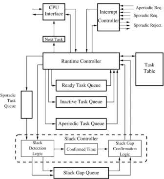
Fig. 2.Hardware Architecture.
Before describing this architecture, it is worth noting that there are two clocks involved in this hardware design:
Real-Time clock (RTC) The execution times are measured using this clock and it determines the processor quantum.
Hardware clock(HC)It determines how fast the hardware scheduler executes its in-ternal algorithms, and it is implementation dependent.
The main components of this architecture are related bellow:
Task table It is a memory that maintains the pa-rameters of the tasks, such periods, dead-lines, worst-case execution times (wcet), remaining execution time(ret), etc.
Ready tasks queue (hereafter RTQ)It contains all active tasks(A(I0) set)sorted accord-ing to the EDF policy. The active task with the highest priority is always at the head of the queue. It is also used to calculate theHT
(t)values.
Inactive tasks queue (hereafter ITQ) It con-tains the periodic inactive task set(T(I0)) sorted by activation time. The head of the queue is the next periodic task to be pro-moted to ready state. It is also used to calculate theGT
(t)values.
Aperiodic tasks queue It contains the aperi-odic tasks sorted according to the selected policy (FIFO, shortest job first, etc.). If that policy is preemptive, the run-time con-troller is informed whenever a preemption occurs between aperiodic tasks.
The aperiodic task queue can be imple-mented using well known static priority queues.
Run-time controller It is the main component of the system. It performs the sched-uler role, selecting the highest priority task from the active tasks queue and generating an interrupt towards the CPU whenever a context switch is required. It also calcu-lates functionsHT
(t)andG T
(t)necessary for slack detection.
Sporadic tasks queue It is a small queue that sorts all concurrent sporadic arrivals. The sporadic tasks are ordered according to the EDF policy, using a well known static pri-ority queue.
Slack gaps queue (hereafter SQG)It stores the slack gaps(θ), calculated from theViand Vi;H
T
(Vi)values.
Slack controller It calculates the slack gaps us-ing the slack gaps queue. The required values of theGT
(t)andH T
Interrupt controller It receives aperiodic and sporadic hardware requests, and informs the RT controller about these requests. If an sporadic request is rejected by the slack controller, it is conveniently signalled..
The main roles are carried out by the dynamic queues(RTQ and ITQ), the run-time controller and the slack controller. Their behaviour and implementation details are described next.
4.1. Dynamic Priority Queues
In this work dynamic priority queues are used for implementing the ready task setA(I0)(RTQ), and sorting the future activations of periodic tasks, i.e., the inactive periodic task set T(I0)
(ITQ). Several hardware structures have been proposed for implementing these queues, such as binary trees of comparators, shift registers or systolic queues. But, if the task priorities are dynamic, i.e., they depend on current time, an implementation problem arises: the task prior-ities should be updated every clock tick, and the highest priority should be reevaluated. This problem is not so important under the EDF ap-proach, since the head of the list can only change when new periodic activations occur or current running task finishes. According to this, several possible designs are possible:
To update task priorities (deadlines) only when periodic task activates or the current running task finishes.
To use absolute values for deadlines, i.e., deadlines values are related to a given fixed instant, calledzero.
To use relative values for deadlines, i.e, the value stored in every element is relative to the previous one and only the value at the head of the list is related to the current time. In the first approach the update overhead could be not negligible if the task set is large enough. The second approach requires wider registers and also introduces the overflow problem at the deadline registers, but it was successfully used at 10]. To avoid such problems, this paper advocates implementing in hardware a prior-ity queue with relative values similar to those queues used by the operating systems to han-dle multiple clock timers. With this approach, updating deadlines only requires to update the head of the queue.
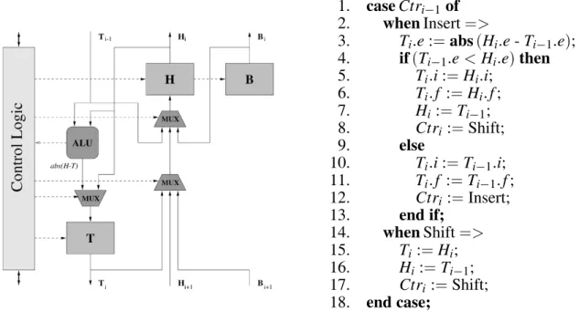
Implementation details Implementation of the above queue solution has been done using the systolic approach. This solution has the advantage that scales to a large number of pe-riodic tasks and priority levels. Furthermore, it also allows to obtain the highest priority task in constant time.
1. caseCtri;1of 2. whenInsert=>
3. Ti:e:=abs(Hi:e-Ti ;1
:e); 4. if(Ti
;1
:e<Hi:e)then 5. Ti:i:=Hi:i;
6. Ti:f :=Hi:f;
7. Hi:=Ti
;1; 8. Ctri:=Shift;
9. else
10. Ti:i:=Ti ;1
:i; 11. Ti:f :=Ti
;1 :f; 12. Ctri:=Insert; 13. end if;
14. whenShift=> 15. Ti:=Hi; 16. Hi:=Ti
;1; 17. Ctri :=Shift; 18. end case;
A dynamic priority queue is a systolic chain of
event cells, each of them containing registers
H, Ctr, B, and T. Register H is a compound register that stores the following values: a time event valueethat represents a deadline for RTQ or a task activation for ITQ, and is relative to the previous cell, a task identifierior pointer to the task table, a flag f indicating if it is a current event or a future one. Register Ctr is a com-mand control register. Register B is a backup register for storingH value before the start of a simulation and restoring it later(see below). RegisterT is a temporal register necessary for pipeline systolic behaviour. In addition, each cell contains an ALU to computeabs(H;T), i.e., the difference ofH:ewith respect the former cell. The algorithm shown in figure 3 describes, in VHDL notation, the insertion behaviour of a event cell. The length of ITQ should be equal to
the maximum number of periodic tasks, and the length of RTQ should be equal to the maximum number of periodic and sporadic tasks that can be active simultaneously.
4.2. Run-Time Controller
The main function of the run-time controller is to update the RTQ and ITQ when a CPU quantum ends and to calculateHT
(t)andG T
(t) functions to detect slack gaps. The values of these functions will be provided to the slack controller.
Updating RTQ and ITQ implies that when an in-active task reaches its period, the RT controller promotes it to the ready task set, and when the CPU informs that the current task has finished,
1. if(clockmod2=0)
2. min RTQ :=(RTQ.H.e<=ITQ.H.e); 3. if(min RTQ)then
4. min time :=RTQ.H.e; min ident :=RTQ.H.i; 5. if(RTQ.H.f=future)
6. func H :=func H+TTmin ident].wcet;
7. else
8. func H :=func H+TTmin ident].ret; 9. end if;
10. RTQ.Ctr :=Extract;
11. ITQ.H.e :=ITQ.H.e - min time; ITQ.Ctr :=None;
12. else
13. min time :=ITQ.H.e; min ident :=ITQ.H.i; 14. execution time=TTmin ident].wcet;
15. ITQ.Ctr :=Extract;
16. RTQ.H.e :=RTQ.H.e - min time; RTQ.Ctr :=None; 17. end if;
18. future time :=future time+min time;
19. SC.T :=future time; SC.H :=func H; SC.G :=func G; 20. else
21. if(min RTQ)then
22. ITQ.H.e :=TTmin ident].period;
23. ITQ.H.f :=future; ITQ.H.i :=min ident; 24. ITQ.Ctr :=Insert; RTQ.Ctr :=None;
25. else
26. func G :=func G+execution time; 27. RTQ.H.e :=TTmin ident].deadline; 28. RTQ.H.f :=future; RTQ.H.i :=min ident; 29. RTQ.Ctr :=Insert; ITQ.Ctr :=None; 30. end if;
31. end if;
Algorithm 1. HT
(t)andG T
the run-time controller extracts it from the ready tasks queue and, if it is periodic, it inserts a new instance into the inactive tasks queue.
Calculating the values of theHT
(t)and G T
(t) is done by simulating future states of the RTQ and ITQ. In order to maintain the current state of those queues (A(I0) and T(I0)), a backup system should be incorporated to the dynamic queue design.
TheHT
(t)andG T
(t)calculation section of the run-time controller is described by algorithm 1 using a notation close to VHDL. The algorithm notation is as follows:
RTQ.H: registerH(time event)of the head of RTQ
RTQ.Ctr :=Extract: Apply command Ex-tract to the control register of the head of RTQ.
TTn].wcet: register wcet(worst case ex-ecution time)of entrynof the task table.
SC.T: Register T of interface with the slack controller.
min RTQ: true when the closest event is a task deadline.
The rest of the notation is self explanatory. This algorithm simulates the future states by updating RTQ and ITQ at the speed of the hard-ware clock. Obtaining a new state requires two clock cycles. During the first cycle, the heads of RTQ and ITQ are inspected to find out the nearest event (deadline or activation) and the corresponding cell is dequeued. During the sec-ond cycle, a cell dequeued from RTQ during the first cycle is inserted in ITQ and a cell dequeued from ITQ is enqueued in RTQ. According to its definition, functionHT
(t)is updated in the first cycle every time the head of RTQ is dequeued. The initial value of HT
(t) is 0. Conversely, GT
(t) is updated every time that the head of ITQ is dequeued. However, note that in this case the calculation is done during the first cy-cle but the update is done in the second cycy-cle since GT
(t) changes its value at the end of a time interval. The initial value of GT
(t)is the sum of the outstanding execution times of all active tasks.
The simulation of future states is event driven
(not tick driven)so the time does not increment uniformly: once an event is processed, time is advanced by the value of the processed event. The run-time controller also informs the slack controller of the sporadic task arrivals in or-der to confirm them. All sporadic tasks that are confirmed are inserted into the RTQ, to be taken into account in future calculations. The aperiodic and sporadic tasks can be generated from software components by calling an operat-ing system primitive, or from hardware signals through theinterrupt controller.
4.3. Slack Controller
The proposed hardware scheduler also calcu-lates the set of slack gaps to know when the aperiodic and sporadic task can be scheduled without jeopardizing the hard deadlines of the periodic tasks.
In order to find the slack gaps, the slack con-troller uses the functionsHT
(t)andG T
(t) pro-vided by the run-time controller, and a special hardware queue, Slack Gaps Queue(SGQ), that calculates and stores the future slack gaps in a systolic fashion.
When a sporadic request arrives, the slack con-troller extracts the required slack gaps from the slack queue to find out if the sporadic task can be accepted. If the appropriated amount of slack time is available before the sporadic deadline, then the task is granted. If so, the sporadic task
1. if(clockmod2=1)then 2. ∆H :=T;H;
3. ∆G:=T;G; 4. else
5. if(∆G >confirmed time)then 6. confirmed time :=∆G; 7. end if;
8. if(T/=LastT)then
9. SGQ.TS :=LastT;
10. SGQ.TL :=Last∆H; 11. SGQ.Ctr :=Insert; 12. end if;
13. LastT :=T; 14. Last∆H :=∆H; 15. end if;
identifier is sent to the RT controller and in-serted into the ready tasks queue, to be taken into account in future calculations.
Whenever a slack gap is reached and outstand-ing aperiodic computation exists, the run-time controller is asked to generate a context switch interrupt.
The algorithm 2 shows the slack controller in VHDL notation. This algorithm basically tries to confirm slack time using the characteriza-tion of definicharacteriza-tion 2 in seccharacteriza-tion 3. It works in two phases. During the first phase, it computes
t ; G
T
(t), that represents an amount of con-firmed slack time, for a new step inHT
(t). In the second phase it determines the maximum of this function and inserts into the SGQ a new cell with the values of t and t;H
T
(t)for the recently processed step.
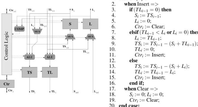
Implementation details of Slack Gaps Queue
The SGQ is also implemented as a systolic queue, where eachslack cellstores a slack gap, i.e. its start timeSiand its lengthLi, and a
con-trol command register, Ctr. Those values are relative to the end of the slack gap stored in the previous cell, except for the first cell.
The cell and the algorithm of this queue are shown in figure 4. The input values to the SGQ
are provided by the slack controller and consist of the current future timeVi, and the function
Vi;H T
(Vi)(∆i, ifViis the beginning of a slack gap). These values are inserted in the SGQ as TS and TL respectively. With these input val-ues, the SGQ constructs a list of presumed slack gaps that must be confirmed by using theGT
(t) function.
When the SGQ receives a new slack gap, ba-sically, what every cell does is make it relative to itself and pass arelative gapto the next cell. This meansTSi:=TSi
;1
;(Si+Li)andTLi:= TLi;1
;Li. If, during this iteration, the length of the relative gap becomes zero, then it indi-cates that the end of the queue has been reached and all outstanding cells are cleared. If, dur-ing this iteration, some cell of zero length or a length greater than the relative gap(produced by the previous cell)is found, then this cell sets its length to the length of the relative gap and the queue ends in the next cell.
5. Timing Analysis
Although some other methods, such as com-plex binary trees, can be used for implementing priority queues and also to calculateHT
(t)and GT
(t) values, the main advantage of the pre-sented method is that it performs an event driven
1. caseCtri;1of 2. whenInsert=> 3. if(TLi
;1
=0)then 4. Si:=TSi
;1;
5. Li:=0;
6. Ctri:=Clear; 7. elsif(TLi
;1
<LiorLi=0)then 8. Li:=TLi
;1; 9. TSi:=TSi
;1
;(Si+TLi ;1
);
10. TLi:=0;
11. Ctri:=Insert;
12. else
13. TSi:=TSi ;1
;(Si+Li); 14. TLi:=TLi
;1 ;Li; 15. Ctri:=Insert; 16. end if;
17. whenClear=> 18. Si:=0;Li:=0; 19. Ctri:=Clear; 20. end case;
simulation, so it calculates the values ofGT (t) and HT
(t) when they take a step, not continu-ously. This also avoids the problem with the real time clock granularity. This kind of stepped cal-culation is difficult to be calculated using other methods, since they would require to compute the step width first, and then the value incre-ment. For example, this calculation would need two steps of log2(N)cycles using a binary tree, whereN is the number of tasks.
The goal of this analysis is to determine the re-lation Real-Time Clock/Hardware Clock that allows to locate a given quantity of slack time
ST before it is needed. This allows aperiodic and sporadic tasks to be managed as soon as possible. More precisely, in order to obtain the minimum response time for a given aperiodic taskAi, the next slack gap should be located
be-fore the start time of the slack gap is reached. To do that, the worst scenario the hardware should be able to face would be to locate a slack time unit in only one real-time clock tick. On the other hand, In order to accept a given sporadic taskSiwith a computational requirement ofCi,
the quantity of slack time ST found before Si
arrives should be equal or greater thanCi.
Oth-erwise, the taskSishould wait until such
quan-tity of slack time could be found, and then be accepted or rejected.
In order to determine the relation Real-Time Clock/Hardware Clock, it is required to ana-lyze the work to be done in a real-time tick. It can be splitted in two parts:
1. To update RTQ and ITQ according to the Real-Time clock.
2. To extract the slack gaps queueθ by look-ing forward in time.
According to this, the latency of the hardware algorithm can be represented as:
L=tupdate+textract
The worst case for updating the queues is when all the periodic tasks are inactive and should be promoted from the ITQ to the RTQ. Thentupdate
can be stated as:
tupdate=2NtHC
whereNis the number of periodic tasks,tHC is
the period of the hardware clock, and the value 2
comes from the two cycle basis of the run-time controller algorithm.
On the other hand, as it was detailed in24], the worst case latency fortextractdepends on where
the worst case confirmation time for a given quantity of slack timeST is located. Such con-firmation timeRcan be calculated by using the recursive expressionRi+1
=G
T
(Ri+pS+ST) untilRi = Ri
+1, where R0
= 0, and pSis the slack timeusedon the previous RTC tick. The last value ofRiindicates the confirmation time
R. For the aperiodic case,pSandST should be set to 1.
Then, the worst case for extractingST units of slack time is:
textract= 2AtHC
where A represents the number of activations and deadlines within the interval0 R). That is:
A=
X
Ti2T
R+Pi;Di Pi
+
R Pi
6. Conclusions and Future Work
This paper shows the feasibility of implement-ing a complex schedulimplement-ing algorithm in hard-ware, which avoids completely the CPU schedul-ing overhead. The presented scheduler also shows a good scalability factor due to the sys-tolic design.
The paper describes how to efficiently imple-ment in hardware the following two important problems:
the systolic priority queues using relative time values, and
how to anticipate scheduling events using an event-driven approach and avoiding the real-time clock granularity problem.
References
1] N. AUDSLEY, A. BURNS, R. DAVIS, K. TINDELL,AND
A. WELLINGS, Fixed priority pre-emptive
schedul-ing: An historical perspective, The Journal of Real-Time Systems, 8(2/3):173–198, March/May
1995.
2] A. G. BANOS˜ ,Arquitecturas Hardware para
Plani-ficadores de Tiempo Real, PhD thesis, Universidad Polit´ecnica de Valencia, 1999. in Spanish.
3] H. CHETTO ANDM. CHETTO, Some results of the
earliest deadline scheduling algorithm,IEEE Transi-tions on Software Engineering, 15(10):1261–1269,
1989.
4] M. COLNARIC, D. VERBER, R. GUMZEJ ANDW. HA -LANG, Hardware-supported real-time operating
sys-tem kernel, Microprocessor and Microsystems, 18:579–591, 1994.
5] M. COLNARIC, D. VERBER, R. GUMZEJ ANDW. HA -LANG, Implementation of hard real-time
embed-ded control systems, Real-Time Systems Journal, 14(3):77–94, 1998.
6] T. GHAZALIE ANDT. BAKER, Aperiodic servers in
a deadline scheduling environment,The Journal of Real-Time Systems, 9:31–67, 1995.
7] W. HALANG ANDA. STOYENKO,Constructing
Real-Time Predictable Systems, Kluwer Academic Pub-lishers, Boston-Dordrecht-Lond, 1991.
8] N. HOMAYOUN ANDP. RAMANATHAN, Dynamic
pri-ority scheduling of periodic and aperiodic tasks in hard real-time systems, The Journal of Real-Time Systems, 6:207–232, 1994.
9] T. HSU AND L. KUNG, A hardware mechanism
for priority queue, Computer Arcitecture News, 7(66):162–169, December 1989.
10] B. KIM ANDK. SHIN, Scalable hardware
earliest-deadline-first scheduler for atm switching networks, inProceedings of Real-Time Systems Symposium, pages 210–218, 1997.
11] J. LEHOCZKY ANDS. RAMOS-THUEL, An optimal
algorithm for scheduling soft-aperiodic tasks in fixed-priority preemptive systems, in Proceedings of the Real-Time Systems Symposium, pages 110– 123, 1992.
12] J. LEHOCZKY, L. SHA, AND J. STROSNIDER,
En-hanced aperiodic responsiveness in hard real-time environments, inProceedings of the Real-Time Sys-tems Symposium, pages 261–270, 1987.
13] J. LIEBEHERR ANDD. WREGE,Design and analysis of a high performance packet multiplexer for mul-tiservice networks with delay guarantee, Technical report, Department of Computer Science, University of Virginia, 1995.
14] L. MOLESKY, K. RAMAMRITHAM, C. SHENA,
J. STANKOVIC, ANDG. ZLOKAPA, Implementing a
predictable real-time multiprocessor kernel – the spring kernel, in IEEE Workshop on Real-Time Operating Systems and Software, May 1990.
15] S. MOON, K. SHIN,ANDJ. REXFORD, Scalable
hard-ware priority queue architectures for high speed packet switches, in Proceedings of the Real-Time Technology and Applications Symposium, pages 203–212, 1997.
16] D. PICKER ANDR. FELLMAN, A vlsi priority packet
queue with inheritance and overwrite,IEEE Trans-actions on VLSI Systems, 3(2):245–253, June 1995.
17] S. RAMOS-THUEL AND J. LEHOCZKY, On-line
scheduling of hard deadline aperiodic tasks in fixed-priority systems, in Proceedings of the Real-Time Systems Symposium, pages 160–171, 1993.
18] J. REXFORD, J. HALL, ANDK. SHIN, A router
ar-chitecture for real-time communication in multi-computer networks, in Proceedings International Symposium on Computer Architecture, pages 237– 246, May 1996.
19] I. RIPOLL,Planificaci´on Prioridades Din´amicas en Sistemas de Tiempo Real Cr´itico, PhD thesis, Univ. Polit´ecnica de Valencia, 1996. in Spanish.
20] I. RIPOLL, A. CRESPO, AND A. GARC´IA-FORNES,
An optimal algorithm for scheduling soft aperiodic tasks in dynamic-priority preemptive systems,IEEE Transactions on Software Engineering, 23(6):388–
400, June 1997.
21] I. RIPOLL, A. CRESPO,ANDA. MOK, Improvements
in feasibility testing for real-time tasks,The Journal of Real-Time Systems, 11:19–39, 1996.
22] J. ROOS, Designing a real-time coprocessor for
ada tasking, IEEE Design and Test of Computers, 8(1):67–79, 1991.
23] S. S ´AEZ, A. GARC´IA, J. VILA, AND A. CRESPO,
The real-time stealer, in Proceedings of the 23rd IFAC/IFIP Real Time Programming Workshop, pages 61–66, June 1998.
24] S. S ´AEZ, J. VILA, A. CRESPO, AND A. GARCIA, A hardware architecture for scheduling complex real-time task sets, Technical Report DISCA-2-98, DISCA, Univ. Polit´ecnica de Valencia, 1998.
25] L. SHA, R. RAJKUMAR, AND J. LEHOCZKY,
Real-time computing with IEEE Futurebus+,IEEE Mi-cro, 11:30–33,95–100, June 1991.
26] L. SHA ANDS. SATHAYE, A systematic approach
to designing distributed real-time systems, IEEE Computer, 26:68–78, 1993.
27] B. SPRUNT, J. LEHOCZKY,ANDL. SHA, Exploiting
unused periodic time for aperiodic service using the extended priority exchange algorithm. In Proceed-ings of the Real-Time Systems Symposium, pages 251–258, 1988.
28] B. SPRUNT, L. SHA,ANDJ. LEHOCZKY, Aperiodic
29] M. SPURI ANDG. BUTTAZZO, Scheduling aperiodic
tasks in dynamic priority systems, The Journal of Real-Time Systems, pages 179–210, 1996.
30] J. STANKOVIC ANDK. RAMAMRITHAM, The design
of the spring kernel, inProceedings of Real-Time Systems Symposium, 1987.
31] A. VARMA ANDD. STILIADIS, Hardware
implemen-tation of fair queuing algorithms for atm networks,
IEEE communications magazine, 35(12):54–69,
1997.
Received: April, 2000
Revised:June, 2000
Accepted:July, 2000
Contact address:
Sergio S´aez, Joan Vila, Alfons Crespo DISCA Universidad Polit´ecnica de Valencia Camino de Vera 14 46022 Valencia SPAIN phone:+34 96 387 95 77 fax:+34 96 387 75 79 e-mail:fssaez,jvila,alfonsg@disc a.u pv.e s Angel Garcia Departament of Electrical Engineering Universidad del Valle Cali, COLOMBIA e-mail:[email protected] du.c o
SERGIOS´AEZreceived the B. S. and Ph. D. degrees in computer science
from the Polytechnic Universty of Valencia, Spain, in 1994 and 2000 respectevely. He is assistant professor in the Department of Computer Engineering and Science at the Polytechnic Universty of Valencia. His current research interests include real-time scheduling, multiprocessor systems and hardware-assisted scheduling.
JOANVILAreceived the B. S. and Ph. D. degrees in industrial engi-neering from the Polytechnic Universty of Valencia, Spain, in 1985 and 1994 respectevely. He is professor in the Department of Computer Engineering and Science at the Polytechnic Universty of Valencia. His research interests include distributed systems, real-time communica-tions and real-time systems operating.
ALFONSCRESPOreceived the B. S. and Ph. D. degrees in electric
engi-neering from the Polytechnic Universty of Valencia, Spain, in 1979 and 1984 respectevely. He is professor in the Department of Computer En-gineering and Science at the Polytechnic Universty of Valencia. Since 1988, he has been at the head of lead the Real-Time group, leading several national and European research projects. His areas of technical interests are real-time systems, integration of intelligent components in real-time systems, and real-time operating systems.
ANGELGARCIAreceived the B.S. degree in communication