PowerFlex 700S Adjustable Frequency Drive - Phase II Control
Frames 1…6
0.75…132 kW (1…200 Hp)
Introduction
This document explains the 5 primary steps for mechanical installation and for
connecting incoming power, the motor, and basic I/O to the PowerFlex® 700S
adjustable frequency AC drive with Phase II control.
The information provided is intended for qualified installers only.
The Additional Resources section on page
5
is a directory of Rockwell
Automation publications that provide detailed drive information from wiring
and grounding recommendations to troubleshooting and repair.
ATTENTION:
This product contains a 3V Lithium battery if the DriveLogix
Controller option board is installed. Perchlorate Material - special handling may
apply.
Table of Contents
Additional Resources
. . .
5
Step 1: Read the General Precautions
Qualified Personnel . . .
6
Personal Safety. . .
6
Product Safety . . .
7
Class 1 LED Product . . .
7
Step 2: Prepare for Installation
Catalog Number Explanation . . .
8
Drive Rating to Frame Size Cross References . . . .
10
CE Conformity . . . .
12
Common Bus and Precharge Considerations . . . .
14
Operating Conditions and Temperatures . . . .
14
Minimum Mounting Clearances. . . .
15
Approximate Dimensions . . . .
16
Step 3: Lift and Mount the Drive
Drive Weights . . . .
22
Attaching the Lifting Hardware . . . .
22
Step 4: Power Wiring
Grounding Requirements . . . .
25
Shield Termination - SHLD. . . .
25
Unbalanced, Ungrounded or Resistive Grounded Distribution Systems . . . .
26
RFI Filter Ground. . . .
26
Power Jumpers . . . .
27
AC Input Phase Selection (Frames 5 and 6 Only) . . . .
33
Selecting/Verifying Fan Voltage (Frames 5 and 6 Only) . . . .
34
Important Common Bus (DC Input) Application Notes . . . .
36
Auxiliary Control Power Supply . . . .
36
Accessing the Terminals. . . .
37
Power Wire Recommendations. . . .
39
Power Terminal Block Specifications. . . .
39
Dynamic Brake Resistor Considerations . . . .
42
Using Input/Output Contactors . . . .
43
Using PowerFlex 700S Drives with Regenerative Power Units . . . .
43
Regenerative Unit to Drive Connections . . . .
44
Step 5: Control and I/O Wiring
Control and I/O Wiring Recommendations. . . .
52
Main Control Board DIP Switch Settings . . . .
53
Hardware Enable Circuitry . . . .
54
I/O Terminals . . . .
55
I/O Wiring Examples . . . .
57
DriveLogix 5730 Controller Option . . . .
61
DriveGuard® Safe Torque Off with Second Encoder Option . . . .
61
Second Encoder Feedback Option. . . .
62
Stegmann Hi-Resolution Encoder Feedback Option . . . .
64
Resolver Feedback Option . . . .
70
Additional Resources
These documents contain additional information concerning related products
from Rockwell Automation.
You can view or download publications at
http://www.rockwellautomation.com/literature/
. To order paper copies of
technical documentation, contact your local Allen-Bradley distributor or
Rockwell Automation sales representative.
Resource Description
PowerFlex 700S Drives with Phase II Control Programming Manual, publication 20D-PM001
Provides the following detailed information:
• Drive start-up instructions
• Parameters and programming
• Faults, alarms, and troubleshooting
• Human Interface Module (HIM) Operation Instructions PowerFlex 7-Class HIM (DPI) Quick Reference,
publication 20HIM-QR001
Provides a quick reference guide for using the PowerFlex 7-Class HIM.
PowerFlex 700S Drives with Phase II Control Reference Manual, publication PFLEX-RM003
Provides detailed control functions and application programming examples.
DriveLogix5730 Controller for PowerFlex 700S Drives with Phase II Control User Manual,
publication 20D-UM003
Provides instructions for developing DriveLogix controller projects.
DriveGuard® Safe-Off Option for PowerFlex 700S Drives with Phase II Control, publication 20D-UM007
Provides information and instructions for properly planning for and installing the DriveGuard Safe Torque Off option board. Wiring and Grounding Guidelines for Pulse Width
Modulated (PWM) AC Drives, publication DRIVES-IN001
Provides basic information needed to properly wire and ground PWM AC drives.
PowerFlex AC Drives in Common Bus Configurations, publication DRIVES-AT002
Provides basic information needed to properly wire and ground PWM AC drives using a common DC bus. Safety Guidelines for the Application, Installation and
Maintenance of Solid State Control, publication SGI-1.1
Provides general guidelines for the application, installation, and maintenance of solid-state control.
A Global Reference Guide for Reading Schematic Diagrams, publication 100-2.10
Provides a simple cross-reference of common schematic/ wiring diagram symbols used throughout various parts of the world.
Guarding Against Electrostatic Damage, publication 8000-4.5.2
Provides practices for guarding against Electrostatic damage (ESD)
Product Certifications website, http://www.ab.com Provides declarations of conformity, certificates, and other certification details.
Step 1: Read the General
Precautions
Qualified Personnel
Personal Safety
ATTENTION:
Only qualified personnel familiar with adjustable frequency AC drives and associated machinery should plan or
implement the installation, startup and subsequent maintenance of the system. Failure to comply may result in personal injury
and/or equipment damage.
ATTENTION:
To avoid an electric shock hazard, verify that the voltage on the bus capacitors has discharged before performing any
work on the drive. Measure the DC bus voltage at the +DC and –DC terminals of the Power Terminal Block (refer to page
40
for
location). The voltage must be zero.
ATTENTION:
Hazard of personal injury or equipment damage exists when using bipolar input sources. Noise and drift in sensitive
input circuits can cause unpredictable changes in motor speed and direction. Use speed command parameters to help reduce input
source sensitivity.
ATTENTION:
Risk of injury or equipment damage exists. DPI or SCANport host products must not be directly connected together
via 1202 cables. Unpredictable behavior can result if two or more devices are connected in this manner.
ATTENTION:
The drive start/stop/enable control circuitry includes solid state components. If hazards due to accidental contact
with moving machinery or unintentional flow of liquid, gas or solids exists, an additional hardwired stop circuit may be required to
remove the AC line to the drive. An auxiliary braking method may be required.
ATTENTION:
Hazard of personal injury or equipment damage due to unexpected machine operation exists if the drive is
configured to automatically issue a Start or Run command. Do not use these functions without considering applicable local,
national and international codes, standards, regulations or industry guidelines.
ATTENTION:
Parameters 365 [Encdr0 Loss Cnfg] - 394 [VoltFdbkLossCnfg] let you determine the action of the drive in response to
operating anomalies. Precautions should be taken to be sure that the settings of these parameters do not create hazards of
personal injury or equipment damage.
ATTENTION:
Parameters 383 [SL CommLoss Data] - 392 [NetLoss DPI Cnfg] let you determine the action of the drive if
communications are disrupted. You can set these parameters so the drive continues to run. Precautions should be taken to ensure
the settings of these parameters do not create hazards of personal injury or equipment damage.
ATTENTION:
This product contains a 3V Lithium battery if the DriveLogix Controller option board is installed. Perchlorate Material -
special handling may apply.
Product Safety
Class 1 LED Product
ATTENTION:
An incorrectly applied or installed drive can result in component damage or a reduction in product life. Wiring or
application errors such as under sizing the motor, incorrect or inadequate AC supply, or excessive surrounding air temperatures may
result in malfunction of the system.
ATTENTION:
This drive contains ESD (Electrostatic Discharge) sensitive parts and assemblies. Static control precautions are
required when installing, testing, servicing or repairing this assembly. Component damage may result if ESD control procedures are
not followed. If you are not familiar with static control procedures, reference Guarding Against Electrostatic Damage, publication
8000-4.5.2 or any other applicable ESD protection handbook.
ATTENTION:
Configuring an analog input for 0-20 mA operation and driving it from a voltage source could cause component
damage. Verify proper configuration prior to applying input signals.
ATTENTION:
A contactor or other device that routinely disconnects and reapplies the AC line to the drive to start and stop the
motor can cause drive hardware damage. The drive is designed to use control input signals that will start and stop the motor. If an
input device is used, operation must not exceed one cycle per minute or drive damage will occur.
ATTENTION:
Hazard of permanent eye damage exists when using optical transmission equipment. This product emits intense
Step 2: Prepare for
Installation
Catalog Number Explanation
Position
1-3 4 5-7 8 9 10 11 12 13 14 15 16 17
a b c d e f g h i j k l m
a Drive
Code Type
20D PowerFlex 700S
b Voltage Rating
Code Voltage Ph. Prechg.
B§ _
C§ D§ E♣§
F H N J N K N M N N Y P Y R Y T Y W Y
♣Note: CE Certification testing has not been performed on 600V class drives, Frames 1…4. Frames 5 & 6 only.
Frames 5 & 6 only.
§For DC input on Frames 1…4, use the corresponding AC input code B, C, D, or E.
_ _ _ _ _ _ _ _ _ _ _ _ _ 3 (6 pulse) 3 (6 pulse) 3 (6 pulse) 3 (6 pulse) 3 (6 pulse) 240V AC 400V AC 480V AC 600V AC 690V AC 540V DC 650V DC 810V DC 932V DC 325V DC 540V DC 650V DC 810V DC 932V DC c1 ND Rating 208/240V, 60Hz Input Code Amps208V Amps240V Hp
4P2 6P8 9P6 015 022 028 042 052 070 080 104 130 154 192 260 4.8 7.8 11 17.5 25.3 32.2 48.3 56 78.2 92 120 130 177 221 260 4.2 6.8 9.6 15.3 22 28 42 52 70 80 104 130 154 192 260 1.0 2.0 3.0 5.0 7.5 10 15 20 25 30 40 50 60 75 100 Frame 1 1 1 1 1 2 3 3 4 4 5 5 6 6 6 c3 ND Rating 480V, 60 Hz Input
2P1 3P4 5P0 8P0 011 014 022 027 034 040 052 065 077 096 125 156 180 248 2.1 3.4 5 8 11 14 22 27 34 40 52 65 77 96 125 156 180 248 1.0 2.0 3.0 5.0 7.5 10 15 20 25 30 40 50 60 75 100 125 150 200 Frame 1 1 1 1 1 1 1 2 2 3 3 3 4 5 5 6 6 6
Code Amps Hp
c2 ND Rating 400V, 50 Hz Input
2P1 3P5 5P0 8P7 011 015 022 030 037 043 056 072 085 105 125 170 205 260 2.1 3.5 5.0 8.7 11.5 15.4 22 30 37 43 56 72 85 105 125 170 205 260 0.75 1.5 2.2 4.0 5.5 7.5 11 15 18.5 22 30 37 45 55 55 90 110 132 Frame 1 1 1 1 1 1 1 2 2 3 3 3 4 5 5 6 6 6
Code Amps kW
20D
D 2P1 A 0 E Y N A N A N E
c4 ND Rating 600V, 60 Hz Input
1.7 2.7 3.9 6.1 9 11 17 22 27 32 41 52 62 77 99 125 144 0 2 3 5 7.5 10 15 20 25 30 40 50 60 75 100 125 150 Frame 1 1 1 1 1 1 1 2 2 3 3 3 4 5 5 6 6
Code Amps Hp
♣
♣Note: CE Certification testing has not been performed on 600V class drives Frames 1…4.
1P7 2P7 3P9 6P1 9P0 011 017 022 027 032 041 052 062 077 099 125 144 c5 ND Rating 690V, 50 Hz Input
52 60 82 98 119 142 45 55 75 90 110 132 Frame 5 5 5 5 6 6
Code Amps kW
052 060 082 098 119 142 d Enclosure Description A IP20, NEMA Type 1
with Conformal Coat Code
e
HIM
Code Operator Interface 0 Blank Cover 3 Full Numeric LCD
Catalog Number Explanation, Continued
Feedback
Code Option
N Standard (Incremental Encoder)
A Resolver
B Stegmann Hi-Resolution Encoder C Multi-Device Interface
E 2nd Encoder
S Safe-Off (w/2nd Encoder)
Expanded cassette required.
One encoder interface included with base drive.
m
Additional Config. Code Description
E Phase II Control K Phase II DriveLogix5730 L Phase II DriveLogix5730w/EtherNet/IP This is an embedded EtherNet/IP option that is
only available with DriveLogix5730.
T Stegmann Hi-Res Enc. (w/2nd Encoder) U Stegmann Hi-Res Enc. (w/Safe-Off) Documentation
Code Documents
N No Documentation
g
Brake
Code w/Brake IGBT ‡
s e Y Y
o N N
‡Brake IGBT is standard on Frames 1…3 and optional on Frames 4…9 ONLY.
h
Brake Resistor Code w/Resistor
Y Yes
o N N
Not available for Frame 3 drives or larger.
English Manual E
j
Comm Slot
Code Version
N None
C DPI ControlNet (Coax) D DPI DeviceNet E DPI EtherNet/IP 1 DriveLogix ControlNet (Coax) 2 DriveLogix ControlNet Redundant(Coax) 3 DriveLogix ControlNet (Fiber) 4 DriveLogix ControlNet Redundant
(Fiber)
5 DriveLogix DeviceNet (Open Conn.) 6 DriveLogix EtherNet/IP
i
Emission Code CE Filter ♣ CM Choke
A
♣Note: CE Certification testing has not been performed on 600V class drives Frames 1…4.
Yes Yes
du/dt Filter No
k
Control Options
Code Cassette
A
Phase II Contol available only. B
C D G H
Logix Expansion Synchlink
No Expanded
Slim No
No Yes Expanded Yes No Expanded Yes Yes Expanded
No N/A
Slim Yes
N/A
Drive Rating to Frame Size Cross References
Table 1 - 208/240 Volt AC Input, Six Pulse Drives
Table 2 - 400/480 Volt AC Input, Six Pulse Drives
Table 3 - 600/690 Volt AC Input, Six Pulse Drives
208V AC Input (1)
(1) The drive must be programmed to this voltage.
240V AC Input Frame
Size Cat. No. Normal Duty
kW Rating
Heavy Duty kW Rating
Cat. No. Normal Duty Hp Rating
Heavy Duty Hp Rating
20DB4P2 0.75 0.55 20DB4P2 1 0.75 1
20DB6P8 1.5 1.1 20DB6P8 2 1.5 1
20DB9P6 2.2 1.5 20DB9P6 3 2 1
20DB015 4.0 3.0 20DB015 5 3 1
20DB022 5.5 4.0 20DB022 7.5 5 1
20DB028 7.5 5.5 20DB028 10 7.5 2
20DB042 11 7.5 20DB042 15 10 3
20DB052 15 11 20DB052 20 15 3
20DB070 18.5 15 20DB070 25 20 4
20DB080 22 18.5 20DB080 30 25 4
20DB104 30 22 20DB104 40 30 5
20DB130 37 30 20DB130 50 40 5
20DB154 45 37 20DB154 60 50 6
20DB192 55 45 20DB192 75 60 6
20DB260 66 55 20DB260 100 75 6
400V AC Input 480V AC Input Frame
Size Cat. No. Normal Duty kW
Rating
Heavy Duty kW Rating
Cat. No. Normal Duty Hp Rating
Heavy Duty Hp Rating
20DC2P1 0.75 0.55 20DD2P1 1.0 0.75 1
20DC3P5 1.5 1.1 20DD3P4 2.0 1.5 1
20DC5P0 2.2 1.5 20DD5P0 3.0 2.0 1
20DC8P7 4.0 3.0 20DD8P0 5.0 3.0 1
20DC011 5.5 4.0 20DD011 7.5 5.0 1
20DC015 7.5 5.5 20DD014 10 7.5 1
20DC022 11 7.5 20DD022 15 10 1
20DC030 15 11 20DD027 20 15 2
20DC037 18.5 15 20DD034 25 20 2
20DC043 22 18.5 20DD040 30 25 3
20DC056 30 22 20DD052 40 30 3
20DC072 37 30 20DD065 50 40 3
20DC085 45 37 20DD077 60 50 4
20DC105 55 45 20DD096 75 60 5
20DC125 55 45 20DD125 100 75 5
20DC140 75 55 5
20DC170 90 75 20DD156 125 100 6
20DC205 110 90 20DD180 150 125 6
20DC260 132 110 20DD248 200 150 6
600V AC Input 690V AC Input Frame
Size Cat. No. Normal Duty Hp
Rating
Heavy Duty Hp Rating
Cat. No. Normal Duty kW Rating
Heavy duty kW Rating
20DE1P7 1.0 0.75 1
20DE2P7 2.0 1.5 1
20DE3P9 3.0 2.0 1
20DE6P1 5.0 3.0 1
Table 4 - 325 Volt DC Input, Six Pulse Drives
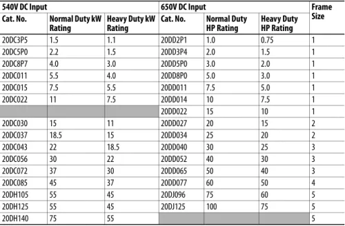
Table 5 - 540/650 Volt DC Input Drives
20DE011 10 7.5 1
20DE017 15 10 1
20DE022 20 15 2
20DE027 25 20 2
20DE032 30 25 3
20DE041 40 30 3
20DE052 50 40 3
20DE062 60 50 4
20DF052 45 37.5 5
20DF060 55 45 5
20DE077 75 60 20DF082 75 55 5
20DE099 100 75 20DF098 90 75 5
20DE125 125 100 20DF119 110 90 6
20DE144 150 125 20DF142 132 110 6
325V DC input Frame
Size Cat. No. Normal Duty
Hp Rating
Heavy Duty Hp Rating
20DB015 5.0 3.0 1
20DB022 7.5 5.0 1
20DB028 10 7.5 2
20DB042 15 10 3
20DB052 20 15 3
20DB070 25 20 4
20DB080 30 25 4
20DN104 40 30 5
20DN130 50 40 5
20DN154 60 50 6
20DN192 75 60 6
20DN260 100 75 6
540V DC Input 650V DC Input Frame
Size Cat. No. Normal Duty kW
Rating
Heavy Duty kW Rating
Cat. No. Normal Duty HP Rating
Heavy Duty HP Rating
20DC3P5 1.5 1.1 20DD2P1 1.0 0.75 1
20DC5P0 2.2 1.5 20DD3P4 2.0 1.5 1
20DC8P7 4.0 3.0 20DD5P0 3.0 2.0 1
20DC011 5.5 4.0 20DD8P0 5.0 3.0 1
20DC015 7.5 5.5 20DD011 7.5 5.0 1
20DC022 11 7.5 20DD014 10 7.5 1
20DD022 15 10 1
20DC030 15 11 20DD027 20 15 2
20DC037 18.5 15 20DD034 25 20 2
20DC043 22 18.5 20DD040 30 25 3
20DC056 30 22 20DD052 40 30 3
20DC072 37 30 20DD065 50 40 3
20DC085 45 37 20DD077 60 50 4
20DH105 55 45 20DJ096 75 60 5
20DH125 55 45 20DJ125 100 75 5
20DH140 75 55 5
600V AC Input 690V AC Input Frame
Size Cat. No. Normal Duty Hp
Rating
Heavy Duty Hp Rating
Cat. No. Normal Duty kW Rating
Heavy duty kW Rating
Table 6 - 810/932 Volt DC Input Drives
CE Conformity
Compliance with the Low Voltage (LV) Directive and Electromagnetic
Compatibility (EMC) Directive has been demonstrated using harmonized
European Norm (EN) standards published in the Official Journal of the
European Communities. PowerFlex drives comply with the EN standards listed
below when installed according to the PowerFlex 700S AC Drives Phase II
Control User and Reference Manuals.
CE Declarations of Conformity are available online at:
http://www.rockwellautomation.com/products/certification/
Low Voltage Directive (2006/95/EC)
•
EN 61800-5-1 Adjustable speed electrical power drive systems –
Part 5-1: Safety requirements – Electrical, thermal and energy.
EMC Directive (2004/108/EC)
•
EN 618003 Adjustable Speed Electrical Power Drive Systems
-Part 3: EMC Product Standard Including Specific Test Methods.
20DH170 90 75 20DJ156 125 100 6
20DH205 110 90 20DJ180 150 125 6
20DH260 132 110 20DJ248 200 150 6
810V DC Input 932V DC Input Frame
Size Cat. No. Normal Duty Hp
Rating
Heavy Duty Hp Rating
Cat. No. Normal Duty kW Rating
Heavy Duty kW Rating
20DE1P7 1.0 0.75 1
20DE2P7 2.0 1.5 1
20DE3P9 3.0 2.0 1
20DE6P1 5.0 3.0 1
20DE9P0 7.5 5.0 1
20DE011 10 7.5 1
20DE017 15 10 1
20DE022 20 15 2
20DE027 25 20 2
20DE032 30 25 3
20DE041 40 30 3
20DE052 50 40 3
20DE062 60 50 4
20DT099 100 75 20DW098 90 75 5
20DT144 150 125 20DW142 132 110 6
540V DC Input 650V DC Input Frame
Size Cat. No. Normal Duty kW
Rating
Heavy Duty kW Rating
Cat. No. Normal Duty HP Rating
Heavy Duty HP Rating
General Considerations
•
If the adhesive label is removed from the top of the drive, the drive must be
installed in an enclosure with side openings less than 12.5 mm (0.5 in.) and
top openings less than 1.0 mm (0.04 in.) to maintain compliance with the
LV Directive.
•
The motor cable should be kept as short as possible to avoid
electromagnetic emission as well as capacitive currents.
•
Use of line filters in ungrounded systems is not recommended.
•
PowerFlex drives may cause radio frequency interference if used in a
residential or domestic environment. The installer is required to take
measures to prevent interference, in addition to the essential requirements
for CE compliance provided in this section, if necessary.
•
Conformity of the drive with CE EMC requirements does not guarantee
an entire machine or installation complies with CE EMC requirements.
Many factors can influence total machine/installation compliance.
•
PowerFlex drives can generate conducted low frequency disturbances
(harmonic emissions) on the AC supply system.
•
More information regarding harmonic emissions can be found in the
PowerFlex 700S AC Drives Phase II Control, Reference Manual,
publication
PFLEX-RM003
.
•
When operated on a public supply system, it is the responsibility of the
installer or user to be sure, by consultation with the distribution network
operator and Rockwell Automation, if necessary, that applicable
requirements have been met.
Essential Requirements for CE Compliance
Conditions 1…6 listed below
must be
satisfied for PowerFlex 700S Phase II
drives to meet the requirements of
EN61800-3
.
1.
Standard PowerFlex 700S CE compatible drive.
2.
Review important precautions/attentions statements throughout this
document before installing drive.
3.
Grounding as described in Grounding Requirements on page
25
.
4.
Output power, control (I/O) and signal wiring must be braided, shield
cable with a coverage of 75% or better, metal conduit or have shielding/
cover with equivalent attenuation.
5.
All shielded cables should terminate with proper shielded connector.
6.
Conditions in
Table 7
below.
Table 7 - PowerFlex 700S EN61800-3 EMC Compatibility (1)
Frames Second Environment First Environment Restricted Distribution
Restrict Motor Cable to 30 m (98 ft) Restrict Motor Cable to 150 m (492 ft)
Any Drive and Option Any Drive and Option External Filter Required
1…6 √ √ √
(1) External filters for First Environment installations and increasing motor cable lengths in Second Environment installations are available. Roxburgh models KMFA (RF3 for UL installations) and MIF or Schaffner FN3258 and FN258 models are recommended.
Common Bus and Precharge Considerations
The following notes must be read and understood. Also refer to Selecting/
Verifying Fan Voltage (Frames 5 and 6 Only) on page
34
through Power Terminal
Blocks on page
41
for additional common bus information.
1.
If drives without internal precharge are used (frames 5 and 6 only), then:
a. precharge capability must be provided in the system to guard against
possible damage, and
b. disconnect switches
Must
Not
be used between the input of the drive
and a common DC bus without the use of an external precharge device.
2.
If drives with internal precharge (frames 1…6) are used with a disconnect
switch to the common bus, then an auxiliary contact on the disconnect
must be connected to a digital input of the drive. The corresponding input
(parameter 361…366) must be set to option 30, “Precharge Enable.” This
provides the proper precharge interlock, guarding against possible damage
to the drive when connected to a common DC bus.
Refer to PowerFlex AC Drives in Common Bus Configurations, publication
DRIVES-AT002
, for more information.
Operating Conditions and Temperatures
PowerFlex 700S frame 1…6 drives are designed to operate at 0…40 °C (32…104
°F) ambient. To operate most frame 1…4 drives in installations between 41 and
50
°
C (105.8 and 122 °F), you must remove the top adhesive label from the
drive. Frames 5 and 6 do not have an adhesive label. See
Table 8
and
Figure 1
on
page
15
below for more information.
Table 8 - Enclosure Types and Acceptable Surrounding Air Temperature
IMPORTANT
Removing the adhesive label from the top of frame 1…4 drives changes the
NEMA/UL enclosure rating from Type 1 to Type Open.
Enclosure Type Temperature Rating Drive
IP20, NEMA/UL Type 1 (with Top Label) (1)
(1) Frames 5 and 6 do not have a label.
0…40 °C (32…104 °F) Frame 1…4, All Ratings 0…50 °C (32…122 °F) Frames 5 and 6, Most Ratings (3)
(3) Refer to the Fusing and Circuit Breakers tables on page 44, for exceptions.
IP20, NEMA/UL Type Open (Top Label Removed) (1)
0…50 °C (32…122 °F) Most Ratings (2) 0…45 °C (32…113 °F) 20DC072 and 20DE062 Only IP00, NEMA/UL Type Open
(Top Label and Vent Plate Removed) (2)
(2) To remove the vent plate, lift the top edge of the plate away from the chassis and rotate the plate out from the back plate. Refer to
Figure 3 on page 17 for location of vent plate.
0…50 °C (32…122 °F) 20DC072 Only Flange Mount
Front (Inside Encl.) - IP00, NEMA/UL Type Open Back/Heat Sink - IP54, NEMA/UL
Type 12
0…55 °C (32…131 °F) 0…40 °C (32…104 °F)
Frames 5 and 6
Minimum Mounting Clearances
Specified vertical clearance requirements are intended to be from the drive to the
closest object that can restrict airflow through the drive heat sink and chassis. The
drive must be mounted in a vertical orientation as shown, and must make full
contact with the mounting surface. Do not use standoffs or spacers. In addition,
inlet air temperature must not exceed the product specification. See
Table 8
on
page
14
for ambient air temperature limits.
Figure 1 - Minimum Mounting Clearance Requirements
IMPORTANT
PowerFlex 700S drives must be mounted in a clean, dry location. Contaminants
such as oils, corrosive vapors and abrasive debris must be kept out of the
enclosure. These enclosures are intended for indoor use primarily to provide a
degree of protection against contact with enclosed equipment. These
enclosures offer no protection against airborne contaminants.
50.8 mm
(2.0 in.)
101.6 mm (4.0 in.)
101.6 mm (4.0 in.)
101.6 mm (4.0 in.)
101.6 mm (4.0 in.)
101.6 mm (4.0 in.)
101.6 mm (4.0 in.)
With Adhesive Label RemovedAdhesive Label With Adhesive Label
Left in Place
Air flow through the drive must not be impeded.
Approximate Dimensions
Figure 2 - Frames 1…3
Dimensions are in millimeters and (inches) A
AA
D 15.0
(0.59)
5.5 (0.22) 5.8
(0.23) dia.
B E
8.0 (0.31)
312 (12.28)
C
Frame 1 Shown
Frame(1)
(1) Refer to Drive Rating to Frame Size Cross References on page 10 for frame information.
Slim Cassette A
Expanded Cassette AA
B C D E
1 135.0 (5.31) 166.9 (6.57) 336.0 (13.23) 200.0 (7.87) 105.0 (4.13) 320.0 (12.60) 2 222.0 (8.74) 253.9 (9.99) 342.5 (13.48) 200.0 (7.87) 192.0 (7.56) 320.0 (12.60) 3 222.0 (8.74) 253.9 (9.99) 517.5 (20.37) 200.0 (7.87) 192.0 (7.56) 500.0 (19.69)
Figure 3 - Bottom Views, Frames 1…3
39.3 (1.55) 57.2 (2.25)
72.7 (2.86) 106.0 (4.17)
139.4 (5.49) 177.4 (6.98) 167.5 (6.59) 156.9 (6.18)
150.9 (5.94)
184.8 (7.28) 157.5
(6.20)
112.1 (4.41) 22.4 (0.88) Dia.
2 Places
28.7 (1.13) Dia.
3 Places
133.3
(5.25) 187.6 (7.39) 25.5 (1.00)
70.0 (2.76) 43.0 (1.69)
96.0 (3.78) 75.9 (2.99)
108.5 (4.27) 67.5 (2.66) 47.5 (1.87)
87.5 (3.44)
22.2 (0.87) Dia.
3 Places 28.6 (1.13) Dia.
185.1 (7.29) 162.3
(6.39)
66.0 (2.60) 94.7 (3.73) 105.3 (4.15)
97.0 (3.82) 137.2 (5.40)
187.0 (7.36) 22.7 (0.89)
29.0 (1.14) 127.7 (5.03) 151.1 (5.95)
160.1 (6.30) 165.1
(6.50)
184.5 (7.26) 22.2 (0.87) Dia.
28.7 (1.13) Dia. 2 Places
37.3 (1.47) Dia. 2 Places
66.0 (2.60) 94.7 (3.73) 105.3 (4.15)
130.0 (5.12) 186.0 (7.32) 22.7 (0.89)
29.0 (1.14) 127.7 (5.03)
160.1 (6.30) 165.1
(6.50)
184.5 (7.26) 28.7 (1.13) Dia.
2 Places
46.7 (1.84) Dia. 2 Places 34.9 (1.37) Dia. 2 Places
Vent Plate
Frame 1 Frame 2
Frame 3 - All Drives, except 50 Hp, 480V (37 kW, 400V) Frame 3 - 50 Hp, 480V (37 kW, 400V) Normal Duty
Figure 4 - Frame 4
C
E
8.0 (0.31)
B
7.0 (0.28)
3 Places A
D 13.0 (0.55)
Lifting Holes 4 Places
7.0 (0.28) 2 Places 15.1 (0.59)
S
AA
312 (12.28)
54.1 (2.13) Dia. 2 Places 47.0 (1.85) Dia. 2 Places 28.7 (1.13) Dia. 2 Places
26.8 (1.06)
36.8 (1.45) 50.7 (2.00) 141.9 (5.59)
105.1 (4.14) 157.9 (6.21) 177.9 (7.00) 189.7 (7.47)
22.2 (0.87) Dia.
63.8 (2.51) 112.0 (4.41)
180.0 (7.09) 65.3 (2.57) 76.0 (2.99)
Dimensions are in millimeters and (inches)
Bottom View
Frame(1)
(1) Refer to Drive Rating to Frame Size Cross References on page 10 for frame information.
Slim Cassette A (Max)
Expanded Cassette AA
B C (Max) D E
Figure 5 - Frame 5, 75 Hp, 480V (55kW, 400V)
Bottom View
HOT surfaces can cause severe burns CAUTION
E
12.5 (0.49)
6.5 (0.26)
B
D A
259.1 (10.20)
Detail
15.0 (0.59) 6.5 (0.26)
37.6 (1.48)
C
Lifting Holes - 4 Places
12.7 (0.50) Dia.
312
(12.28)
S
AA
96.0 (3.78) 159.5 (6.28) 184.0 (7.24) 220.0 (8.66) 229.5 (9.04) 241.9 (9.52)
45.0 (1.77) 85.0 (3.35)
93.2 (3.67) 104.0 (4.09)
150.0 (5.91) 215.0 (8.46)
255.0 (10.04) 28.0 (1.10)
22.2 (0.87) Dia. 2 Places
62.7 (2.47) Dia. 2 Places
34.9 (1.37) Dia. 2 Places
Dimensions are in millimeters and (inches)
Frame(1)
(1) Refer to Drive Rating to Frame Size Cross References on page 10 for frame information.
Slim Cassette A (Max)
Expanded Cassette AA
B C (Max) D E
Figure 6 - Frame 5, 100 Hp, 480V (55kW, 400V)
D A 259.1 (10.20)
Detail
15.0 (0.6) 6.5 (0.3)
37.6 (1.48)
AA
20.5 (0.8)
E B
625.0 (24.6)
12.0 (0.5)
4 x Ø 12.7 (0.5)
617.0 (24.3)
C
13.0 (0.5) 27.6 (1.1) 13.0
(0.5)
Bottom View
96.0 (3.78) 153.5 (6.04) 184.3
(7.26) 188.5 (7.42) 223.5 (8.80) 241.9 (9.52)
44.0 (1.73) 66.4 (2.61)
31.9 (1.26) 42.6 (1.68)
128.0 (5.04) 232.3 (9.15) 28.0 (1.10)
22.2 (0.87) Dia. 2 Places
62.7 (2.47) Dia. 2 Places
Removable Junction Box
34.9 (1.37) Dia.
Dimensions are in millimeters and (inches)
Frame(1)
(1) Refer to Drive Rating to Frame Size Cross References on page 10 for frame information.
Slim Cassette A (Max)
Expanded Cassette AA
B C (Max) D E
Figure 7 - Frame 6
116.6 (4.59) 148.5 (5.85) 222.3
(8.75) 242.0
(9.53) 219.0(8.62)
185.4 (7.30) 151.8 (5.98)
52.1 (2.05) 69.1 (2.72)
130.1 (5.12)
280.1 (11.03)
330.1 (13.00) 230.1 (9.06)
47.1 (1.85) 45.6 (1.80) 56.2 (2.21)
Removable Junction Box 22.2 (0.87) Dia. 4 Places 62.7 (2.47) Dia.
3 Places
34.9 (1.37) Dia.
3 Places
E
13.5 (0.53) 126.3
(4.97)
8.5 (0.33) B
Lifting Holes 4 Places 12.7 (0.50) Dia.
D C
A
360.6 (14.20)
Detail
18.0 (0.71) 8.5 (0.33)
49.6 (1.95)
Detail Old Style Junction Box
New Style Junction Box
Dimensions are in millimeters and (inches)
Frame(1)
(1) Refer to Drive Rating to Frame Size Cross References on page 10 for frame information.
Slim Cassette A (Max)
Expanded Cassette AA
B (2)
(2) Junction Box can be removed if drive is mounted in a cabinet.
C (Max) D E
Step 3: Lift and Mount the
Drive
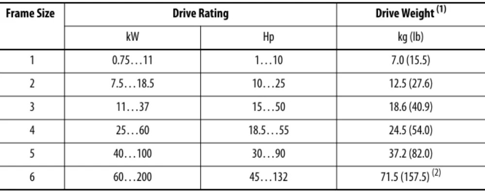
Drive Weights
Table 9 - Approximate Drive Weights
Attaching the Lifting Hardware
All lifting equipment and lifting components (hooks, bolts, lifts, slings, chains,
and so forth) must be properly sized and rated to safely lift and hold the weight of
the drive while mounting. See
Figure 8
and
Figure 9
on page
23
, and
Figure 10
on
page
24
for lifting instructions.
Frame Size Drive Rating Drive Weight (1)
(1) Weights include HIM, DriveLogix controller with ControlNet daughtercard, Hi-Resolution Encoder Option, and 20-COMM-C ControlNet adapter.
kW Hp kg (lb)
1 0.75…11 1…10 7.0 (15.5)
2 7.5…18.5 10…25 12.5 (27.6)
3 11…37 15…50 18.6 (40.9)
4 25…60 18.5…55 24.5 (54.0)
5 40…100 30…90 37.2 (82.0)
6 60…200 45…132 71.5 (157.5) (2)
(2) Add an additional 3.6 kg (8.0 lb) for 200 Hp drives.
ATTENTION:
To guard against possible personal injury and/or equipment
damage…
•
Inspect all lifting hardware for proper attachment before lifting drive.
•
Do not allow any part of the drive or lifting mechanism to make contact with
electrically charged conductors or components.
•
Do not subject the drive to high rates of acceleration or deceleration while
transporting to the mounting location or when lifting.
•
Do not allow personnel or their limbs directly underneath the drive when it is
being lifted and mounted.
Figure 8 - Lifting Frame 4 Drives
Figure 9 - Lifting Frame 5 Drives S
>1/2 A
A
< 45°
S
>1/2 A
A
Figure 10 - Lifting Frame 6 Drives
>1/2 A
A
Step 4: Power Wiring
Grounding Requirements
The drive Safety Ground-PE must be connected to system ground. Ground
impedance must conform to the requirements of national and local industrial
safety regulations and/or electrical codes. The integrity of all ground connections
should be periodically checked.
Figure 11 - Typical Grounding
Shield Termination - SHLD
The Shield terminal (see page
39
) provides a grounding point for the motor cable
shield. It must be connected to an earth ground by a separate continuous lead.
The motor cable shield should be connected to this terminal on the drive and the
motor frame. Use a shield terminating or EMI clamp to connect shield to this
terminal.
ATTENTION:
National Codes and standards (NEC, VDE, BSI and so forth) and
local codes outline provisions for safely installing electrical equipment.
Installation must comply with specifications regarding wire types, conductor
sizes, branch circuit protection and disconnect devices. Failure to do so may
result in personal injury and/or equipment damage.
U (T1) V (T2)
W (T3)
R (L1) S (L2)
T (L3)
PE
Unbalanced, Ungrounded or Resistive Grounded Distribution
Systems
If phase to ground voltage will exceed 125% of normal or the supply system is
ungrounded, refer to Wiring and Grounding Guidelines for Pulse Width
Modulated (PWM) AC Drives, publication
DRIVES-IN001
, for more
information.
RFI Filter Ground
Using an optional RFI filter may result in relatively high ground leakage currents.
Therefore, the filter must only be used in installations with grounded AC supply
systems and be permanently installed and solidly grounded (bonded) to the
building power distribution ground. Be sure that the incoming supply neutral is
solidly connected (bonded) to the same building power distribution ground.
Grounding must not rely on flexible cables and should not include any form of
plug or socket that would permit inadvertent disconnection. Some local codes
may require redundant ground connections. The integrity of all connections
should be periodically checked. Refer to the instructions supplied with the filter.
ATTENTION:
PowerFlex 700S drives contain protective MOVs and common
mode capacitors that are referenced to ground. These devices must be
configured according to the recommendations in
Table 10
on page
27
.
Power Jumpers
PowerFlex 700S Phase II drives contain protective MOVs and Common Mode
Capacitors that are referenced to ground (see below). To guard against unstable
operation and/or damage, the drive must be properly configured as shown in
Table 10
on page
27
.
Table 10 - Recommended Power Jumper Configurations
IMPORTANT
All PowerFlex 700S Phase II drives are shipped with the DC bus common mode
capacitors referenced to ground. The following installation instructions must
be completed before applying power to the drive.
Power Source Type (1)
(1) It is highly recommended to accurately determine the power source type and then configure appropriately.
MOV/Input Filter Caps (2)
(2) When MOVs are disconnected, the power system must have its own transient protection to verify known and controlled voltages.
DC Bus Common Mode Caps
Benefits Of Correct Configuration on Power Source Type
Solid Ground
• AC fed, solidly grounded
• DC fed from passive rectifier, which has an AC source and solid ground
Connected Connected • UL compliance,
• Reduced electrical noise,
• Most stable operation,
• EMC compliance,
• Reduced voltage stress on components and motor bearings
Non-Solid Ground • AC fed ungrounded
• Impedance grounded
• High resistive ground
• B phase ground
• Regenerative unit such as common DC bus supply & brake
• DC fed from an active converter
Disconnected Disconnected • Helps avoid severe equipment
damage when ground fault occurs
R/L1 S/L2 T/L3
DC+ DC–
MOV and AC EMI Capacitor Phase to Ground
Common Mode Capacitor Phase to Ground
Jumper Wire Jumper Wire
To connect or disconnect these devices, refer to pages 29 through 32.
In addition, on an ungrounded distribution system where the line-to-ground
voltages on any phase could exceed 125% of the nominal line-to-line voltage, an
isolation transformer should be installed. See Wiring and Grounding Guidelines
for PWM AC Drives, publication
DRIVES-IN001
for more information on
impedance grounded and ungrounded systems.
Jumper Installation, Removal and Storage
PowerFlex 700S drives utilize plug-in style jumpers and jumper wires. Most drives
will have a jumper storage area inside the front cover. Extra jumpers or jumpers
that have been removed should be stored in this location for use at a later time.
Insulating Jumper Wires
Some drives utilize nylon screws and spacers to insulate jumper
wires from ground and secure them to the chassis. The
components must be installed as shown.
Drive Identification
Refer to the drive nameplate and locate the “Voltage Code,” “Current Rating,”
“Frame,” and “Series”. Use this information to locate the proper procedure in the
following tables.
IMPORTANT
Common mode capacitors are required to conform with the EMC directive.
Removing these devices will withdraw the associated directive.
Cat No. 20D D xxx x x xxxxxxx
Made in the USA (TAC 1J)
Rockwell Automation, Mequon WI 53092-4400
UL TYPE 1/IP20
Mfd. in 2007 on Aug 1 Frame: 3
Serial Number: xxxxxxx
Series: B
Original Firmware V. x.xxx
Listed Ind. Cont Eq. 966X
U
c
®L
USNormal Duty Power
Heavy Duty Power
AC Voltage Range
Amps
Input: 3 Phase, 47-63Hz
Output: 3 Phase, 0-400 Hz
AC Voltage Range
Base Hz (default)
Continuous Amps
1 Min Overload Amps
3 Sec Overload Amps
xxx kW xxx kW
342-440
xxx 0-400 50 Hz xxx xxx xxx
xxx kW xxx kW
432-528
xxx
400V 480V
0-460 60 Hz xxx xxx
xxx N223
Voltage Code
Frame
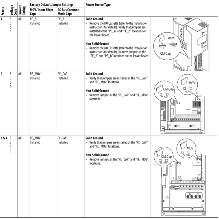
Table 11 - Jumper Settings and Locations Fr am e Vo lt ag e Co de
Current Rati
ng
Factory Default Jumper Settings Power Source Type MOV/Input Filter
Caps
DC Bus Common Mode Caps 1 B C D E All PE_B Installed PE_A Installed Solid Ground
• Remove the I/O Cassette (refer to the Installation Instructions for details). Verify that jumpers are installed at the “PE_A” and “PE_B” locations on the Power Board.
Non-Solid Ground
• Remove the I/O Cassette (refer to the Installation Instructions for details). Remove jumpers at the “PE_A” and “PE_B” locations on the Power Board.
2 B C D E All PE_MOV Installed PE_CAP Installed Solid Ground
• Verify that jumpers are installed at the “PE_CAP” and “PE_MOV” locations.
Non-Solid Ground
• Remove jumpers at the “PE_CAP” and “PE_MOV” locations.
3 & 4 B C D E All PE_MOV Installed PE-CAP Installed Solid Ground
• Verify that jumpers are installed at the “PE_CAP” and “PE_MOV” locations.
Non-Solid Ground
• Remove jumpers at the “PE_CAP” and “PE_MOV” locations. BR1 BR2 DC+ DC– PE U/T1 V/T2 W/T3 R/L1 S/L2 T/L3 Use 75C Wire Only #10-#14 A WG Torque to 7 in-l b s !DANGER
PE A PE B
CM Cap MOV
BR1 BR2 DC+ DC- U/T1 V/T2 W/T3
SHLD SHLD
PE R/L1 S/L2 T/L3
PE 2 MOV-PE JMPR
PE 1
AUX IN+ AUX OUT–
75C Cu Wire 6 AWG [10MM2] Max. 12 IN. LBS. 1.4 N-M} TORQUE
WIRE STRIP CONTR OL PO WER
PE 4 PE 3
MOV
PE_MOV
CM Cap
PE_CAP
BR1 BR2 DC+ DC- U/T1 V/T2 W/T3R/L1 S/L2 T/L3 PE MOV PE CAP
75C Cu Wire
3 AWG [25MM2] Max. 16 IN. LBS. 1.8 N-M} TORQUE
WIRE STRIP CONTR OL PO WER AUX IN + – SHLD SHLD PE
75C Cu Wire 6 AWG [10MM2] Max.
BR1 BR2
12 IN. LBS. 1.4 N-M} TORQUE
PE_CAP
PE_MOV
CM Cap
Fram e Vo lt ag e
Code Current Rati
ng
Factory Default Jumper Settings Power Source Type MOV/Input Filter
Caps(1) (2)
DC Bus Common Mode Caps 5 C F W 052 060 140 Two green/yellow wires connected to the Power Terminal Block rail
Green/yellow wire to CM Cap Board is connected to ground
Solid Ground
1. CM Cap jumper wire should be connected to ground with a metal screw. Verify. If necessary, remove the nylon screw/spacer and insert a metal M5 x 8 screw. Torque to 3.2 N•m (28 lb•in).
2. MOV/Input Filter Cap jumper wires should be connected to ground with a metal screw. Verify. If necessary, remove the nylon screw/spacer and insert a metal M5 x 12 screw.
Non-Solid Ground
1. CM Cap jumper wire should be insulated from ground with a nylon screw/spacer. Verify. If necessary, remove the metal screw and insert a M5 x 15 nylon screw/spacer.
2. MOV/Input Filter Cap jumper wires should be insulated from ground with a nylon screw/spacer. Verify. If necessary, remove the metal screw and insert a
M5 x 20 nylon screw/spacer.
E F T W 077 082 098 099 Two green/yellow wires connected to chassis ground
Green/yellow wire to CM Cap Board is connected to ground
Solid Ground
1. CM Cap jumper wire should be connected to ground with a metal screw. Verify. If necessary, remove the nylon screw/spacer and insert a metal M5 x 8 screw. Torque to 3.2 N•m (28 lb•in).
2. MOV jumper wire should be connected to ground with metal screws. Verify. If necessary, remove the nylon screw/spacers and insert metal M5 x 12 screws. 3. Input Filter Cap jumper wire should be connected to
ground with a metal screw. Verify. If necessary, remove the nylon screw/spacer and insert metal M5 x 8 screw.
Non-Solid Ground
1. CM Cap jumper wire should be insulated from ground with a nylon screw/spacer. Verify. If necessary, remove the metal screw and insert a M5 x 15 nylon screw/spacer.
2. MOV jumper wire should be insulated from ground with a nylon screw/spacer. Verify. If necessary, remove the metal screws and insert a M5 x 20 nylon screw/spacer.
3. Input Filter Cap jumper wire should be insulated from ground with a nylon screw/spacer. Verify. If necessary, remove the metal screws and insert a M5 x 15 nylon screw/spacer.
(1) AC input drives only. MOV’s and input filter caps do not exist on DC input drives. (2) When removing MOV’s, the input filter capacitor must also be removed.
WIRE RANGE: 14-1/0 AWG (2.5-35 MM2) TORQUE: 32 IN-LB (3.6 N-M) STRIP LENGTH: 0.67 IN (17 MM) USE 75 C CU WIRE ONLY POWER TERMINAL RATINGS
WIRE RANGE: 6-1/0 AWG (16-35 MM2) TORQUE: 44 IN-LB (5 N-M) STRIP LENGTH: 0.83 IN (21 MM) GROUND TERMINAL RATINGS (PE)
300 VDC EXT PWR SPLY TERM (PS+, PS-) WIRE RANGE: 22-10 AWG (0.5-4 MM2) TORQUE: 5.3 IN-LB (0.6 N-M) STRIP LENGTH: 0.35 IN (9 MM) 17
21
INPUT AC OUTPUT
Optional Communications
Module
9
CM Cap MOV
MOV / Input Filter Cap
WIRE RANGE: 14-1/0 AWG (2.5-35 MM2) TORQUE: 32 IN-LB (3.6 N-M) STRIP LENGTH: 0.67 IN (17 MM) USE 75 C CU WIRE ONLY POWER TERMINAL RATINGS
WIRE RANGE: 6-1/0 AWG (16-35 MM2) TORQUE: 44 IN-LB (5 N-M) STRIP LENGTH: 0.83 IN (21 MM) GROUND TERMINAL RATINGS (PE)
300 VDC EXT PWR SPLY TERM (PS+, PS-) WIRE RANGE: 22-10 AWG (0.5-4 MM2) TORQUE: 5.3 IN-LB (0.6 N-M) STRIP LENGTH: 0.35 IN (9 MM) 17
21
INPUT AC OUTPUT
Optional Communications
Module 9 PE CM Cap MOV MOV Input Filter Cap
Fr
am
e
Vo
lt
ag
e
Co
de
Current Rati
ng
Factory Default Jumper Settings Power Source Type MOV/Input Filter
Caps(1) (2)
DC Bus Common Mode Caps 5 B
C D H J N P R
All, except C140 (see next page)
Two green/yellow wires connected to the Power Terminal Block rail
Green/yellow wire is connected to ground
Solid Ground
1. CM Cap jumper wire should be connected to ground with a metal screw. Verify.
• Newer Drives - If necessary, remove the nylon screw/spacer and insert a metal M5 x 8 screw. Torque to 3.2 N•m (28 lb•in).
• Older Drives - Remove the I/O Cassette (see Installation Instructions for details). The green/ yellow CM Cap jumper wire is located on the back of chassis and should be connected to ground with a metal screw. If necessary, remove the insulation from the wire terminal and connect to chassis with a metal M5 x 12 screw. Torque screw to 3.2 N•m (28 lb•in). 2. MOV/Input Filter Cap jumper wires should be
connected to ground with a metal screw. Verify. If necessary, remove the nylon screw/spacer and insert a metal M5 x 12 screw.
Non-Solid Ground
1. CM Cap jumper wire should be insulated from ground. Verify.
• Newer Drives - If necessary, remove the metal screw and insert a M5 x 15 nylon screw/spacer.
• Older Drives - Remove the I/O Cassette (see Installation Instructions for details). If necessary, insulate/secure jumper wire to guard against unintentional contact with chassis or components.
2. MOV/Input Filter Cap jumper wires should be insulated from ground with a nylon screw/spacer. Verify. If necessary, remove the metal screw and insert a M5 x 20 nylon screw/spacer.
(1) AC input drives only. MOV’s and input filter caps do not exist on DC input drives. (2) When removing MOV’s, the input filter capacitor must also be removed.
WIRE RANGE: 14-1/0 AWG (2.5-35 MM2) TORQUE: 32 IN-LB (3.6 N-M) STRIP LENGTH: 0.67 IN (17 MM) USE 75 C CU WIRE ONLY POWER TERMINAL RATINGS
WIRE RANGE: 6-1/0 AWG (16-35 MM2) TORQUE: 44 IN-LB (5 N-M) STRIP LENGTH: 0.83 IN (21 MM) GROUND TERMINAL RATINGS (PE)
300 VDC EXT PWR SPLY TERM (PS+, PS-) WIRE RANGE: 22-10 AWG (0.5-4 MM2) TORQUE: 5.3 IN-LB (0.6 N-M) STRIP LENGTH: 0.35 IN (9 MM) 17
21
INPUT AC OUTPUT
Optional Communications
Module
9
CM Cap - Older Drives
MOV / Input Filter Cap MOV
Fr am e Vo lt ag e Co de
Current Rati
ng
Factory Default Jumper Settings Power Source Type MOV/Input Filter
Caps(1) (2)
DC Bus Common Mode Caps 6 B C D H J N P R
All Two green/yellow wires connected to Power Terminal Block “PE”
Green/yellow wire to CM Cap Board is connected to Power Terminal Block “PE”
Solid Ground
1. The green/yellow CM Cap jumper wire should be connected to “PE.”
2. The MOV/Input Filter Cap jumper wires should be connected to “PE.”
Non-Solid Ground
1. The green/yellow CM Cap jumper wire should be insulated from ground. If necessary, remove the jumper wire from “PE” and insulate/secure it to guard against unintentional contact with chassis or components. Important: Do Not Remove/Disconnect the larger green/ yellow wire.
2. MOV/Input Filter Cap jumper wires should be insulated from ground. If necessary, remove the jumper wires from “PE” and individually insulate/ secure each jumper wire to guard against unintentional contact with chassis or components.
E F T W
All Two green/yellow wires connected to Power Terminal Block “PE” and chassis
Green/yellow wire to CM Cap Board is connected to Power Terminal Block “PE”
Solid Ground
1. The green/yellow CM Cap and MOV jumper wires should be connected to “PE.” 2. The Input Filter Cap jumper wire (top right)
should be connected to chassis ground with a metal screw. Verify. If necessary, remove the nylon screw/spacer and insert a metal M5 x 10 screw. Torque to 3.2 N•m (28 lb•in).
Non-Solid Ground
1. The green/yellow CM Cap and MOV jumper wires should be insulated from ground. If necessary, remove them from “PE” and individually insulate/secure each jumper wire to guard against unintentional contact with chassis or components. Important: Do Not Remove/Disconnect the larger green/ yellow wire.
2. The Input Filter Cap jumper wire (top right) should be insulated from ground with a nylon screw/spacer. Verify. If necessary, remove the metal screw and insert a M5 x 15 nylon screw/ spacer.
(1) AC input drives only. MOV’s and input filter caps do not exist on DC input drives. (2) When removing MOV’s, the input filter capacitor must also be removed.
DC– DC+ BR1 BR2
USE 75 C COPPER WIRE ONLY, TORQUE 52 IN-LB (6 N-M)
22-10 AWG 5.3 IN-LB (0.6 N-M)
WIRE STRIP
PS+PS–
USE 75 C COPPER WIRE ONLY TORQUE 52 IN-LB (6 N-M) U T1 V T2 W T3 R L1 S L2 INPUT OUTPUT T L3 PE PE
Optional Communications
Module
PE PE
MOV Input Filter Cap CM Cap DO NOT REMOVE MOV DC– DC+ BR1 BR2
USE 75 C COPPER WIRE ONLY, TORQUE 52 IN-LB (6 N-M)
22-10 AWG 5.3 IN-LB (0.6 N-M)
WIRE STRIP
PS+PS–
USE 75 C COPPER WIRE ONLY TORQUE 52 IN-LB (6 N-M) U T1 V T2 W T3 R L1 S L2 INPUT OUTPUT T L3 PE PE
Optional Communications
Module
Input Filter Cap
PE PE
MOV CM Cap DO NOT REMOVE
AC Supply Source Considerations
PowerFlex drives are suitable for use on a circuit capable of delivering up to a
maximum of 200,000 rms symmetrical amperes, 600 volts with recommended s/
circuit breakers.
If a residual current detector (RCD) is used as a system ground fault monitor,
only Type B (adjustable) devices should be used to avoid nuisance tripping.
Input Power Conditioning
Certain events on the power system supplying a drive can cause component
damage or shortened product life. These conditions are divided into two basic
categories:
1. All Drives
•
The power system has power factor correction capacitors switched in
and out of the system, either by the user or by the power company.
•
The power source has intermittent voltage spikes in excess of 6000
volts. These spikes could be caused by other equipment on the line or by
events such as lightning strikes.
•
The power source has frequent interruptions.
2. 5 Hp or Less Drives (in addition to “1” above)
•
The nearest supply transformer is larger than 100 kVA or the available
short circuit (fault) current is greater than 100,000 A.
•
The impedance in front of the drive is less than 0.5%.
If any or all of these conditions exist, it is recommended that the user install a
minimum amount of impedance between the drive and the source. This
impedance could come from the supply transformer itself, the cable between the
transformer and drive or an additional transformer or reactor. The impedance
can be calculated using the information supplied in Wiring and Grounding
Guidelines for Pulse Width Modulated (PWM) AC Drives, publication
DRIVES-IN001
.
Single-Phase Input Power
The PowerFlex 700S drive is typically used with a three-phase input supply.
Single-phase operation of the drive is not currently rated under the UL508C
listing. Rockwell Automation has verified that single-phase operation with
output current derated by 50% of the three-phase ratings identified in the Fusing
and Circuit Breakers tables on page
44
will meet all safety requirements.
ATTENTION:
To guard against personal injury and/or equipment damage
caused by improper fusing or circuit breaker selection, use only the
recommended line s/circuit breakers specified in Fusing and Circuit Breakers on
page
44
.
AC Input Phase Selection (Frames 5 and 6 Only)
Moving the “Line Type” jumper shown in
Figure 12
on page
35
will select single
or three-phase operation. Remove plastic guard to access jumper.
Selecting/Verifying Fan Voltage (Frames 5 and 6 Only)
Frames 5 and 6 utilize a transformer to match the input line voltage to the
internal fan voltage. If your line voltage is different than the voltage class specified
on the drive nameplate, it may be necessary to change transformer taps as shown
below. Common bus (DC input) drives require user supplied 120 or 240V AC to
power the cooling fans. The power source is connected between “0 VAC” and the
terminal corresponding to your source voltage (see
Figure 12
on page
35
).
ATTENTION:
To avoid a shock hazard, be sure that all power to the drive has
been removed before performing the following.
IMPORTANT
When selecting single-phase operation, input power must be applied to the R
(L1) and S (L2) terminals only.
ATTENTION:
To avoid a shock hazard, be sure that all power to the drive has
Fan VA Rating (DC Input Drives Only)
Figure 12 - Phase Selection Jumper and Fan Transformer Locations (Frame 5 shown)
Frame 5 and 6 Transformer Tap Access
The transformer is located behind the power terminal block in the area shown in
Figure 12
. Access is gained by releasing the terminal block from the rail. To
release terminal block and change tap:
1.
Locate the small metal tab at the bottom of the end block.
2.
Press the tab in and pull the top of the block out. Repeat for next block if
desired.
3.
Select appropriate transformer tap.
4.
Replace block(s) in reverse order.
Frame Fan Voltage (120V or 240V)
5 100 VA
6 138 VA
WIRE RANGE: 14-1/0 AWG (2.5-35 MM2) TORQUE: 32 IN-LB (3.6 N-M) STRIP LENGTH: 0.67 IN (17 MM) USE 75 C CU WIRE ONLY POWER TERMINAL RATINGS
WIRE RANGE: 6-1/0 AWG (16-35 MM2) TORQUE: 44 IN-LB (5 N-M) STRIP LENGTH: 0.83 IN (21 MM) GROUND TERMINAL RATINGS (PE)
300 VDC EXT PWR SPLY TERM (PS+, PS-) WIRE RANGE: 22-10 AWG (0.5-4 MM2) TORQUE: 5.3 IN-LB (0.6 N-M) STRIP LENGTH: 0.35 IN (9 MM) 17
21
INPUT AC OUTPUT
Optional Communications
Module
9
480 Volt Tap 600 Volt Tap 690 Volt Tap
400 Volt Tap
400 Volt or 600 Volt Tap 480V or 690 Volt Tap
LINE TYPE SPARE 1 SPARE 2
3-PH 1-PH
Line Type Jumper
Fan Voltage Selection (Frame 5 shown)
Important Common Bus (DC Input) Application Notes
1.
If drives without internal precharge are used (Frames 5 and 6 only), then:
•
precharge capability must be provided in the system to guard against
possible damage, and
•
disconnect switches Must Not be used between the input of the drive
and a common DC bus without the use of an external precharge device.
2.
If drives with internal precharge (Frames 1…6) are used with a disconnect
switch to the common bus, then an auxiliary contact on the disconnect
must be connected to a digital input of the drive. The corresponding input
(parameters 825…830) must be set to “Precharge Enable”. This provides
the proper precharge interlock, guarding against possible damage to the
drive when connected to a common DC bus.
Auxiliary Control Power Supply
An auxiliary power supply can be used to keep the 700S control assembly
energized when input power is de-energized. This allows the main control board,
DriveLogix controller and any feedback option cards to continue operation.
Refer to Power Terminal Block Specifications on page
39
for connection
information. You must set bit 17 “Aux Pwr Sply” of Par 153 [Control Options] to
enable this feature. Refer to the PowerFlex 700S Auxiliary Control Power Supply
(20-24V-AUX1), Installation Instructions, publication
20D-IN021
, for more
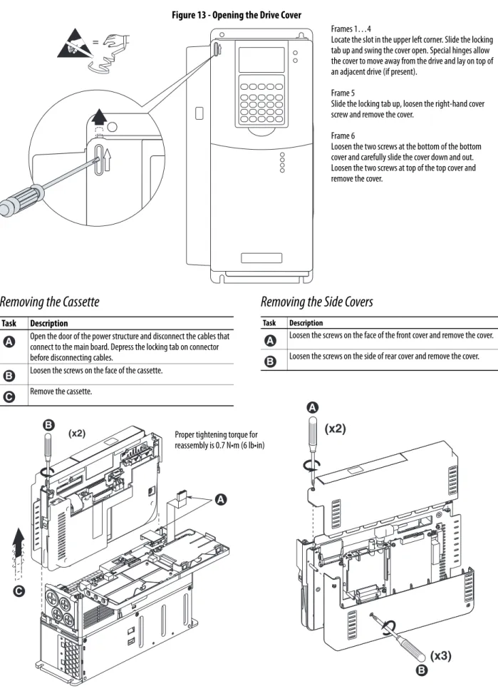
Accessing the Terminals
Figure 13 - Opening the Drive Cover
(x2)
(x3)
=
BR1 BR2 DC+ DC-PE U/T1 V/T2 W/T3 R/L1 L2
(x2) Proper tightening torque for
reassembly is 0.7 N•m (6 lb•in)
Removing the Cassette
Task Description
Open the door of the power structure and disconnect the cables that connect to the main board. Depress the locking tab on connector before disconnecting cables.
Loosen the screws on the face of the cassette. Remove the cassette.
A
B C
Removing the Side Covers
Task DescriptionLoosen the screws on the face of the front cover and remove the cover. Loosen the screws on the side of rear cover and remove the cover.
A B
Frames 1…4
Locate the slot in the upper left corner. Slide the locking tab up and swing the cover open. Special hinges allow the cover to move away from the drive and lay on top of an adjacent drive (if present).
Frame 5
Slide the locking tab up, loosen the right-hand cover screw and remove the cover.
Frame 6
Loosen the two screws at the bottom of the bottom cover and carefully slide the cover down and out. Loosen the two screws at top of the top cover and remove the cover.
A B
C
A
Cable Entry Plate Removal
If additional wiring access is needed, the cable entry plate on frame 1…3 drives
can be removed. Loosen the screws securing the plate to the chassis and slide the
plate down and off the drive.
Power Wiring Access Panel Removal
IMPORTANT
Removing the cable entry plate on frame 1…3 limits the maximum
surrounding air temperature to 40 °C (104 °F).
ATTENTION:
Removing the access panel/cover exposes dangerous voltages on
the terminals and negates the enclosure type rating. Replace the access panel/
cover when service is complete. Failure to comply may result in personal injury
or equipment damage.
Frame Removal Procedure (Replace when wiring is complete)
1, 2 & 6 The access panel is part of the front cover, see Figure 13 on page 37. 3 Open front cover and gently tap/slide the access panel down and out. 4 Loosen the 4 screws and remove the access panel.
5 Remove the front cover (see Figure 13 on page 37) and gently tap/slide the access panel up and out.
SHLD
SHLD
PE
Power Wire Recommendations
Power Terminal Block Specifications
Refer to illustrations on pages
40
and
41
for terminal block locations.
Type Description Min Insulation
Rating Power (1)(2)
(1) Control and signal wires should be separated from power wires by at least 0.3 meters (1 foot). (2) The use of shielded wire for AC input power may not be necessary but is always recommended.
Standard • Four tinned copper conductors with XLPE insulation.
• Copper braid/aluminum foil combination shield and tinned copper drain wire.
• PVC jacket.
600V, 75 °C (167 °F)
No. Name Frame Description Wire Size Range(1) Torque Terminal Bolt Size(2) Maximum Minimum Maximum Recommended
1 Power Terminal Block 1 Input power and motor connections 4.0 mm2 (10 AWG)
0.5 mm2 (22 AWG) 1.7 N•m (15 lb•in) 0.8 N•m (7 lb•in) — 2 Input power and motor connections 10.0 mm2
(6 AWG)
0.8 mm2 (18 AWG) 1.7 N•m (15 lb•in) 1.4 N•m (12 lb•in) — 3 Input power and motor connections 25.0 mm2
(3 AWG)
2.5 mm2 (14 AWG) 3.6 N•m (32 lb•in) 1.8 N•m (16 lb•in) —
BR1, BR2 10.0 mm2
(6 AWG)
0.8 mm2 (18 AWG) 1.7 N•m (15 lb•in) 1.4 N•m (12 lb•in) — 4 Input power and motor connections 35.0 mm2
(1/0 AWG)
10 mm2 (8 AWG) 4.0 N•m (24 lb•in) 4.0 N•m (24 lb•in) — 5
(75 HP)(3)
R, S, T, BR1, BR2, DC+, DC-, U, V and W 50.0 mm2 (1/0 AWG)
2.5 mm2 (14 AWG)
See Note (4) See Note (3) —
PE 50.0 mm2
(1/0 AWG)
4.0 mm2 (12 AWG)
— 5
(100 HP)(3)
R, S, T, DC+, DC-, U, V and W 70.0 mm2 (2/0 AWG)
16.0 mm2 (6 AWG)
—
BR1, BR2 50.0 mm2
(1/0 AWG)
2.5 mm2 (14 AWG)
—
PE 50.0 mm2
(1/0 AWG)
4.0 mm2 (12 AWG)
— 6 Input power and motor connections 120.0 mm2
(4/0 AWG)(5)
2.5 mm2 (14 AWG) 6 N•m (52 lb•in) 6 N•m (52 lb•in) —
2 SHLD Terminal 1-6 Terminating point for wiring shields — — 1.6 N•m
(14 lb•in)
1.6 N•m (14 lb•in)
M12
3 AUX Terminal Block 1-4 Auxiliary Control Voltage(6) PS+,
PS-1.5 mm2 (16 AWG)
0.2 mm2 (24 AWG)
— — —
5-6 4.0 mm2
(10 AWG)
0.5 mm2 (22 AWG) 0.6 N•m (5.3 lb•in) 0.6 N•m (5.3 lb•in) —
4 Fan Terminal Block (Common Bus Only)
5-6 User Supplied Fan Voltage 0V AC, 120V AC, 240V AC
4.0 mm2 (10 AWG)
0.5 mm2 (22 AWG) 0.6 N•m (5.3 lb•in) 0.6 N•m (5.3 lb•in) M10
(1) Maximum/minimum sizes that the terminal block will accept - these are not recommendations.
(2) Apply counter torque to the nut on the other side of terminations when tightening or loosening the terminal bolt to avoid damage to the terminal. (3) Not all terminals present on all drives.
(4) Refer to the terminal block label inside the drive.
(5) If necessary, two wires can be used in parallel to any of these terminals using two lugs.