AARF-HT: Adaptive Auto Rate Fallback for
High-Throughput IEEE 802.11n WLANs
Hery Munanzar
1, Teuku Yuliar Arif
2and Syahrial
31,2,3
Electrical and Computer Engineering Department, Faculty of Engineering, Syiah Kuala University, Indonesia
Abstract: Wireless Local Area Network (WLAN) has been progressing rapidly. The IEEE 802.11n Physical (PHY) layer provides wider channel bandwidth, shorter guard interval, and up to four data streams. Therefore PHY 802.11n has a maximum of 128 data rate options from 6.5 Mbps to 600 Mbps. In addition, Medium Access Control (MAC) has been added Aggregate MAC Protocol Data Unit (AMDPU) scheme. If AMPDU is transmitted with a data rate corresponding to the channel conditions, then the probability AMPDU is received without error becomes increased. MAC determines the data rate used for transmitting AMPDU using a rate adaptation algorithm. Therefore some papers have proposed rate adaptation algorithms based on channel conditions. In this paper we propose a new rate adaptation algorithm that we call Adaptive Auto Rate Fallback for High Throughput (AARF-HT). Our development is done using NS-3 simulator version 3.26. AARF-HT algorithm performance is also tested through a number of simulations extensively. The simulation results show the data rate adaptation function based on the channel width, guard interval and the number of spatial streams in IEEE 802.11n WLAN has functioned well. The test results also show the AARF-HT algorithm resulted in higher throughput compared to the AARF algorithm.
Keywords: Rate Adaptation, AARF, High Throughput, 802.11n, AARF-HT.
1.
Introduction
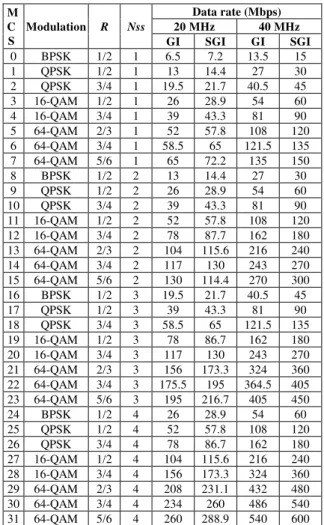
The IEEE 802.11n standard, which is the fourth generation Wireless Local Area Network (WLAN), has developed in Physical (PHY) and Medium Access Control (MAC) layers. Development in PHY is 20/40 MHz channel bandwidth, Guard Interval (GI) 800 ns / Short GI (SGI) 400 ns, and uses Multiply Input Multiple Output (MIMO) 1/2/3/4 spatial streams. If a maximum configuration of 40 MHz channel bandwidth, SGI and 4 spatial stream is used, the WLAN IEEE 802.11n has 128 data rate options, from 6.5 Mbps to 600 Mbps as shown in Table 1. The 802.11n PHY layer is called High Throughput PHY (HT-PHY) [1].
In MAC 802.11n, a more efficient frame format developed using the Aggregate MAC Service Data Unit (AMSDU) scheme and the Aggregate MAC Protocol Data Unit (AMPDU) scheme. The AMSDU scheme is used to improve the efficient use of MAC headers, where multiple MAC Service Data Units (MSDU) with the same destination address are transmitted using only one MAC header as shown in Figure 1. Unlike the AMPDU scheme, it is used to improve the efficiency of PHY layer headers by means of multiple MAC Protocol Data Units (MPDU) that have the same destination address, transmitted using only one PHY header as shown in Figure 2. In addition, MAC 802.11n has used the Enhance Distributed Channel Access (EDCA) access channel method that provides Quality of Service (QoS) functions.
As for the explanation in the IEEE 802.11 standard, MAC determines the data rate used for MPDU transmission using a rate adaptation algorithm. However, the IEEE 802.11 standard does not specify how the rate adaptation algorithm works in determining the data rate used for MPDU transmission. Therefore some papers have proposed rate adaptation algorithms for WLANs to produce optimal throughput according to channel conditions.
Several rate adaptation algorithms based on proposed channel conditions specifically for the high throughput of WLAN IEEE 802.11n are Minstrel-HT [2], RAMAS [3], L3S [4], MiRA [5], CRA [6] and HiWiLA [7]. However, the increase or decrease of data rate in Minstrel-HT, MiRA and CRA is based on random probing method which resulted in the possibility that the selected data rate is not suitable with channel condition. In contrast to RAMAS, L3S, HiWiLA is done based on order probing and produces optimal throughput. However, these three algorithms are only used for adaptation rates up to 2 and 3 spatial streams. Other papers have proposed another approach to increase throughput in WLANs [8]-[9].
In this paper, we propose a new rate adaptation algorithm developed from the Adaptive Auto Rate Fallback (AARF) algorithm [10]. The AARF algorithm increases and decreases the data rate also based on the order probing, however the AARF performs the probing data rate does not consider the channel bandwidth, guard interval and the number of spatial streams which is provided on the IEEE 802.11n WLAN. Therefore in this paper we propose AARF algorithm for High-Throughput (AARF-HT) in order to adapt 802.11n data rate according to the channel condition.
In the AARF-HT algorithm we add channel width, guard interval, spatial stream and maximum number of data rate index attributes. With the addition of these attributes, AARF-HT provides the number of data rate options according to the combination of attribute values used. Each choice of data rate we give the index rate number. These rate index number will be increased or decreased by AARF-HT. We implemented and tested the performance of the AARF-HT algorithm using the NS-3 network simulator [13]. The simulation results show that AARF-HT can adapt the WLAN IEEE 802.11n rate based on channel condition and produce optimal throughput.
2.
Related Works
Based on literature studies, many papers have proposed rate adaptation algorithm. But most of the proposed algorithms are designed for older IEEE 802.11b/a/g WLAN standards. Several recent algorithms have been proposed for rate adaptation in the IEEE 802.11n High Throughput WLAN. In this section we briefly describe each of the proposed rate adaptation algorithms.
2.1Rate adaptation algorithm for legacy IEEE 802.11
Most papers, such as [10]-[12], have proposed a rate adaptation algorithm for older WLAN standards, i.e. IEEE 802.11b/a/g. Paper [11] has proposed Auto Rate Fallback (ARF) algorithm in which rate adaptation is performed on the transmitter side which increases or decreases the data rate in sequence based on the number of MPDU successfully or failed to be delivered constantly. The AARF and Adaptive Multi-Rate Retry (AMRR) algorithm is developed from the ARF algorithm in which the increment data rate is based on the successful delivery of MPDU with a dynamic value [10]. However the rate adaptation on the AARF and AMRR fails to adjust to the dynamic channel conditions. The Minstrel algorithm has been proposed by [12], where the probing data rate is done randomly. Minstrel however takes a long time when the probing data rate is done on many data rate options. All algorithms proposed by [10]-[12] and also [16]-[19] are based on the adaptation of modulation schemes and coding rates used in IEEE 802.11b/a/g. They do not consider new
PHY/MAC developments on IEEE 802.11n High-Throughput WLAN such as number of Spatial Streams, Guard Interval, Channel Width and MPDU aggregation.
2.2 Rate adaptation Algorithm for WLAN IEEE 802.11n
Some papers have proposed rate adaptation algorithms for IEEE 802.11n High Throughput WLAN such as Minstrel-HT [2], RAMAS [3], L3S [4], MiRA [5] CRA [6] and HiWiLA [7]. Minstrel-HT is a enhancement of Minstrel for IEEE 802.11n WLAN. Minstrel-HT creates a group rate of channel wide awareness, guard interval and number of streams. The three parameters also determine the maximum number of available group rates. In each group contains eight data rates differentiated by the type of modulation and coding rate used. Minstrel-HT performs probing data rate at two different periods i.e. sampling period and non-sampling period. In the sampling period, Minstrel-HT performs a probing data rate by selecting a random data rate from all available data rates in each group. If the data rate sampling yields a higher throughput than the previous data rate, then Minstrel-HT uses the data rate for subsequent MPDU transmissions, but if not then keep using the previous data rate. Throughput is calculated based on Frame Error Rate (FER) taking into account Exponential Weighted Moving Average (EWMA). In the non-sampling period, Minstrel-HT performs a probing data rate using the three best data rate options established in the sampling period, namely best throughput, second best throughput and best probability. During the non-sampling period, MPDUs are always delivered using the best throughput rate. If the MPDU loss occurs then retransmission still uses the best throughput rate until the maximum number of retransmissions is reached. If the MPDU continues to experience loss, then the next MPDU transmission using the second best throughput rate. Similarly, if the rate of second best throughput also experiences MPDU loss, then the data rate is reduced to the best probability rate.
MiRA [5] is a practical rate adaptation used for MIMO Table 1. Data Rate of WLAN IEEE 802.11n
M C
S
Modulation R Nss
Data rate(Mbps)
20 MHz 40 MHz
GI SGI GI SGI
0 BPSK 1/2 1 6.5 7.2 13.5 15 1 QPSK 1/2 1 13 14.4 27 30 2 QPSK 3/4 1 19.5 21.7 40.5 45 3 16-QAM 1/2 1 26 28.9 54 60 4 16-QAM 3/4 1 39 43.3 81 90 5 64-QAM 2/3 1 52 57.8 108 120 6 64-QAM 3/4 1 58.5 65 121.5 135 7 64-QAM 5/6 1 65 72.2 135 150 8 BPSK 1/2 2 13 14.4 27 30 9 QPSK 1/2 2 26 28.9 54 60 10 QPSK 3/4 2 39 43.3 81 90 11 16-QAM 1/2 2 52 57.8 108 120 12 16-QAM 3/4 2 78 87.7 162 180 13 64-QAM 2/3 2 104 115.6 216 240 14 64-QAM 3/4 2 117 130 243 270 15 64-QAM 5/6 2 130 114.4 270 300 16 BPSK 1/2 3 19.5 21.7 40.5 45 17 QPSK 1/2 3 39 43.3 81 90 18 QPSK 3/4 3 58.5 65 121.5 135 19 16-QAM 1/2 3 78 86.7 162 180 20 16-QAM 3/4 3 117 130 243 270 21 64-QAM 2/3 3 156 173.3 324 360 22 64-QAM 3/4 3 175.5 195 364.5 405 23 64-QAM 5/6 3 195 216.7 405 450 24 BPSK 1/2 4 26 28.9 54 60 25 QPSK 1/2 4 52 57.8 108 120 26 QPSK 3/4 4 78 86.7 162 180 27 16-QAM 1/2 4 104 115.6 216 240 28 16-QAM 3/4 4 156 173.3 324 360 29 64-QAM 2/3 4 208 231.1 432 480 30 64-QAM 3/4 4 234 260 486 540 31 64-QAM 5/6 4 260 288.9 540 600
Figure 1. AMSDU frame format
channels with slow fading characteristics. The MiRA is designed compatible with 802.11n standards, so it can be implemented in 802.11n devices and without any changes to the receiver side. MiRA overcomes MPDU loss by applying a zigzag rate adaptation between intra-mode and inter-mode on MIMO. MiRA first performs probing rate in MIMO intra-mode, but if throughput fails to be increased in intra-intra-mode, then MiRA zigzag to inter-mode MIMO. The probing interval of MiRA is also adapted, which limits the probing
number when throughput is low. MiRA also considers frame aggregation and Block Acknowledgement (ACK) schemes when performing the best data rate probing. Just like Minstrel-HT, MiRA calculates the estimated statistic throughput using EWMA. However, the use of zigzag method in MiRA can lead to resource wastage.
Paper [6] has proposed a Cognitive Rate Adaptation (CRA) algorithm for IEEE 802.11n High Throughput WLAN. CRA performs cognitive data rate probing and increases or
Start
Initialization: successThreshold = 80;
timerTimeout = 15; rate = 0; success = 0;
failed = 0; recovery = false; retry = 0; timer = 0;
GetDataTxVector
chWidth>20MHz ?
N
rate = {0,1,2,3,4,5,6,7}; TxPowerLevel = default; LongRetryCount = 7; Short GI=false; Nss=1; Ess=1;
chWidth =20MHz; Aggregation=false;
Stbc=false;
Y
A
MPDU Transmitted?
Y
ACK received ?
Y
timer++; success++;
failed=0; recovery=false;
retry=0;
(success=successThreshold atau timer=timerTimeout
dan rate < 7) ?
Y
rate++; timer = 0; success = 0; recovery = true;
N
timer++; failed++; retry++; success = 0;
recovery = true ?
N
((retry - 1) % 2) = 1 ?
N
retry >= 2 ?
N
Stop N
Y
timer = 0;
Y
timerTimeout = minTimerThreshold;
successThreshold = m_minSuccessThreshold;
rate != 0 ?
Y
Rate - - ;
A
Y
retry = 1 ?
N
timer = 0;
Y
successThreshold = (Min (successThreshold * successK ,
maxSuccessThreshold)); timerTimeout = (Max (timerTimeout *
m_timerK , minSuccessThreshold));
rate != 0 ?
Y
Rate - - ;
N
N N
decreases MCS (Modulation and Coding Scheme) also cognitively so that the probing process can take place quickly. CRA distinguishes candidate data rate based on performance statistics displayed by each data rate. CRA can make transmission more resistant to sudden changes of channel conditions by probing data rate in same MCS group. Minstrel-HT, MiRA, CRA and also [20]-[21] used a random probing data rate method. This method has a drawback that the magnitude of the randomly selected sample rate results in a lower throughput than the previous data rate [15].
Paper [3] has proposed a Level Adaptation for Multi-Antenna System (RAMAS) algorithm that performs sequential data rate probing. The data rates available in IEEE 802.11n are grouped into two groups, the modulation group and enhancement group. Enhancement group consists of spatial stream, guard interval and channel width. In each group are applied different rules to increase or decrease the data rate in sequence. Probing data rate is performed on both groups simultaneously, but in poor channel condition RAMAS fails to find optimal data rate.
Paper [4] has proposed a Long-Term Stability and Short-Term Responsiveness (L3S) algorithm for rate adaptation in IEEE 802.11n. L3S uses the statistical information throughput, ACK and FER for each data rate used. This statistical information is used to estimate channel conditions. The statistical information collected by the transmitter is divided into two categories, namely Long-term statistics and Short-term statistics. Both statistical information is always updated based on MPDU transmission results. Statistical information is always reset when data rate changes occur. The L3S algorithm also determines how long a data rate is used, when and how a new data rate probing is performed, and whether to switch to a new data rate or not.
Paper [7] has proposed the High Throughput Wireless Link Adaptation (HiWiLA) algorithm in which metric links are calculated using the Received Signal Strength Indicator (RSSI) and MAC throughput. HiWiLA performs probing data rates in sequence based on predefined states. State on HiWiLA is a combination of the use of the number of streams, bandwidth, guard intervals and AMSDU. So probing
data rate on RAMAS, L3S, HiWiLA algorithm is done based on order probing and generate optimal throughput. However, the design of these three algorithms is only used for adaptation rates up to 2 and 3 spatial streams.
Other papers have proposed another approach to increase throughput in WLANs. Paper [8] improved spectral efficiency in Optimum Rate Adaptation (ORA) by employing Selection Combining (SC) for selection combining diversity schemes. Paper [9] proposes a new mechanism for calculating TXOP duration in IEEE 802.11e-based WLANs. The proposed algorithm considers the data rate, channel error rate and packet length to calculate the TXOP duration adaptively. Evaluation of algorithm performance has been done using simulation and shows higher throughput result and lower delay in network.
3.
Research Methodology
3.1 Method for Development of AARF-HT Algorithm
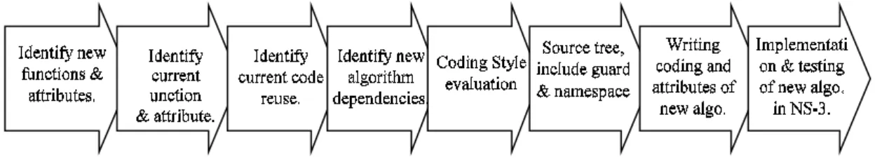
The development of AARF-HT algorithm in this research is done according to the development and implementation of new algorithm in NS-3 simulator [14] as shown in figure 4 as follows:
1. Identify the new functionality required for the implementation of the AARF-HT algorithm model and the attributes provided for the AARF-HT configuration. 2. Identify the functionality and attributes currently
available on the AARF algorithm model as in Fig. 3. 3. Identify the reusable parts of the AARF model currently
available.
4. Identify the dependencies required for the AARF-HT coding to be made.
5. Evaluate the NS-3 Simulator coding style for AARF-HT implementation.
6. Determination of source three on the NS-3 Simulator for placement of AARF-HT source code source in the NS-3 version 3.26 directory.
7. Determination of the include guard for AARF-HT. 8. Determination of AARF-HT Namespace for NS-3
Simulator.
9. Writing C++ coding for the implementation of functions required AARF-HT.
Figure 4. New algorithm development method in NS-3
Access Point (AP)
1 M 2 M 3 M
Station (STA)
100 M
10.Writing C++ coding for attribute implementation required AARF-HT.
11.Testing of AARF-HT algorithm implementation on NS-3.26. To test the implementation of new algorithms on NS-3, tools have been provided by running the command ./test.py. The implementation of the new algorithm is said to be successful if testing with ./test.py does not generate an error.
3.2 Simulation Method for AARF-HT Performance Evaluation
After the testing phase of AARF-HT algorithm implementation in NS-3 has succeeded and no more error message appeared, next is testing performance of AARF-HT algorithm in performing adaptation rate in WLAN IEEE 802.11n according to channel condition. The purpose of the testing phase is to ascertain whether all functions contained in the AARF-HT algorithm are functioning properly or not. Some functions of the AARF-HT algorithm to be tested such as MPDU transmission function using and without using AMPDU, MPDU transmission function using various combination of spatial stream number, Guard Interval size and channel bandwidth size as well as testing controlling the use of 802.11n data rate according to channel condition for resulting in optimal throughput.
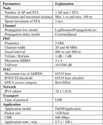
To test all the functions and attributes of the AARF-HT algorithm, a simulation is made using scenarios as shown in Figure 5. In the test simulation there is one Access Point (AP) and one Station (STA) that support IEEE 802.11n WLAN standard. Each PHY from AP and STA support usage of channel bandwidth of 20 MHz and 40 MHz at 5 GHz frequency, 800 ns and 400 ns Guard Interval support, and MIMO support up to four spatial streams. MAC AP and STA support AMPDU with a maximum size of 65535 bytes. In the AP there is a Constant Bit Rate (CBR) application that sends data packets of 1420 bytes continuously to the STA 1 meter (m) away from the AP. Then STA moves away from the AP at a speed of 1 meter per second (m/s) to a distance of 100 m from the AP. The data transmission throughput is measured at the STA per meter of movement in units of megabits per second (Mbps). The throughput of the AARF-HT algorithm is then compared with the Constant Rate throughput of each HtMcs data rate for AARF-HT performance to be evaluated. Other parameters used in the test simulations are shown in Table 2.
4.
Result and Discussion
In this section we describe the results of the development and performance evaluation of the AARF-HT algorithm.
4.1 Development of AARF-HT Algorithm
The 802.11n standard already has other parameters that can affect throughput of channel width, guard interval and number of spatial streams. Channel Width affects the magnitude of the throughput generated, whereby if the greater the channel width, the greater the throughput generated. In the 802.11n standard the channel width selection has two ranges of 20 and 40 MHz, Guard Interval will affect the waiting time for ACK reception, the smaller the ACK wait time will be the greater the throughput generated. This is because the shorter the time required for
decision making in case of frame fails.
In the 802.11n standard the guard interval selection is two times 400 ns and 800 ns. The number of spatial streams influences the throughput as the greater the number of spatial streams the greater the throughput will be generated. This is because more and more paths will be passed during the transmission process. In the 802.11n standard there are four choices of spatial stream usage that are 1, 2, 3 and 4.
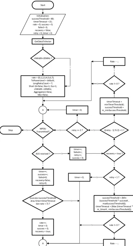
Based on these explanations and based on the AARF-HT algorithm development method described in Part III we have designed and implemented the AARF-HT algorithm in two new NS-3 files: manager.h and aarf-ht-wifi-manager.cc. Both files are placed in the directory /ns3.26/src/wifi/model/. The complete pseudo code implementation of the AARF-HT algorithm is shown in Pseudo code 1.
The AARF-HT pseudo code algorithm consists of four parts, the initialization part (lines 2-20), the functioning part of the successful transmission of MPDU transmission, without or using AMPDU (lines 23-48), the MPDU/AMPDU delivery failure checking function section (lines 51-70) and parts of the DataTxVector checking function (lines 72-97).
In the initialization section, we add new attributes that were not previously available on the AARF algorithm, which is chWidth (channel width), sgi (short guard interval), ss (number of spatial streams), and maxHtRateId (maximum number of ID of HT rate). These four attributes are used to identify the HT data rate list supported by STA and AP. Additionally we also added the nSuccessfulMpdus (number of successful transmission of MPDU) and
maxAMPDU (maximum size of AMPDU) attributes used when
a terminal enables AMPDU transmission mode. Table 2. Simulation Parameters
Parameters Explanation
Node
Number of AP and STA 1 AP and 1 STA Minimum and maximum distance Min. 1 m and max. 100 m Speed movement of STA 1 m/s
Channel
Propagation loss model LogDistancePropagationLoss Propagation delay model ConstantSpeed
PHY
Frequency 5 GHz
Channel width 20 and 40 MHz Guard interval 800 ns and 400 ns TxGain / RxGain 1 dB / 1 dB Maximum MIMO 4 x 4
TxPower 16.0206 dB
MAC
Maximum size of AMPDU 65535 byte RTS/CTS threshold 65535 byte (disable) EDCA access category Best Effort Network
IPv4 subnet 10.1.1.0/24 Transport
Type of protocol UDP Application
Application model OnOffApplication Packet size 1420 byte
CBR 600 Mbps
In AARF-HT, for each received ACK then the value of the success attribute will be updated depending on whether the MPDU is sent using AMPDU or not. If not, then the attribute value success is incremented. But if using AMPDU, then the value of attribute success summed with nSuccessfulMpdus. So, MPDU transmission using AMPDU can accelerate the attribute's success value to its threshold value. If the success is greater than or equal to successThreshold and the current
rate (index rate) is smaller than maxHtRateId then AARF-HT increments the rate index.
For any MPDU/AMPDU transmission failure, AARF-HT increment failed attribute. Then checked, if state in recovery condition and retry equal to 1 then update the value of
successThreshold and timerTimeout. Update
successThreshold value is done by selecting a smaller value between successThreshold multiplication with
successK or maxSuccessThreshold. Update
timerTimeout value is done also by selecting bigger value
between timerTimeout multiplication with TimerK or
minSuccessThreshold. The decrement is then performed
on the index rate if the current rate index is not equal to zero. But if the retry-1 modulus 2 equals 1 is fulfilled then updates to the successThreshold and timerTimeout values are performed as follows: timerTimeout is equal to
minTimerThreshold and successThreshold is equal to
minSuccessThreshold. The decrement is then performed
on the index rate if the current rate index is not equal to zero. The GetDataTxVector() function is used to specify the transmission TxVector parameter of an MPDU/AMPDU. This function begins with a function calling GetChWidth(),
GetShortGuardInterval()and
GetNumberOfSupport-Antenna() to obtain channel bandwidth, guard interval and
Pseudocode 1. AARF-HT algorithm
1: 2: 3: 4: 5: 6: 7: 8: 9: 10: 11: 12: 13: 14: 15: 16: 17: 18: 19: 20: 21: 22: 23: 24: 25: 26: 27: 28: 29: 30: 31: 32: 33: 34: 35: 36: 37: 38: 39: 40: 41: 42: 43: 44: 45: 46: 47: 48: 49: 50: 51: 52: 53: 54: 55: 56: 57: 58: 59: 60: 61: 62: 63: 64: 65: 66: 67: 68: 69: 70: Initialization:
maxSuccessThreshold = 60 minSuccessThreshold = 10 minTimerThreshold = 15 successK = 2; timerK = 2 rate = 0
success = 0 failed = 0 recovery = false retry = 0 timer = 0
successThreshold = minSuccessThreshold timerTimeout = minTimerThreshold chWidth = 0
sgi = true ss = 0
maxHtRateId = 0 nSuccessfulMpdus = 0 maxAMPDU = 0 GetDataTxVector ()
For each ACK:
begin
if maxAMPDU < 2 × MPDU then timer++
success++ failed = 0 recovery = false retry = 0
if ((success = successThreshold || timer = timerTimeout) && (rate < maxHtRateId)) then
rate++ timer = 0 success = 0 recovery = true else
success += nSuccessfulMpdus failed = 0
recovery = false retry = 0
if ((success >= successThreshold) && (txrate < maxHtRateId)) then rate++
timer = 0 success = 0
nSuccessfulMpdus = 0 recovery = true end
For each packet loss:
begin timer++ failed++ retry++ success = 0 if recovery=true then if (retry = 1) then
successThreshold = (Min (successThreshold × successK, maxSuccessThreshold));
timerTimeout = (Max (timerTimeout × timerK, minSuccessThreshold)) if (m_rate != 0) then rate-- timer = 0
else
if (((retry - 1) % 2) == 1) then timerTimeout = minTimerThreshold successThreshold = minSuccessThreshold if (rate != 0) then rate--
if (retry >= 2) then timer = 0 end
Pseudocode 1. AARF-HT algorithm (continued)
71: 72: 73: 74: 75: 76: 77: 78: 79: 80: 81: 82: 83: 84: 85: 86: 87: 88: 89: 90: 91: 92: 93: 94: 95: 96: 97: GetDataTxVector () begin
chWidth = GetChannelWidth () sgi = GetShortGuardInterval () maxAMPDU = GetAggregation ()
streams = GetNumberOfSupportedRxAntennas ()
if (chWidth=40 && sgi=true && ss=4) then rate = {0 ~ 127) if (chWidth=40 && sgi = true && ss = 3) then rate = {0 ~ 95) if (chWidth=40 && sgi = true && ss = 2) then rate = {0 ~ 63) if (chWidth=40 && sgi = true && ss = 1) then rate = {0 ~ 31) if (chWidth=40 && sgi = false && ss=4) then rate = {0 ~ 63) if (chWidth=40 && sgi = false && ss=3) then rate = {0 ~ 47) if (chWidth=40 && sgi = false && ss=2) then rate = {0 ~ 31) if (chWidth=40 && sgi = false && ss=1) then rate = {0 ~ 15) if (chWidth=20 && sgi = true && ss=4) then rate = {0 ~ 63) if (chWidth=20 && sgi = true && ss=3) then rate = {0 ~ 47) if (chWidth=20 && sgi = true && ss = 2) then rate = {0 ~ 31) if (chWidth=20 && sgi = true && ss = 1) then rate = {0 ~ 15) if (chWidth=20 && sgi = false && ss=4) then rate = {0 ~ 31) if (chWidth=20 && sgi = false && ss=3) then rate = {0 ~ 23) if (chWidth=20 && sgi = false && ss=2) then rate = {0 ~ 15) if (chWidth=20 && sgi = false && ss=1) then rate = {0 ~ 7) maxHtRateId = (8 × (chWidth/20) × (sgi+1) × (streams)) - 1 return WifiTxVector (rate, GetDefaultTxPowerLevel (),
GetLongRetryCount (), sgi, streams, 0, channelWidth, GetAggregation (), false)
the number of antennas used by the transmitter. From the information then made a list of tramsiter index rate. For example, if chWidth = 20, sgi = false and streams = 1 then the available rate index is 0-7, that means the transmitter has a choice of data rate 6.5 to 65 Mbps. However if chWidth = 40, sgi = true and streams = 4 then the available rate index is 0-127 or available data rate options up to 600 Mbps. This function also calculates the maximum index of the data rate stored in the maxHtRateId variable. The final part of this function returns the value of the TxVector parameter used for MPDU/AMPDU transmission. After the testing phase of AARF-HT algorithm implementation in NS-3 has succeeded and no more error message appeared, next is testing performance of AARF-HT algorithm in performing rate adaptation in WLAN IEEE 802.11n according to channel condition. When the ./test.py command is executed then the NS-3 simulator compiles the entire build module file program found in the NS-3 simulator. We have tested the implementation of the AARF-HT algorithm using the ./test.py tool. The test results show the AARF-HT has been running well where "399" passed, "3" skipped, "0" failed, "0" crashed and "0" valgrind errors.
4.2 AARF-HT Performance Evaluation
Figure 6 shows the AARF-HT rate adaptation simulation results in the IEEE 802.11n WLAN where MPDU transmission is performed without using the AMPDU scheme. In the simulation, 40 MHz channel width has been used, SGI has enabled and the maximum number of streams used is 4. Based on the implementation of AARF-HT algorithm as shown in Pseudo code 1, AP and STA have 128 data rate options such as shown in Table 1. The simulation results show, when the STA is at a distance of 1 m from the AP and MPDU begins to be transmitted using the data rate with index rate = 0, resulting in a throughput of 25 Mbps.
Then when the STA is at a distance of 2 m from the AP, the throughput starts rising to 34 Mbps to match the throughput generated by the HtMcs-31 data rate up to a distance of approximately 20 m. This increase in throughput occurs because at that distance each MPDU transmission is successful so AARF-HT continues to increase the index rate until it reaches data rate equal to HtMcs-31. However, after passing the distance of 20 m, the throughput began to decrease as a result of channel quality decreased so that AARF-HT adjusted the data rate according to the channel condition.
At a distance of 20 to 100 meters, AARF-HT managed to adapt the 802.11n rate according to the channel conditions. This success is evidenced by the resulting throughput matching the optimal throughput generated by HtMcs-24 to Ht-Mcs31 data rates. When channel quality changes, the throughput generated by AARF-HT decreases, but again achieves the throughput generated by the constant rate. Therefore it can be said that MPDU transmission function without AMPDU and adaptation of data rate based on channel condition successfully performed by AARF-HT algorithm.
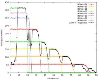
Figure 7 shows the simulation results of AARF-HT rate adaptation in the IEEE 802.11n WLAN where MPDU transmission is performed using the AMPDU scheme. The PHY parameters used are the same as those generated by Figure 6 which are 40 MHz channel widths, using SGI and using a maximum of 4 spatial streams resulting in 128 data rate options. The simulation results show, when STA is at a distance of 1 m from AP and AMPDU begin to be transmitted using data rate with index rate = 0 yielding 25 Mbps throughput. However when STA is at a distance of 2-10 m from the AP, the throughput rises to 425 Mbps to match the throughput generated by the HtMcs-31 data rate up to a distance of approximately 20 m.
Figure 7. Throughput of AARF-HT vs. constant rate (AMPDU = enable; channel width = 40 MHz; SGI = true; streams = 4)
This increase in throughput occurs because at that distance every success AMPDU delivery so that AARF-HT continues to increase the index rate to achieve the data rate HtMcs-31. However, after passing a distance of 20 m, the throughput began to decrease as a result of channel quality decreased so that AARF-HT re-adjusted the data rate used for AMPDU delivery in accordance with channel conditions.
The throughput generated by the AARF-HT algorithm shown in Figure 7 is much higher than the throughput shown in Figure 6. This condition proves that the MPDU delivery function using AMPDU scheme in AARF-HT algorithm has functioned well and AMPDU scheme capable to increase throughput in 802.11n network. However the throughput generated at a distance of 1 m is still low due to AARF-HT always transmits AMPDU with index rate equal to 0. So it takes several seconds to achieve the optimal throughput generated by index rate = 127 using HtMcs-31 data rate. Figure 8, Figure 9 and Figure 10 show the throughput generated by the AARF-HT algorithm using a combination of
channel width, guard interval and the number of different spatial streams. The throughput shown in Figure 8 is generated by the AARF-HT algorithm where MPDU transmission is performed using the AMPDU scheme, using 20 MHz bandwidth, SGI and using four spatial streams. Based on the use of the combination of PHY parameters, AARF-HT has 64 data rate options that can be used to transmit AMPDU. When the STA is at a distance of 1 m from the AP, the resulting throughput is 25 Mbps. However at a distance of 5-20 m, the throughput is increase of up to 248 Mbps equals the throughput generated by the HtMcs-31 constant rate. As the STA continues to move away from the AP up to a distance of 100 m, the throughput generated by the AARF-HT algorithm can match the optimal throughput of the HtMcs constant rate.
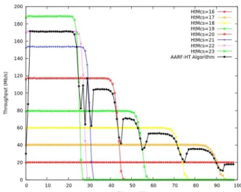
The throughput shown in Figure 9 and Figure 10 is generated by the AARF-HT algorithm where MPDU transmission is performed using the AMPDU scheme, using 20 MHz bandwidth and 800 ns GI. However Figure 9 uses 3 spatial
Figure 8. Throughput of AARF-HT vs. constant rate Figure 9. Throughput of AARF-HT vs. constant rate (AMPDU = enable; channel width = 20 MHz; SGI = true; (AMPDU = enable; channel width = 20 MHz; SGI = false; streams = 4). streams = 3).
Figure 10. Throughput of AARF-HT vs. constant rate Figure 11. Throughput of AARF-HT vs. AARF algorithm (AMPDU = enable; channel width = 20 MHz; SGI = false;
streams and Figure 10 uses 2 spatial streams. Based on the use of the combination of PHY parameters, AARF-HT in Figure 9 has 24 data rate options and in Figure 10 has 16 data rate options that can be used to transmit AMPDU. When the STA is at a distance of 1 m from the AP, the resulting throughput is 25 Mbps. However, when using 3 spatial streams at a distance of 2-20 m throughput an increase of up to 175 Mbps matches the resulting throughput of HtMcs-23 constant rate. As the STA continues to move away from the AP up to a distance of 100 m, the throughput generated by the AARF-HT algorithm can match the optimal throughput of the HtMcs-22, HtMcs-21 to HtMcs-16 constant rates. Similarly, when using 2 spatial streams at a distance of 2-20m, the throughput is increase of up to 119 Mbps also matches the throughput generated by the HtMcs-15 constant rate. As the STA continues to move away from the AP up to a distance of 100 m, the throughput generated by the AARF-HT algorithm can match the optimal throughput of the HtMcs-14 to HtMcs-8 constant rate. Thus Figure 8, Figure 9 and Figure 10 prove that the MPDU delivery function uses various combinations of channel bandwidth size, SGI = true or false and the number of different spatial streams have the AARF-HT algorithm working properly.
Figure 11 shows the comparison of AARF-HT algorithm throughput with various MAC and PHY configurations and the AARF algorithm. The AARF-HT algorithm generates a higher throughput than the AARF algorithm either without using AMPDU or using AMPDU. The throughput generated from the HT using AMPDU is higher than the AARF-HT without using AMPDU. Figure 11 also shows that throughput is strongly influenced by channel width, guard interval and number of spatial streams used. Based on figure 11 it can be seen that the 40 MHz channel width produces a higher throughput than at 20 Mhz. Use of 400 ns Guard intervals (activated using Boolean sgi = true) results in lower throughput of guard interval = 800 ns (activated using Boolean sgi = false). Furthermore, four spatial streams result in higher throughput than three spatial streams, three spatial streams resulting in higher throughput than two spatial streams and two spatial streams resulting in higher throughput than a single spatial stream.
5.
Conclusions
We have improved the AARF algorithm to be used in the IEEE 802.11n WLAN and call it the AARF-HT algorithm. In the AARF-HT algorithm we have added the chWidth, sgi, streams and maxHtrateId attributes. The attributes are used by the GetDataTxVector() function in order for AARF-HT to know the channel width, guard interval, number of spatial streams and the maximum number of indexes supported by HT-PHY. The AARF-HT algorithm has also added the maxAMPDU and nSuccessfulMpdus attributes. The maxAMPDU attribute is used by the
GetDataTxVector() function in order for AARF-HT to
know the maximum size of AMPDU. The nSuccessfulMpdus attribute is used by the function of checking the success of MPDU transmission using AMPDU so that AARF-HT can know the number of MPDU received without error. The results of the AARF-HT rate adaptation
simulation on the IEEE 802.11n WLAN, where MPDU transmission is performed without and using the AMPDU scheme, has worked well. This is evidenced by the throughput generated AARF-HT has been able to adapt to changes in channel quality and generate maximum throughput in accordance with the constant rate. MPDU transmission function test results using various combinations of channel width, guard intervals and different spatial stream numbers show the AARF-HT algorithm is working properly. AARF-HT has also generated maximum throughput constant rate. The simulation results also show that the throughput of AARF-HT algorithm is higher than AARF.
References
[1] IEEE, “Standard for Wireless LAN Medium Access Control (MAC) and Physical Layer (PHY) Specifications Amendment 5: Enhancements for Higher Throughput,” IEEE Std 802.11n-2009, vol., no., pp.1-565, Oct. 29 2009.
[2] F. Fietkau and D. Smithies, “Linux Wireless Minstrel High Throughput.,” Minstrel-Ath9k driver http://linuxwireless.org/en/users/Drivers/ath9k.
[3] D. Nguyen and J. J. Garcia-Luna-Aceves, “A practical approach to rate adaptation for multi-antenna systems,” 2011 19th IEEE International Conference on Network Protocols, Vancouver, BC, 2011, pp. 331-340. [4] A. B. Makhlouf and M. Hamdi, “Practical Rate
Adaptation for Very High Throughput WLANs,” in IEEE Transactions on Wireless Communications, vol. 12, no. 2, pp. 908-916, February 2013.
[5] I. Pefkianakis, S. B. Lee and S. Lu, “Towards MIMO-Aware 802.11n Rate Adaptation,” in IEEE/ACM Transactions on Networking, vol. 21, no. 3, pp. 692-705, June 2013.
[6] S. Seytnazarov and Young-Tak Kim, “Cognitive rate adaptation for high throughput IEEE 802.11n WLANs,” 2013 15th Asia-Pacific Network Operations and Management Symposium (APNOMS), Hiroshima, Japan, 2013, pp. 1-6.
[7] R. Karmakar, S. Chattopadhyay and S. Chakraborty, “Dynamic link adaptation for High Throughput wireless access networks,” 2015 IEEE International Conference on Advanced Networks and Telecommuncations Systems (ANTS), Kolkata, 2015, pp. 1-6.
[8] M. I. Hasan and S. Kumar, “Spectral Efficiency Evaluation for Selection Combining Diversity Schemes under Worst Case of Fading Scenario,” International Journal of Communication Networks and Information Security, Vol. 7, No. 3, pp. 123-130, 2015.
[9] M. Yazdani, M. Kamali, N. Moghim and M. Ghazvini, “A Fair Access Mechanism Based on TXOP in IEEE 802.11e Wireless Networks,” International Journal of Communication Networks and Information Security, Vol. 8, No. 1, pp. 11-17, 2016.
[10]M. Lacage, M.H. Manshaei, and T. Turletti, “IEEE 802.11 rate adaptation: a practical approach,” Proceedings of the 7th ACM international symposium on Modeling, analysis and simulation of wireless and mobile systems, pages 126–134, 2004.
band,” Wireless Bell Labs technical journal, 2(3):118– 133, 1997.
[12]Cerowrt, The Cerowrt site (2017), Internet (online), http://blog.cerowrt.org/papers/minstrel-sigcomm-final.pdf.
[13]Nsnam, The Network Simulator NS-3 site (2017), Internet (online), https://www.nsnam.org
[14]Nsnam, The NS-3 Manual, Internet (online), https://www.nsnam.org/docs/release/3.27/manual/ns-3-manual.pdf
[15]T. Y. Arif, R. Munadi and Fardian, “Evaluation of the Minstrel-HT Rate Adaptation Algorithm in IEEE 802.11n WLANs,” International Journal of Simulation Systems, Science & Technology, Vol. 18, No. 1, pp. 11.1-11.7, March 2017.
[16]S. H. Wong, H. Yang, S. Lu, and V. Bharghavan, “Robust rate adaptation for 802.11 wireless networks,” in Proc. ACM MobiCom, 2006, pp. 146–157.
[17]J. Camp and E. Knightly, “Modulation rate adaptation in urban and vehicular environments: Cross-layer implementation and experimental evaluation,” in Proc. ACM MobiCom, 2008, pp. 315–326.
[18]G. Judd, X. Wang, and P. Steenkiste, “Efficient channel-aware rate adaptation in dynamic environments,” in
Proc. ACM MobiSys, 2008, pp. 118–131.
[19]H. Rahul, F. Edalat, D. Katabi, and C. Sodini, “Frequency-aware rate adaptation and MAC protocols,” in Proc. ACM MobiCom, 2009, pp. 193–204.
[20]S. Byeon, K. Yoon, O. Lee, W. Cho, S. Oh, and S. Choi, “MoFA: Mobility-Aware Frame Aggregation in Wi-Fi,” in Proc. ACM CoNEXT, Dec. 2014.