UDC 629.463.027.23
O. A. SHYKUNOV
1*1*Dep. «Cars and Cars Facilities», Dnipropetrovsk National University of Railway Transport named after Academician V. Lazaryan, Lazaryan St., 2, Dnipro, Ukraine, 49010, tel. +38 (056) 373 15 04, e-mail [email protected], ORCID 0000-0002-8256-2634
THREE-ELEMENT BOGIE SIDE FRAME STRENGTH
Purpose. To evaluate the effect of different loads on the stress-strain state of the freight car bogie side frame, as well as to evaluate the distribution of the stress fields in the design of the freight car bogie side frame supported through the horizontal surface and through the horizontal and inclined surfaces of the pedestal opening. Methodol-ogy. A volumetric finite element model of the side frame of ZK-1 bogie of the freight car was designed. The forces under the current regulatory documentation for theoretical research were applied to the model, the stress arising in the model elements were determined. The static tests of ZK-1 bogie side frame were conducted; they allowed de-termining the stresses in the key points of the frame under the action of forces in accordance with the existing pro-cedure of static tests of the freight car bogie side frame. To check the quality of the finite element model we deter-mined the stress in the model under the action of forces corresponding to the static requirements. The corresponding coefficients were determined to match the stress obtained through theoretical studies and static tests. The results of theoretical and experimental studies of stress for dangerous sections of the side frame design were compared. Findings. The regulatory documentation for carrying out experimental research of the side frame strength does not fully take into account the load acting on the frame during its operation and that provided while assessing the side frame strength theoretically. The strength evaluation of the side frame by the results of field tests only does not give a complete picture of the distribution of stress fields, as the provided sensor installation points do not cover most of the design elements with possible stress concentration. Originality. The loads applied to the side frame during theo-retical and experimental studies were compared to the loads acting during operation. The impact of use of inclined surfaces in the pedestal box opening was evaluated. Practical value. The obtained results allow the more accurate assessment of the three-piece bogie side frame strength, as well as allow you to choose the more preferred method of side frame support in the axle box.
Keywords: side frame; three-piece bogie; strength; test; calculation; support
Introduction
The strength of new and upgraded designs of car elements is assessed using the experimental and theoretical studies. Each car element must pass these two stages, and for each of them there are developed regulations governing the load to be applied to the object during theoretical and ex-perimental studies [3, 7, 8, 10].
For freight car three-piece bogie side frame such documents are «Regulations for calculation and design of cars of 1520mm gauge railways of Ministry of Railways (non-self-propelled)» [8] for theoretical studies and «Bolsters and cast side frames of four-wheel bogie of freight cars for 1520 mm track. Methods of static strength tests» [7] for the experimental ones.
However, the loads under which the stress-strain state of the side frame is studied during theo-retical and experimental studies differ in both val-ue and place of application. And if the difference
between the values of the existing loads can be compensated by appropriate co-coefficients, it is much more complicated to compensate the differ-ence in places of load application, which leads to difficulties in comparing the results of experimen-tal and theoretical studies.
Development of Ukrzaliznytsia rolling stock and that of the CIS countries in recent years is aimed at increasing the efficiency of cars, not only due to speeding up [6], but also due to their higher carrying capacity by increasing the axle load from 23.5 ton/axle to 25 tons/axle [ 4, 5, 13, 18].
the bogie and its side frame as one of the elements [11].
An alternative to increased strength of bogie components is reduced dynamic effects on the bogie during movement. This effect is achieved in various ways, such as: the use of a bilinear spring suspen-sion at the central core stage, the improvement of friction pairs in the friction wedge-type shock ab-sorber, installation of additional connections be-tween the bogie side frames, etc. [2, 12, 15, 16, 17]. One of the ways to reduce the dynamic compo-nent of the load acting on the side frame is to in-stall the second suspension stage between bogie side frame and the wheelset axle box. This assem-bly is set with an elastic spring element, polyure-thane, rubber or rubber-metal gasket. This element can receive and transmit further both exclusively vertical forces and vertical and horizontal forces.
If to take up the first ones, the horizontal sup-port surfaces in the pedestal opening of the bogie side frame are enough, then to transmit the hori-zontal forces, it is necessary to provide for the presence of the elastic element between the vertical support surfaces. Realizing such a support way it is necessary to prevent from elastic element falling out of the space between the vertical support sur-faces, by means of its additional fastening, which leads to complicated construction in the place of interaction of side frame and axle box. An alterna-tive is to set the elastic elements on inclined sur-faces for taking up the vertical and horizontal loads by one and the same elastic element. For this pur-pose, it is necessary to provide for appropriate support surfaces both of the axle box housing and in the pedestal opening or to use adapters. The sec-ond way is not effective, although it leads to in-creased side frame unification, but the presence of additional elements results in reduced work space in the pedestal opening and sizes of the elastic gas-ket.
The transition from boxes to the cassette type bearings and the axle box adapters allows aban-doning the unified box housing and applying axle box adapters with different surfaces for side frame supporting.
The need for inclined support surfaces in the pedestal opening also involves changes in the bo-gie side frame, and transfer of the horizontal loads or most of them through the upper member of the pedestal opening leads to the redistribution of
stresses in the side frame and the need of strength-ening in the places not critical for frames with sep-arate load transfer.
Purpose
The purpose of the work is to evaluate the ef-fect of different loads on the stress-strain state of the freight car bogie side frame, as well as to eval-uate the distribution of the stress fields in the de-sign of the freight car bogie side frame supported through the horizontal surface and through the hor-izontal and inclined surfaces of the pedestal open-ing.
Methodology
The study was conducted for the side frame of the three-piece bogie of ZK-1 model made in Chi-na.
ZK-1 bogie side frame has the construction typ-ical for three-piece bogie side frames – it consists of upper, lower, diagonal members and 2 columns. Support on wheelsets is through pedestal openings, the upper surface of which is 2-pitch with a hori-zontal platform in the middle. The central opening of the side frame houses a set of 9 2-row suspen-sion springs. The friction shock absorber plates are mounted on the inner surface.
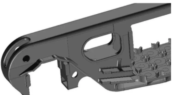
To evaluate the stress-strain state of the side frame the finite element model is developed. There are applied solid 10-unit elements with a character-istic edge size of 10 mm. Dimensions of the ele-ments vary in model volume and decrease in the places of openings, radius transitions and other potential stress raisers. The element size is chosen so that its further change would have no effect on the calculation results. The modelling process first created the three-dimensional geometrical model (Fig. 1), which was automatically divided into three-dimensional finite elements (Fig. 2). The re-sulting finite element model of the bogie has 664,705 elements, 1,789,864 units and 5,369,592 degrees of freedom.
For model material, the following values of the elastic constants of the material are assumed: Young’s modulus E = 210 GPa, Poisson’s ratio
0.27
v .
Fig. 1. Geometric model of ZK-1 bogie side frame
Fig. 2. Detail of the finite element model of ZK-1 bogie side frame
Vertical loads are as follows: – Vertical static load, – Vertical dynamic load,
– Vertical contribution of longitudinal inertia force of the car,
– Vertical contribution of braking force,
– Vertical contribution of forces of inertia in the curve and wind pressure strength.
Side loads are as follows:
– Wind pressure forces and centrifugal force during the passage curved track sections,
– Transverse component of longitudinal quasi-static force,
– Frame force.
Longitudinal loads are as follows: – Bogie mass inertia force, – Brake force,
– Thrust force of friction wedges.
These loads are grouped in six variants of load-ing that correspond to:
a) the forces acting on the car during its colli-sion with the train when breaking-up from a hump; b) the forces acting on the car in the middle of the train with braked front cars and not braked, approaching from the rear cars;
c) the forces acting on the last car moving with the design speed in the train during adjusting brak-ing at the beginnbrak-ing of the curved section;
d) the forces acting on the last car moving with the design speed in the train during adjusting brak-ing at the straight track section;
e) the forces acting on the car moving with the design speed in the train during adjusting braking in a curve, with braked front cars and not braked, approaching from the rear cars;
f) the forces acting on the car moving with the design speed in the train during adjusting braking in a curve.
The I design mode corresponds to the variants of loading a and b, III – c … f.
Table 1 shows the values and points of origin of the maximum stress in the bogie side frame.
Table 1 The maximum stresses in the bogie side frame, MPa
Variant of
load-ing Point of origin
Limit
values Calculated value
a Lower angles of the central spring open-ing
250 240
b Vertical support surface of the pedes-tal opening
250 235
c Lower angles of the central spring
open-ing 140 132
d
Vertical support surface of the
pedes-tal opening 140 137
e Vertical support surface of the pedes-tal opening
140 139
f Lower angles of the central spring
open-ing 140 131
This side frame also underwent the complex of static strength tests according to [7]. Tests were carried out on the territory of Qiqihar Railway Rolling Stock Co. Ltd. (PRC) on the testing ma-chine ZDM 200Pu.
schemes were registered. For the side frames of the cars with 245 kN axle load there are the following values of the test loads and the places of their ap-plication:
1 – vertical load of 490 kN uniformly applied to support places of the central group springs;
2 – horizontal load of 147 kN applied on the outer side of the frame to one of the columns of the central spring opening;
3 – horizontal loads of 73.5 kN each applied on the outer side of the frame to both columns of the central spring opening;
4 – horizontal loads of 122 kN each applied to the friction plates of the central spring opening;
5 – horizontal loads of 66 kN each applied to the vertical surfaces of the pedestal opening.
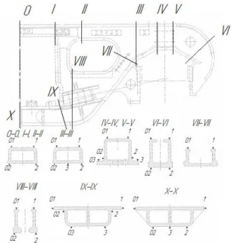
To check the adequacy of the finite element model of the real side frame, the calculations were conducted, in which the finite element model was subjected to the loads similar to the experimental ones, and the calculation resulting stresses were compared with those obtained during the tests [14]. Figure 3 shows the control sections and the sensor installation location during the test.
Fig. 3. Layout of strain sensors for static tests
Comparison of calculation and test results for some check points is given in Table 2.
As can be seen from Table 2 the results of theo-retical studies are in good agreement with the test results, indicating the adequacy of the finite ele-ment model and the real side frame.
To compare the results of theoretical studies according to the «Regulations…» [8] and the ex-periment according to the method [7], there were calculated the correlation coefficients of the loads applied during testing and load combinations that act on the side frame according to the «Regu-lations…». These coefficients are presented in Table 3.
Table 2 Stresses in check points during testing
and theoretical modelling
Stresses during loading by scheme, MPa Section-point
1 2
-54.23 -42.73 0-2
-47.73 -44.46 -48.10 44.83 0-02
-49.80 40.66 -81.83 -99.67 І-2
-86.59 -125.93 -73.80 -43.03 I’-2
-97.82 -59.88 94.23 -0.57 ІІІ-2
108.34 23.34 68.43 -15.47 III’-2
109.69 16.40 93.00 8.23 III’-02
115.24 -16.99 -72.30 -10.70 VIII’-1
-70.25 -14.47 31.50 -164.40 IX-1
44.59 -112.94 22.23 103.60 IX-01
67.82 165.31 100.10 17.87 X-02
End of table 2
Stresses during loading by scheme, MPa
Section-point 3 4 5
-41.13 -22.17 -0.30 0-2
-26.13 -21.26 -0.60 38.7 21.83 -0.70 0-02
23.82 19.79 -0.53 -57.50 24.83 -3.23 І-2
-53.00 30.29 -2.61 -67.77 21.90 0.60 I’-2
-61.66 35.38 0.74 -8.50 -3.37 23.40 ІІІ-2
11.85 -4.50 24.81 -11.43 -2.47 0.07 III’-2
11.94 -4.63 0.01 3.73 -3.23 0.10 III’-02
-12.52 -4.46 0.01 -20.67 -30.00 0.03 VIII’-1
-18.41 -29.97 0.06 -132.20 9.23 -0.73 IX-1
-54.39 11.05 -0.87 84.83 11.53 -0.97 IX-01
84.93 11.07 -1.00 17.10 -0.70 -0.13 X-02
9.42 -1.33 0.14
Note: The numerator shows the values obtained from the tests, the denominator – those from theoretical studies.
The use of the coefficients shown in Table 3 al-lows converting the stresses obtained during the static test to compare them with the results of theoretical studies by the formula:
, i kij j
where i – stresses obtained during the static tests by the j -th loading scheme, MPa; kij – coefficient taking into account the ratio of the forces applied by the j -th loading scheme of the static tests and the i
-th variant of loading of -the -theoretical studies; i – variant of loading during theoretical studies, i=1, 2, … ,6; j – loading scheme for static tests, j=1, 3, 4, 5.
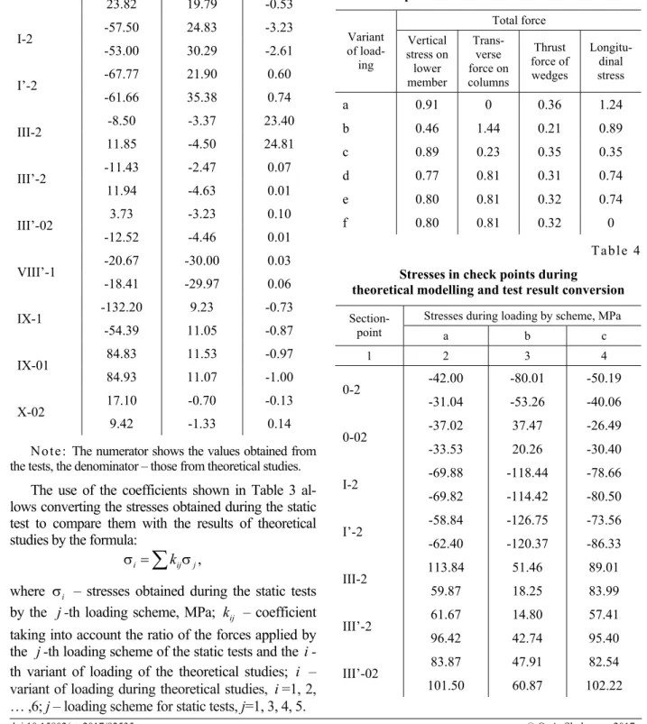
Table 4 shows the stresses obtained at the check points during the theoretical study of stress-strain state of the side frame according to the «Regula-tions…» (denominator) and the ones resulting from conversion of the test results, taking into account the coefficients of Table 3 (numerator).
Table 3 Load ratio during theoretical
and experimental studies of the side frame
Total force Variant of load-ing Vertical stress on lower member Trans-verse force on columns Thrust force of wedges Longitu-dinal stress
a 0.91 0 0.36 1.24
b 0.46 1.44 0.21 0.89
c 0.89 0.23 0.35 0.35
d 0.77 0.81 0.31 0.74
e 0.80 0.81 0.32 0.74
f 0.80 0.81 0.32 0
Table 4 Stresses in check points during
theoretical modelling and test result conversion
Stresses during loading by scheme, MPa
Section-point a b c
1 2 3 4 -42.00 -80.01 -50.19 0-2
-31.04 -53.26 -40.06 -37.02 37.47 -26.49 0-02
-33.53 20.26 -30.40 -69.88 -118.44 -78.66 І-2
-69.82 -114.42 -80.50 -58.84 -126.75 -73.56 I’-2
-62.40 -120.37 -86.33 113.84 51.46 89.01 ІІІ-2
59.87 18.25 83.99 61.67 14.80 57.41 III’-2
96.42 42.74 95.40 83.87 47.91 82.54 III’-02
Continuation table 4
Stresses during loading by scheme, MPa
Section-point a b c
1 2 3 4 -76.62 -69.63 -79.56 VIII’-1
-65.16 -57.51 -68.07 31.13 -174.64 0.33 IX-1
45.69 -78.17 -33.83 23.18 134.16 43.12 IX-01
68.29 161.82 85.80 55.45 10.85 51.24 X-02
90.45 30.18 86.21
End of table 4
Stresses during loading by scheme, MPa
Section-point d e f
1 5 6 7 -68.25 -69.66 -69.43 0-2
-49.19 -50.80 -53.78 0.73 -0.63 -0.11 0-02
-9.32 -11.05 -13.98 -104.01 -106.25 -103.85 І-2
-103.14 -106.17 -105.69 -104.24 -106.24 -106.68 I’-2
-108.12 -111.52 -120.42 81.60 84.65 67.29 ІІІ-2
57.22 61.55 84.53 42.44 44.66 44.61 III’-2
79.68 84.08 85.56 73.32 76.31 76.24 III’-02
90.36 94.96 96.52 -81.34 -84.05 -84.08 VIII’-1
-68.11 -71.04 -73.77 -80.70 -79.30 -78.76 IX-1
-42.58 -42.47 -41.59 88.60 89.31 90.03 IX-01
127.45 130.21 129.57 36.77 38.78 38.76 X-02
67.41 71.53 71.88
Note: The numerator shows the values obtained from conversion of the test results, the denominator – the results of theoretical studies.
As can be seen from Table 4 between the sults of theoretical studies and the converted re-sults of the experiment there is the large enough, sometimes more than 100%, discrepancy. For ex-ample, at III-2 section for the variants of loading a
and b the experimental-converted stresses exceed the theoretical ones by 1.9 and 2.8 times, while for the variant of loading c they are almost equal. For the section ІІІ’-2, located symmetrically in relation to the vertical transverse plane, under the same variants of loading the experimental-converted stresses are 1.5 and 2.9 times below the theoretical ones. At the same time there are no significant dif-ferences between the sections under the action of individual components of the test load (see Table 2). This is due to the fact that the variants of load-ing a and b correspond to the I-calculation mode and the longitudinal load, taken into account in theoretical studies, is high enough for these vari-ants. Simulation of action of bogie mass inertia force and brake force is not provided by the tests. When these forces are applied to one of the friction plate surfaces, the side frame thrusts against one pedestal opening with its inner vertical surface, while with its external surface in the other opening [9]. This causes not symmetrical loading of the side frame and leads to redistribution of stresses in the structure. It is not correct to replace the action of these forces with the test results when subjected to thrust loads in the central and the pedestal open-ing, since during such loadings the side frame sec-tion between the column and the pedestal opening practically does not work because there is no ten-sile or compressive load on it.
Also, the stress field distribution analysis revealed that the sensor location points on the bogie side frame given in [7] even though located in the most loaded sections, however, they often do not provide a com-plete picture of the maximum stress values arising in these sections. The stresses occurring in the check section or near it may exceed two or more times the value at the sensor location point (Fig. 4).
Fig. 4. Stress distribution in the cross section 0 on the side frame upper member:
A – sensor installation location (~34.4 MPa);
B – areas with high stress (64.4 MPa)
Besides, the volume model was created for this side frame; it is shown in Figure 4, as well as the finite element model (Fig. 5). The solid 10-unit elements with a characteristic edge size of 10 mm were used. The resulting finite element model of the bogie has 812,400 elements 1,290,310 units and 3,870,930 degrees of freedom.
Fig. 5. Geometrical model of the bogie side frame with horizontal support surfaces
Fig. 6. Detail of finite element model of the bogie side frame with support surfaces
Comparison of stress distribution in the side frames was carried out under the action of vertical load only, which corresponded to the first variant of loading during the test – 490 kN load, applied evenly to the spring support places of the central spring group, as this load contributes the major component into the stress-strain state of the side frame.
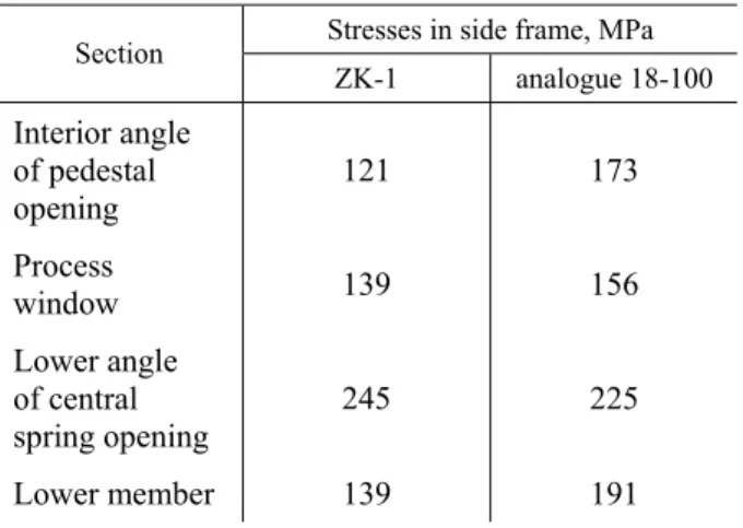
Comparison of stresses in the side frames is shown in Table 5.
Table 5 Stresses in the side frame elements
during the action of vertical load of 490 kN
Stresses in side frame, MPa Section
ZK-1 analogue 18-100
Interior angle of pedestal
opening 121 173
Process
window 139 156
Lower angle of central spring opening
245 225
Lower member 139 191
The presence of ramps in the section of transition from the inclined member to the upper member of the pedestal opening increased the cross-sectional area near the interior angle of the axle box opening, thus reducing the stress on this section. Also, it reduced stress in the area of process window and lower member, but increased their value in the lower angle of the central spring opening.
Findings
The strength evaluation of the three-piece bogie side frame when modelling loads during the field tests according to [7] does not consider in full the total load acting on the frame during its operation and provided for theoretical evaluation of the side frame strength [8].
Application of the inclined support surfaces in axle box opening reduces stress in its interior an-gle.
Originality and practical value
The loads applied to the side frame during theo-retical and experimental studies were compared to the loads acting during operation.
For the first time the impact of use of inclined surfaces in the pedestal box opening was evalu-ated.
The obtained results allow the more accurate assessment of the three-piece bogie side frame strength, as well as allow you to choose the more preferred method of side frame support in the axle box.
Conclusions
The documentation regulating the loads, which must be withstood by the side frames of freight car bogies, does not fully take into account the loads occurring during the car operation.
It is necessary to define more precisely the forces, acting in accordance with applicable regu-latory documents, applied to the three-piece bogie side frame during the strength tests.
The strength evaluation of the side frame by the results of field tests only does not give a complete picture of the distribution of stress fields in the structure.
Inclined surfaces in axle box opening in the ar-ea of interior angle are more preferable than the horizontal ones.
LIST OF REFERENCE LINKS
1. Богатов, А. А. О повышении служебных характеристик боковой рамы тележки грузового вагона / А. А. Богатов, Р. А. Ильиных // Вестн. ВНИИЖТа. – 2010. – № 6. – С. 42–44.
2. Бороненко, Ю. П. Обобщениенакопленногоопытапроектированиятележекгрузовыхвагоновдлясоз -данияихтипоразмерногоряда / Ю. П. Бороненко, А. М. Орлова // Вісн. Дніпропетр. нац. ун-тузалізн. трансп. ім. акад. В. Лазаряна. – Дніпропетровськ, 2004. – Вип. 5. – С. 25–29.
3. ГОСТ 33211-2014. Вагоны грузовые. Требования к прочности и динамическим качествам. – Введ. 2015.11.01. – Москва : Стандартинформ, 2012. – 87 с.
4. Динамическиекачествагрузовыхвагонов, имеющихтележкисдиагональнымисвязями / Е. П. Блохин, К. Т. Алпысбаев, Р. Б. Грановский [идр.] // Вісн. Східноукр. нац. ун-туім. ВолодимираДаля. – 2012. – № 5, ч. 1. – С. 12–16.
5. Захаров, С. М. Развитие тяжеловесного движения в мире / С. М. Захаров, К. П. Шенфельд // Вестн. ВНИИЖТа. – 2013. – № 4. – С. 9–18.
6. Мямлін, С. В. Прогнозуваннярозвиткуконструкціїдвовісноговізкавантажноговагона / С. В. Мямлін, А. С. Мацюк // Вісн. Дніпропетр. нац. ун-тузалізн. трансп. ім. акад. В. Лазаряна. – Дніпропетровськ, 2009. – Вип. 27. – С. 24–29.
7. Надрессорныебалкиибоковыерамылитыхдвухосныхтележекгрузовыхвагоновколеи 1520 мм. Ме -тодикастатическихиспытанийнапрочность. – Москва : ГосНИИВ : ВНИИЖТ, 1992.
8. Нормы длярасчета и проектирования вагонов железныхдорог МПС колеи 1520 мм (несамоходных) (сизменениями идополнениями№ 1 (с 01.02.2000 г.) и№ 2 (с 01.03.2002 г.). – Москва : ГосНИИВ : ВНИИЖТ, 1996. – 352 с.
9. Определениепараметровпространственногонагружениялитыхдеталейтележки 18-9855 припроведе -ниистендовыхиспытаний / Д. В. Шевченко, Т. С. Куклин, А. М. Орлова [идр.] / Техника железных дорог. – 2016. – № 1 (33). – С. 68–74.
10. ОСТ 32.183-2001. Тележкидвухосныегрузовыхвагоновколеи 1520 мм. Деталилитые. Рамабоковаяи балканадрессорная. Техническиеусловия. – Введ. 2002.05.01. – Москва : МПСРоссии, 2001. – 22 с. 11. Рейдемейстер, А. Г. Способыувеличенияпрочностибоковыхрамтрехэлементныхтележек / А. Г. Рей
-демейстер, А. А. Шикунов // Наука та прогрес транспорту. – 2015. – № 5 (59). – С. 141–149. doi: 10.15802/stp2015/55351.
12. Ушкалов, В. Ф. Модернизациятележекгрузовыхвагоновкаквариантобновленияходовыхчастейгру -зовогоподвижногосостава / В. Ф. Ушкалов, А. Д. Лашко, Т. Ф. Мокрий // Вестн. ВНИИЖТа. – 2013. – № 5. – С. 8–15.
13. Харыбин, И. А. Совершенствовать ходовуючасть грузовых вагонов / И. А. Харыбин, А. М. Орлова, А. В. Додонов // Вагоныивагонноехоз-во. – 2009. – № 1 (17). – С. 26–29.
the 8th Intern. Conf. (09.05–10.05.2013) / Vilnius Gediminas Technchal University. – Vilnius, 2013. – P. 9– 13.
15. Kure, G. The evolution of railway axlebox technology [Electronic resource] / G. Kure // Evolution. – 2010. – 7 December. – Available at: http://evolution.skf.com/the-evolution-of-railway-axlebox-technology/. – Title from the screen. – Accessed : 03.05.2016.
16. Kure, G. The evolution of railway axlebox technology – Part two: Рresent and future [Electronic resource] / G. Kure // Evolution. – 2011. – 9 March. – Available at: http://evolution.skf.com/the-evolution-of-railway-axlebox-technology-%E2%80%93-part-two-present-and-future/. – Title from the screen. – Accessed : 03.05.2016.
17. Myamlin, S. V. Experimental research of dynamic qualities of freight сars with bogies of different designs / S. V. Myamlin, O. O. Ten, L. O. Neduzha // Наука та прогрес транспорту. – 2014. – № 3 (51). – С. 136–145. doi: 10.15802/stp2014/25921.
18. Rizvi, D. R. Optimisation of Bogie Springs for Higher Axle Load Wagons / D. R. Rizvi, P. K. Bharti // Intern. J. of Engineering Research & Technology. – 2015. – Vol. 4. – Iss. 05. – P. 56–60. doi: 10.17577/ijertv4is050162.
О
.
А
.
ШИКУНОВ
1*1*Каф. «Вагонитавагоннегосподарство», Дніпропетровськійнаціональнийуніверситетзалізничного транспортуіменіакадемікаВ. Лазаряна, вул. Лазаряна, 2, Дніпро, Україна, 49010, тел. +38 (056) 373 15 04, ел. пошта [email protected], ORCID 0000-0002-8256-2634
МІЦНІСТЬ
БІЧНОЇ
РАМИ
ТРЬОХЕЛЕМЕНТНОГО
ВІЗКА
Мета. Унауковійроботіпередбачаєтьсяоцінитивпливрізнихнавантаженьнанапружено-деформований станбічноїрамивізкавантажноговагона, атакожрозподілполівнапруженьуконструкціїбічноїрамивізка вантажноговагона, що спираєтьсячерезгоризонтальні поверхні, та черезгоризонтальні йпохиліповерхні щелепногоотвору. Методика. Розробленаоб’ємнаскінченно-елементнамодельбічноїрамивізка ZK-1 ван -тажноговагона. Домоделі прикладені силивідповіднодо чинної нормативноїдокументаціїнатеоретичні дослідження, визначенінапруження, що виникаютьв елементахмоделі. Проведено статичнівипробування бічноїрамивізкамоделі ZK-1, приякихвизначенінапруження, щовиникаютьуключовихточкахрамипри діїсилзгіднозіснуючоюметодикоюстатичнихвипробуваньбічнихрамвізківвантажнихвагонів. Дляпере -віркиякості скінченно-елементної моделівизначена напруга вній придії сил, відповідних статичним ви -пробуванням. Дляузгодженнянапружень, отриманихпритеоретичнихдослідженнях, істатичнихвипробу -ваньвизначенівідповіднікоефіцієнти. Проведено порівняння результатівтеоретичних та експерименталь -нихдослідженьнапруженьуконструкціїбічноїрамидляїїнебезпечнихперетинів. Результати. Нормативна документаціянапроведенняекспериментальнихдослідженьміцностібічнихрамневраховуєповноюмірою навантаження, щодіютьнарамупідчасїїексплуатації, та передбаченутеоретичнимшляхомміцністьбіч -нихрам. Оцінкаміцностібічних рамзарезультатамитільки натурнихвипробуваньнедаєповної картини розподілуполівнапружень, бопередбаченімісцявстановленнядатчиківнеохоплюютьбільшостіелементів конструкції, деможливаконцентраціянапружень. Науковановизна. Авторомпроведенопорівняннянаван -тажень, щоприкладаються добічноїрамипритеоретичнихтаекспериментальних дослідженнях, із наван -таженнями, щодіютьвексплуатації. Визначенаоцінкавпливузастосуванняпохилихповерхоньубуксових отворах. Практичназначимість. Отриманірезультатидозволяютьбільшточнооцінюватиміцністьбічної рамитрьохелементноговізка, атакожвибратикращийспосібспираннябічноїрамивбуксовихвузлах.
Ключовіслова: бічнарама; трьохелементнийвізок; міцність; випробування; розрахунок; спирання
А
.
А
.
ШИКУНОВ
1*1*Каф. «Вагоныивагонноехозяйство», Днепропетровскийнациональныйуниверситетжелезнодорожного транспортаимениакадемикаВ. Лазаряна, ул. Лазаряна, 2, Днипро, Украина, 49010, тел. +38 (056) 373 15 04, эл. почта [email protected], ORCID 0000-0002-8256-2634
Цель. В научной работе предполагается оценить влияние различных нагрузок на напряженно -деформированноесостояние боковойрамытележкигрузовоговагона, атакжераспределениеполейнапря -женийвконструкциибоковойрамытележкигрузовоговагонасопираниемчерезгоризонтальныеповерхно -сти, ичерезгоризонтальныеинаклонныеповерхностичелюстногопроема. Методика. Разработанаобъем -наяконечно-элементнаямодельбоковойрамытележки ZK-1 грузовоговагона. Кмоделиприложенысилы согласнодействующей нормативной документации натеоретические исследования, определены напряже -ния, возникающиев элементах модели. Проведены статические испытаниябоковойрамытележкимодели ZK-1, прикоторых определенынапряжения, возникающие включевых точкахрамыпридействиисил со -гласно существующейметодикестатических испытаний боковыхрам тележекгрузового вагона. Дляпро -верки качества конечно-элементной модели определены напряжения в ней при действии сил, соответст -вующихстатическимиспытаниям. Длясогласованиянапряжений, полученныхпритеоретическихисследо -ванияхистатических испытаниях, определены соответствующиекоэффициенты. Проведеносравнение ре -зультатовтеоретическихиэкспериментальныхисследованийнапряженийвконструкциибоковойрамыдля ееопасных сечений. Результаты. Нормативная документациянапроведениеэкспериментальных исследо -ванийпрочностибоковыхрамнеучитываетвполноймерезагрузки, действующиенарамувовремяееэкс -плуатации, ипредусмотренную теоретическимпутемпрочностьбоковойрамы. Оценкапрочности боковой рамыпорезультатамтолько натурныхиспытанийне даетполной картиныраспределения полейнапряже -ний, таккакпредусмотренныеместаустановкидатчиковнеохватываютбольшинстваэлементовконструк -циисвозможной концентрациейнапряжений. Научнаяновизна. Автором проведено сравнение нагрузок, прикладываемых к боковой раме при теоретических и экспериментальных исследованиях, с нагрузками, действующимивэксплуатации. Данаоценкавлиянияприменениянаклонныхповерхностейвбуксовомпро -еме. Практическаязначимость. Полученныерезультатыпозволяютболееточнооцениватьпрочностьбо -ковойрамытрехэлементнойтележки, атакжевозможностьвыбратьболеепредпочтительныйспособопира -ниябоковойрамывбуксовомузле.
Ключевыеслова:боковаярама; трехэлементнаятележка; прочность; испытания; расчет; опирание
REFERENCES
1. Bogatov, A. A., & Ilinykh, R. A. (2010). O povyshenii sluzhebnykh kharakteristik bokovoy ramy telezhki gru-zovogo vagona. Vestnik of the Railway Research Institute, 6, 42-44.
2. Boronenko, Y. P., & Orlova, A. M. (2004). Generalisation of learned lessons in design of freight cars trucks for the creation of their standard series. Bulletin of Dnipropetrovsk National University of Railway Transport, 5, 25-29.
3. Vagony gruzovyye. Trebovaniya k prochnosti i dinamicheskim kachestvam, GOST 33211-2014 (2015). 4. Blokhin, Y. P., Alpysbaev, K. T., Granovskiy, R. B., Dzichkovskiy, Y. M., Krivchikov, A. Y., & Fedorov,
Y. F. (2012). Dinamicheskiye kachestva gruzovykh vagonov, imeyushchikh telezhki s diagonalnymi svyazyami. Visnik of the Volodymyr Dahl East Ukrainian National University, 5(1), 12-16.
5. Zakharov, S. M., & Shenfeld, K. P. (2013). Global development of heavy-haul railway traffic. Vestnik of the Railway Research Institute, 4, 9-18.
6. Myamlin, S. V., & Matsiuk, A. S. (2009). The prediction of the two-axles development of freight car truck. Bulletin of Dnipropetrovsk National University of Railway Transport,27, 24-29.
7. GosNIIV, & VNIIZhT. (1992). Nadressornyye balki i bokovyye ramy litykh dvukhosnykh telezhek gruzovykh vagonov kolei 1520 mm. Metodika staticheskikh ispytaniy na prochnost. Moscow: GosNIIV, VNIIZhT. 8. GosNIIV, & VNIIZhT (2002). Normy dlya rascheta i proektirovaniya vagonov zheleznykh dorog MPS kolei
1520 mm (nesamokhodnykh), Moscow: GosNIIV, VNIIZhT.
9. Shevchenko, D. V., Kuklin, T. S., Orlova, A. M., Savushkin, R. A., Dmitriev, S. V., & Belyankin, A. V. (2016). Defining the parameters of the spatial loading carts cast parts 18-9855 during the bench tests. Tekhnika zheleznykh dorog,1(33), 68-74.
10. Telezhki dvukhosnyye gruzovykh vagonov kolei 1520 mm. Detali lityye. Rama bokovaya i balka nadressor-naya. Tekhnicheskiye usloviya, OST 32.183-2001 (2001).
11. Reydemeyster, O. H., & Shykunov, O. A. (2015). Strength increase methods of the side frame of the bogie in three-piece trucks. Science and Transport Progress, 5(59), 141-149. doi: 10.15802/stp2015/55351
12. Ushkalov, V. F., Lashko, A. D., & Mokriy, T. F. (2013). Upgrading Freight Car Bogies as Possible Option of Freight Rolling Stock Running Gear Renovation. Vestnik of the Railway Research Institute, 5, 8-15.
14. Bubnov, V., Myamlin, S., & Mankevych, N. (2013). Theoretical and experimental investigations of strength properties of cast parts for freight cars bogie with axle load of 245 kn. Thesis of the 8th International
Confer-ence TRANSBALTICA 2013, May 09-10, 2013, Vilnius, 9–13.
15. Kure, G. (2010). The evolution of railway axlebox technology. Evolution. Retrieved from http://evolution.skf.com/the-evolution-of-railway-axlebox-technology/
16. Kure, G. (2011). The evolution of railway axlebox technology – Part two: Рresent and future. Evolution. Re-trieved from http://evolution.skf.com/the-evolution-of-railway-axlebox-technology-%E2%80%93-part-two-present-and-future/
17. Myamlin, S. V., Ten, O. O., & Neduzha, L. O. (2014). Experimental research of dynamic qualities of freight сars with bogies of different designs. Science and Transport Progress, 3(51), 136-145. doi: 10.15802/stp2014/25921
18. Rizvi, D. R., & Bharti, P. K. (2015). Optimisation of Bogie Springs for Higher Axle Load Wagons. Interna-tional Journal of Engineering Research & Technology, 4(05), 56-60. doi: 10.17577/ijertv4is050162.
Prof. I. E. Martynov, D. Sc. (Tech.), (Ukraine); Prof. S. V. Myamlin, D. Sc. (Tech.), (Ukraine) recommended this article to be published