TECHNICAL UNIVERSITY OF CLUJ-NAPOCA
ACTA TECHNICA NAPOCENSIS
Series: Applied Mathematics, Mechanics, and Engineering Vol. 62, Issue I, March, 2019
TRANSMISSIBILITY VIBRATIONS ABOUT HAND-ARM SYSTEM WHEN
USED A SIMULATING VIBRATION ATTENUATION
Aurora Felicia CRISTEA
Abstract: The aim of the paper is to present a way to reduce mechanical vibrations that are transmitted to the operator’s arm at workplace. This can be done using a simulating device, a damper mounted parallel to the forearm, between the wrist and the elbow. The new idea of this paper is the studding of possibility simulation of this model with/without vibration attenuation device, which will be mounted along of the forearm.
Key words: Hand-arm system, Vibration attenuator, Professional affections.
1. INTRODUCTION
When talking about transmitting mechanical vibrations to the hand-arm system, the literature mentions protective equipment against the transmission of mechanical vibrations to the hand, namely gloves manufactured from various materials (rubber, linen, combinations of these, etc.), there are of course, other protection measures against the transmission of mechanical vibrations to the hand-arm system. Some of the vibratory devices are manufactured with parts meant to protect the operator against vibrations. This paper however focuses on the first part, namely protective gear against the transmission of vibrations to the hand-arm system, which is being mounted on.
Large, it’s remembering the gloves again vibrations protection, when using these during the operating various vibrating machines, the grip is not very strong, the vibrations are transmitted and dissipated through the gloves and thus the vibrations are reduced by the time they reach the elbow. Wearing gloves in vibrating environments that are dangerous for the arm is mandatory by norms and standards. But the disadvantages can be a random factor, because through gloves one cannot control the grip and therefore many people avoid wearing them because:
- they do not allow optimal dexterity, since the tactile sense is suppressed almost entirely.
- The literature mentions, especially, the protection given by the way in which tools and machines are produced.
Therefore, this study deals with mounting an attenuator device on the hand-arm system (parallel to the forearm), which is regarded as a most welcome protective device.
2. MOVING SIMULATION OF THE
HAND-ARM SYSTEM WHEN NOT
USING/USING A VIBRATION
ATTENUATOR DEVICE
Like a general presentation, we want a creating a simulating system with SIMULINK, that generating in order of integrating displacements with ODE 45 the graphical solutions.
one representing a hand-arm model without
vibration attenuator and the second (with) having this attenuator mounted on the forearm, and both in the simplify form, there will be presented in the following study. There for, the main Simulink Bloks used in the study are presented in the table 3.
Such as, the finally graphical results of the study we obtained by simulation of the hand-arm system displacements (linear and angular displacements) [4] are graphically represented by block named ScopeBlocks in SimMechanics.
Respectively, we can study only
moving/displacement after, Oz direction (along of the hand – arm direction) and in the parts: for the hand notated (z1) displacement, for the forearm (z2) displacement, for the arm (z3) displacements and for the damping device (z4) displacement.
Tabel 1
Anthropometrical parameters.
Table 2
Visco-elastic coefficients of hand-arm system [5], under the conditions imposed by table 1
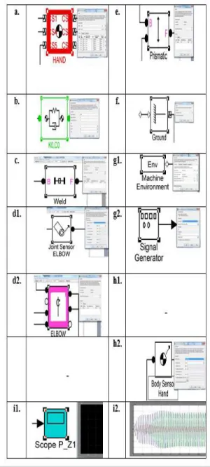
For this paper, it chose the Matlab simulation program (its Simulink), because this presents a friendly interface and, more importantly, has blocks (Table 3) that display the mechanical point of view for the system masses Mass Block
(a.), the mechanical characteristics (Elastic and Damping Block – b.), the connecting blocks that can copy the mechanical model in figure 1, respectively Weld Blocks (c.) and Cylindrical Joints (Joint elbow and Shoulder Block) d1. and
d2.). In other words, the connection between the blocks creates the same model as the theoretical model resulted from the mathematical modeling. Also, it can intervene in this system by imposing entry conditions that is z and the input frequency or pulse given by the Ground Block (f.), Machine Environment Block and Signal Generator (g1. and g2.).
Table 3
The main Simulink Blocks presented in the figures 1 and 2.
By accessing any of these blocks, a window opens in which it can input the mechanical theoretical model characteristics given by figure 1. Subsequently, this model will simulate the displacements of the system created by Anthropometrical parameters
m1 = 0.45
kg
=
' 3
l 0,298 m Jc3 = 0.0149 kgm2
m2 = 1.15
kg 3
l = 0.178 m
m3 = 1.9
kg
6 , 0 l /
l '
3 3 =
k0 = 155.8 x10³
N/m kt1 =
2Nm/rad
c0 = 30 Ns/m
k1 = 23.6 x10³
N/m
c1 = 202.8 Ns/m
k2 = 444.6 x10³
N/m
kt2 =
2Nm/rad
c2 = 500 Ns/m
k3 = 415.4 x10³
N/m
ct1 = 4,9
Nms/rad
c3 = 164.6 Ns/m
k4 = 50.25 x10³
N/m
c4 = 50 Ns/m
k’ = 2kd= 2 x
365.75 = 731.5 N/m
ct2=
6,14Nms/rad
c’ = 2cd = 2 x 58.5 =
Simulink. The Joint Actuator Block and Body Sensor Block (h1. and h2.) take over the displacements of the masses and convey it to the
Scope Block (i1. and i2.). This displays graphically the displacements of the center of these masses. Main displacement is imposed by the Prismatic Block (e.), which, in the case of this paper, is the z-axis that is along the hand-arm system. In this case, the selection of the “z” coordinates in the data window will be: x = 0; y = 0; z = 1.
The solutions obtained after integration equation of the figure 1 [4], they are the result of the integration of a differential equations system with the SimMechanics (Simulink) module using the 4th order Runge-Kutta method (ODE 45), and an integration period of 5s (figures 3, 4).
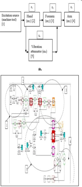
In the figures 1b, 2b the symbolized blocks, per ensemble, represent:
- Excitation source Block named [1]; Hand
(mass m1) Block named [2]; Forearm (mass m2)
Block named [3]; Arm (mass m3) Block named [4]; Mechanical vibration attenuator (md) Block named [5] (Fig. 2).
Like a short description of the simuling scheme: ensemble 1 contains in SimMechanics the blocks Env and Ground specific for the source of excitation (machine-tool), and the
Signal block where it is imposed at simulation the frequency or the excitation pulsation. We studied the excitation for two cases, one of 250 RPM and the other for 1000 RPM. The source of excitation is considered for this model is at a
rotation of 250 rpm – rotations per minute (f = 4.16 Hz) (Fig.3), and respectively at the
rotation of 1000rpm (f = 16.66 Hz) (Fig.4), similar to the theoretical model studied at the mechanical model presented in the figure 3.
The ensembles noted 2, 3, and 4 in the figures 1a, 2a are connected between each other by
Prismatic Blocks, blocks that impose the direction of the vibration’s transmission, by axis Ozh.
Equally, ensembles 1, 2, 3, and 4 are connected between each other by Spring and Damper Blocks, representing the blocks where the mechanical characteristic are introduced (rigidity and dampness coefficients) of the hand-arm system, according to Table 2.
Ensembles 2, 3, and 4, and subsequently for the vibration attenuator device ensemble 5 (Fig. 1a and Fig. 2a), comply with the same
anthropometric properties from table 2, as in the mechanical model proposed by figure 1a, respectively the Body Blocks with the masses m1, m2, m3 and subsequently m4 for the vibration attenuator device.
The Body Sensor and Scope Blocks are necessary for the visualization of individual solutions, on the anatomic elements: hand, forearm and arm, respectively the visualization of solutions (linear and angular displacements) of the system, obtained in SimMechanics.
In the study of the block scheme, the simplifying conditions imposed by the mechanical model in figure 1 were complied with, so it was considered the rotation in the shoulder joint of 0°, and in SimMechanics this was represented by Weld and Ground Blocks of ensemble 4 (Fig.1b), and of ensemble 5 (Fig.2b).
Fig. 1
a. The schematic model, per ensemble, of the hand-arm system;
The results obtained, in SimMechanics, were processed and overtaken in Excel, they analyzed comparatively regarding the two cases studied, respectively the hand-arm system without montage of the vibration attenuator device and
with the it mounted on the forearm (Fig.3, Fig.4).
a.
b.
Fig. 2a. The schematic ensemble model of the hand-arm system;
b. The scheme model of the mechanical model representing the hand-arm system, having mounted along the forearm the vibration attenuator developed in SimMechanics.
3. ANALYSIS REGARDING THE
SIMULATION OF THE HAND-ARM SYSTEM, WITHOUT OR WITH THE VIBRATION ATTENUATOR DEVICE
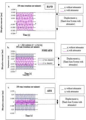
In the figures 1a and 2a analysing, it can be observed the movement of the hand (z1 displacement) for the rotation of the machine-tool of 250rpm, is not influenced by montage of the vibration attenuator device along the forearm (Fig.3a) or it is very slightly influenced by this, at the rotation of 1000rpm (Fig.4a). This behaviour might be due to the fact, that the vibration attenuator device is mounted after the joint, this only influencing the transmission of the vibrations from the joint up the forearm and the arm. The z1 displacement takes a maximal value of the graphic (Fig.3a) around 0.003 m.
Graphically, it can be observed that the vibrations transmitted from the source of excitation (machine-tool) are reduced, in case a mechanic vibration attenuator device mounted on the forearm in used. This displacement is noted in the paper with z3, and it is graphically represented in figures 3c and 4c.
In the figures 3b and 4b, it can be observed the minimization of the transmission of the vibrations for the forearm and the arm, when a vibration attenuator device is mounted along the forearm is used (z2). The values of the z2 displacements for the forearm are minimized from 0.003m till 0.002m (Fig. 3b.) (the revolution of 250rpm) and from 0.0025m till 0.0008m (Fig. 4b) (the revolution of 1000rpm).
To these graphics minimization (reduction) of the displacements, it varies from 0.001m till 0.0025m (n = 250 rpm) (Fig. 3c) and from 0.01m till 0.00025m (n = 1000rpm) presented in the figure 4c.
Due to the fact, that in the figures 4, comparatively with figures 3, the excitation at the entrance in the hand-arm system is 4 times bigger (from 250rpm till 1000rpm), for the same integration period (5s), and the frequency of graphical representations of the displacements harmonics are of four times bigger.
Fig. 3 Transmission of the vibration along the hand-arm system, using a vibration attenuator device (250rpm). a. Displacement of the hand- z1 [m];
b. Displacement of the forearm- z2 [m];
c. Displacement of the arm - z3 [m].
4. CONCLUSIONS
Thepurpose of the paper was to demonstrate that, the mechanical vibrations transmitted from an excitation source (ex. Machine-Tool) to the human operator (hand-arm system) are reduced from the hand to the elbow joint by mounting an attenuator device along the forearm [3], [4], [7], [8]. All these studies were done in order to avoid or reduce the action of the vibrations on the human body (in this case the hand-arm system) at the workplace, and respectively the reduction of their effect and the prevention of occupational illnesses [1], [2]. The introduction of this paper mentions that, the occupational illnesses occur after years of vibration exposure purpose of the paper to be reached, it developed a simulated model of a hand-arm system that would coincide as much as possible with a real one and it solved the equations of the simulated model., at the workplace.
Fig. 4 Transmission of the vibration along the hand-arm system, using a vibration attenuator device (1000rpm). a . Displacement of the hand- z1 [m];
b. Displacement of the forearm- z2 [m];
c. Displacement of the arm - z3 [m].
In order, for the simulation demonstrated that there is a way to reduce the mechanical vibrations for the hand-arm system model chosen. This could lead to the reduction of occupational illnesses that are frequently found in workplaces like this.
The conclusions of the paper validated the results generated by the simulation and have shown that, by using an attenuator device mounted parallel to the forearm (between the wrist and the elbow), we can reduce vibrations along the arm to the shoulder by 50%.
Remember it that it is a system of dynamic differential equations, so solved it using order 4 Runge-Kutta (ODE45) of the Matlab program. Also, it could not solve the equations in the lack of the anthropometric input data (mass, length, etc.) and the rigidity and dampness coefficients (k, c). It accomplished all this by means of three major steps:
mounted on the forearm), that is created according to the theoretical model.
The mini-dampers were purchased and mounted on the device and it tried to maintain the same technical characteristics as the theoretical model given by figure 2b. Such as, the displacements of the anatomical parts are of few millimeters, they are graphical results.
5. REFERENCES
[1] Detesan, Ovidiu-Aurelian, Cad model of the
RTTRR modular small-sized serial robot,
Acta Technica Napocensis series-Applied Mathematics Mechanics and Engineering, volume: 60 issue: 1 pages: 69-74 published:, issn: 1221-5872, 2017.
[2] Detesan, Ovidiu-Aurelian, The path
planning of rttrr small-sized industrial robot in a process of microprocessor packing, Acta
Technica Napocensis Series-Applied
Mathematics Mechanics And
Engineering, volume: 60 issue: 4 pages: 551-556 published: nov, accession number: wos:000428901100016
issn: 1221-5872, 2017.
[3] Detesan, Ovidiu-Aurelian, Workspace
determination for the RTTRR modular small-Robot, Acta Technica Napocensis
Series-Applied Mathematics Mechanics And
Engineering, volume: 60 issue: 1 pages: 551-556 published: nov, accession number: wos:000428901100016, issn: 1221-5872, 2017.
[4] Antal, Tiberiu Alexandru. Arduino Leonardo programming under windows, in java, from Jdeveloper using Ardulink. Acta Technica Napocensis - Series: Applied Mathematics, Mechanics, And Engineering, [s.l.], v. 60, n. 1, mar. 2017. issn 1221-5872. available at: <http://www.atna-mam.utcluj.ro/index.php /acta/article/view/825>. date accessed: 15 feb. 2018.
[5] Antal, Tiberiu Alexandru. Raspebrry PI 3 programming, in Java, using Blue J and Jdeveloper based on pi4j. Acta Technica Napocensis - Series: Applied Mathematics, Mechanics, And Engineering, [s.l.], v. 60, n. 1, mar. 2017. issn 1221-5872. available at: <http://www.atna-mam.utcluj.ro/index.php /acta/article/view/826>. date accessed: 15 feb. 2018.
[6] Antal, Tiberiu Alexandru; Chelaru, Julieta Daniela. A Multithreaded Java Client-Server Model For Robot Interaction. Acta Technica Napocensis - Series: Applied Mathematics, Mechanics, And Engineering, [s.l.], v. 60, n. 3, sep. 2017. issn 1221-5872. available at: <http://www.atna-mam.utcluj.ro/index.php/a cta/article/view/897>.date accessed: 15 feb. 2018.
[7] M. J. Griffin: Hand-transmitted Vibration:
Occupational Exposures and their Health Effects in Great Britain, University of Southampton, U.K, (2017), p. 218-228.
[8] SREN 5349-2:2003: Mechanical
Vibrations.Measurements and evaluation of human exposure at vibrations transmitted of hand.
SIMULAREA TRANSMISIBILITATII VIBRAȚIILOR LA SISTEMUL MANA-BRAȚ
CÂND ESTE UTILIZAT UN SISTEM DE ATENUARE AL VIBRAȚIILOR
Abstract. Scopul lucrării este de a demonstra reducerea vibrațiilor mecanice care se transmit la brațul operatorului, la locul de muncă. Acest lucru se poate face folosind un dispozitiv de atenuare, un amortizor montat paralel cu antebrațul, între încheietura mâinii și cot. Idea noua a acestei lucrări este studierea posibilității de simulare a acestui model cu / fără dispozitiv de atenuare a vibrațiilor, attenuator care va fi montat de-a lungul antebrațului.
Aurora FeliciaCRISTEA, Assistant Proffesor PhD Engineer, Technical University of Cluj-Napoca,