1
Mathematical and Software Engineering, Vol. 2, No. 1 (2016), 1-8 Varεpsilon Ltd, http://varepsilon.com
Comparative Analysis of the ITU Multipath Fade
Depth Models for Microwave Link Design in the
C, Ku, and Ka-Bands
Simeon Ozuomba
1*, Constance Kalu
2,
Akaninyene B. Obot
31,2,3
Department of Electrical/Electronic and Computer Engineering, University of Uyo, AkwaIbom, Nigeria
1
[email protected], [email protected], [email protected]
*Corresponding Author: [email protected]
Abstract
In this paper, the effects of various wireless network link parameters on the multipath fade depth are presented. The link parameters considered are frequency, path inclination, path length, terrain roughness index and the percentage of time fade depth is exceeded in the average worst month. The computation of the fade depth is based on two ITU models; ITU-R P.530-11 standard for quick planning applications and ITU-R P.530-11 standard for detailed link design. According to the results, ITU-R P.530-11 standard for quick planning applications overestimated the multipath fade depth when compared with the estimates from the ITU-R P.530-11 standard for detailed link design. Furthermore, the smooth terrains presented higher multipath fade depth than the rough terrain. Also, multipath fade depth increases with increasing frequency and path length, but decreases with increasing path inclination, terrain roughness index and the percentage of time the fade depth can be exceeded.
Keywords: Path Inclination , Path length, Terrain roughness index, Multipath Fade
depth, C-Band , Ku-Band, Ka-Band, Wireless Network.
1. Introduction
Wireless communication channels are in most cases characterized by multipath fading environments. Multipath is a situation in wireless communication system whereby radio signals reaching the receiving antenna arrive from two or more paths. The things that do cause multipath include reflections from terrestrial objects for example buildings and mountains, reflection from water bodies, atmospheric ducting, as well as ionospheric reflection and refraction [1, 2, 3]. Multipath may lead to interference, which can be either constructive or destructive. Also, multipath can cause phase shifting of the signal. On the other hand, fading can be described as rapid fluctuations of signal amplitudes or phases, as well as, multipath delays of a wireless signal over a short period or short distance [1, 4].
2
ITU provided models for predicting multipath fading on terrestrial line-of-sight (LOS) links. Specifically, ITU recommendation, ITU-R P.530 provides multipath fading prediction model based on fading measurements of 251 links in various geoclimatic regions [10, 11, 12]. Rec. ITU-R P.530 recommendation is used for the prediction of path loss for microwave links, as well as, for the prediction of link availability in the average worst month for such links [12, 13]. In respect of Rec. ITU-R P.530, the parameter needed to calculate the link availability of terrestrial line-of-sight links includes climatic parameters, terrain roughness index and geoclimatic factor [12, 13]. In Rec. ITU-R P.530, ITU provided two approached to compute the geoclimatic factor. Each of the two approaches is associated with a model for predicting link outage probability due to multipath fading [12, 13].
In this paper, the effects of various wireless network link parameters on multipath fade depth are presented. The link parameters considered are frequency, the path inclination, and path length, terrain roughness index and the percentage of time fade depth is exceeded in the average worst month. The computation of the fade depth is based on two ITU models; ITU-R P.530-11 standard for quick planning applications and ITU-R P.530-11 standard for detailed link design.
2 Theoretical Background
2.1 Multipath Fade Depth Computation Based on ITU-R
P.530-11 Standard For Detailed Link Design
According to detailed link design given in ITU-R P.530-11 standard , the percentage of time that multipath fade depth (dB) is exceeded in the average worst month
can be calculated by [14, 15,16] as:
= . 1 + . 10 . . !" # % (1) where
Pw is the percentage of time that fade depth (A) is exceeded in the average worst month
f is the frequency (GHz)
ℎ& is the lower antenna altitude (i.e. the smaller of transmitter antenna height ('() and receiver antenna height ('+) ) both in meters) [5].
d is the path length (km) and
is the path inclination (in mrad), defined as ; = |-./ -0/ |
1 (2)
K denotes the geo-climatic factor (worst month) and for detailed link design in ITU-R P.530-11 standard K is given is given as [14, 15, 16]:
= 10 . . 123 45 .6 (3)
where
dN1 is the point refractivity gradient in the lowest 65 metre of the atmosphere not exceeded for 1% of an average year [5].
47 is the area terrain roughness index. Terrain roughness index is defined as the standard deviation of terrain heights (m) within a 110km x 110km area [10,11,13]. By rearranging equation (1) the multipath fade depth (A) can be computed as follows;
0.032: − 0.0085ℎ&−3> = log B E 1F.G 3H ICD
3 >
3 = 0.032: − 0.0085ℎ&− log B E 1F.G 3H ICD J K".LM N (5)
= 10 B0.032: − 0.0085ℎ&− log B E 1F.G 3H ICD J K".LM NN (6)
2.2 Multipath Fade Depth Computation Based on ITU-R
P.530-11 Standard For Quick Planning Applications
According to ITU-R P.530-11 standard for quick planning applications, the percentage of time PP that multipath fade depth (dB) is exceeded in the average worst month
can be calculated by [14, 15, 16, 17]:
= . 1 + 3. 10 . . 3 !" # % (7) = |-./ -0/ |
1 (8)
K denotes the geo-climatic factor (worst month) and for quick planning applications in ITU-R P.530-11 standard K is given is given as [14, 15,16,17]:
= 10 6. . 123 (9)
By rearranging eq. (7), the estimated multipath fade depth can be computed as follows: 0.033: − 0.001ℎ&−3> = log B E 1F." 3H ICD
J K!.G N (10)
>
3 = 0.033: − 0.001ℎ&− log B
CD
E 1F." 3H IJ K!.G N (11)
= 10 B0.033: − 0.001ℎ&− log B E 1F." 3H ICD
J K!.G N N (12)
3 Methodologies
In this paper, analytical expressions for multipath fade depth based on two different ITU models are examined in respect of the effect of the following key parameters; (i) Frequency (f) (ii) the path inclination ( ) (iii) path length (d) (iv) terrain roughness index (Sa) (v) the percentage of time (Pw) that fade depth is exceeded in the average worst month. The multipath fade depth that can be experienced in the link is computed using two different ITU models, namely; (i) ITU model 1 which is ITU-R P.530-11 standard for detailed link design. The model involves the use of terrain roughness index (ii) ITU model 2 which is ITU-R P.530-11 standard for quick planning applications. The model does not involve the use of terrain roughness index. Multipath fade depth is computed with equation (6) for detailed link design model and with equation (12) for quick planning applications model.
4
Similar approach is used to compute the multipath fade depth for various values of terrain roughness index, while the other parameters are kept constant.
As regards path inclination ( ) given in equation (8), when '() = '+) QℎRS = 0. In this paper, d is kept constant and is varied from zero to a maximum value selected in the paper to show the effect of path inclination on the two ITU models for multipath fading. In addition, in order to show the effect of path length (d) on the two ITU models for multipath fading, the path inclination is kept constant while d is varied. In this paper, the terrain roughness index, Sa ranges from 20 feet (considered as smooth terrain) to 140 feet (considered as rough terrain).
4 Results and Discussion
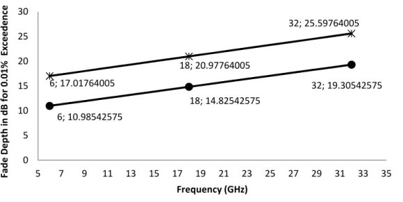
For the multipath fade depth computation in Figure 1, Path length (d ) =10 km; Transmitter antenna height ( '() = 105m; Receive antenna height ('+) )) = 95m,
Path Inclination ( ) = 1mrad, Terrain Roughness Index (47) =50 feet (or ≈ 15URQRVW); Point Refractivity Gradient (dN1) = - 400 and the frequencies are 6Ghz, 18GHz and 32GHz. According to Figure 1, with the given frequencies and terrain roughness index of 6m (or 20 feet) the ITU-R P.530-11 standard for quick planning applications overestimated the multipath fade depth when compared with the estimates from the ITU-R P.530-11 standard for detailed link design. Also, the multipath fade depth increases with frequency.
6; 10.98542575
18; 14.82542575
32; 19.30542575 6; 17.01764005
18; 20.97764005
32; 25.59764005
0 5 10 15 20 25 30
5 7 9 11 13 15 17 19 21 23 25 27 29 31 33 35
F
ad
e
D
e
p
th
i
n
d
B
f
o
r
0
.0
1
%
E
x
ce
e
d
e
n
ce
Frequency (GHz)
Figure 1 Effect of frequency on Multipath Fading (dB) using (i) ITU-R P.530-11 standard for detailed link design (ii) the ITU-R P.530-11 standard for quick planning applications (where Percentage of the
Multipath Fading Time Exceeded is 0.01% )
Multipath Fading (dB) ITU-R P.530-11 standard for detailed link design
5
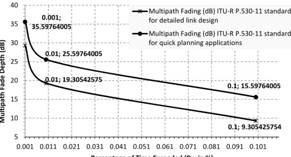
However, in Figure 2, the multipath fade depth decreases with increasing (Pw) percentage of time the fade depth can be exceeded. In both ITU models, the fade depth was highest at Pw = 0.001% and least at Pw = 0.1%. Again, in Figure 2, for the three values of Pw considered, the ITU-R P.530-11 standard for quick planning applications overestimated the multipath fade depth when compared with the estimates from the ITU-R P.530-11 standard for detailed link design.
0.01; 19.30542575
0.1; 9.305425754 0.001;
35.59764005
0.01; 25.59764005
0.1; 15.59764005
5 10 15 20 25 30 35 40
0.001 0.011 0.021 0.031 0.041 0.051 0.061 0.071 0.081 0.091 0.101
M
u
lt
ip
at
h
F
ad
e
D
e
p
th
(
d
B
)
Percentage of Time Exceeded (Pw in %)
Figure 2 Effect of (Pw) Percentage of Time the Multipath Fading is Exceeded on Multipath Fading (dB) using (i) ITU-R P.530-11 standard for
detailed link design (ii) the ITU-R P.530-11 standard for quick planning applications (where Frequency is 32GHz
Multipath Fading (dB) ITU-R P.530-11 standard for detailed link design
Multipath Fading (dB) ITU-R P.530-11 standard for quick planning applications
6; 20.97677379
24; 18.44812183
42; 17.42736202
6; 25.59764005 24; 25.59764005 42; 25.59764005
15 17 19 21 23 25 27
4 6 8 10 12 14 16 18 20 22 24 26 28 30 32 34 36 38 40 42 44
M
u
lt
ip
at
h
F
ad
e
D
e
p
th
i
n
d
B
Terrain Roughness Index (Sa) in Meters
Figure 3 Effect of Terrain roughness Index (Sa) on Multipath Fading (dB) using (i) U-R P.530-11 standard for detailed link design (ii) the ITU-R P.530-11 standard
for quick planning applications (where Frequency is 32GHz and Pw = -0.01%)
6
According to experts, terrain roughness index of 20 feet (or 6 meters) is considered smooth terrain whereas the terrain with terrain roughness index of 140 feet (or 42 meters) is considered very rough terrain. Consequently, in Figure 3 multipath fade depth is higher for smooth terrain than for rough terrain. Essentially, as the terrain roughness increases, the multipath fade depth decreases. In all, within the range of values for terrain roughness index of 140 feet (or 42 meters) to 20 feet (or 6 meters), the ITU-R P.530-11 standard for quick planning applications overestimated the multipath fade depth when compared with the estimates from the ITU-R P.530-11 standard for detailed link design.
In Figure 4, the effect of path inclination on the multipath fade depth is presented. Precisely, Figure 4 shows that the multipath fade depth is highest when the path inclination is zero (0) and as the path inclination increases, the multipath fade depth decreases.
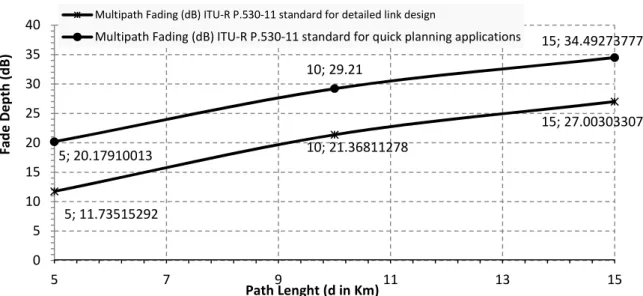
In Figure 5, the effect of path length on the multipath fade depth is presented. According to Figure 5 the multipath fade depth is increases with increase in path length.
0; 21.36811278 1; 18.44812183 2; 16.74003661 0; 29.21 1; 25.59764005 2; 23.48454494 15 17 19 21 23 25 27 29
0 1 2
M u lt ip at h F ad e D e p th ( d B )
Path Inclination (ɛp)
Figure 4 Effect of Path Inclination (ɛp) on Multipath Fading (dB) using (i) U-R P.530-11 standard for detailed link design (ii) the ITU-R P.530-11 standard for
quick planning applications (where Frequency is 32GHz and Pw = 0.01%) Multipath Fading (dB) ITU-R P.530-11 standard for detailed link design Multipath Fading (dB) ITU-R P.530-11 standard for quick planning applications
5; 11.73515292 10; 21.36811278 15; 27.00303307 5; 20.17910013 10; 29.21 15; 34.49273777 0 5 10 15 20 25 30 35 40
5 7 9 11 13 15
F ad e D e p th ( d B )
Path Lenght (d in Km)
Figure 5 Effect of Path Length on Multipath Fading (dB) using (i) U-R P.530-11 standard for detailed link design (ii) the ITU-R P.530-11 standard for quick planning applications
(where Frequency is 32GHz and Pw = 0.01%)
Multipath Fading (dB) ITU-R P.530-11 standard for detailed link design
7
From the overall results, it can be stated that the ITU-R P.530-11 standard for quick planning applications overestimated the multipath fade depth when compared with the estimates from the ITU-R P.530-11 standard for detailed link design. Furthermore, the smooth terrains present higher multipath fade depth than the rough terrain. Also, multipath fade depth increases with increasing frequency and path length, but decreases with increasing path inclination, terrain roughness index and the percentage of time the fade depth can be exceeded. The results are useful as they will help microwave link designers to know how to adjust the various microwave link parameters so that they can satisfy the desired design specifications.
5 Conclusions
The effects of various microwave link parameters on the multipath fade depth are presented. The computation of the multipath fade depth is based on two ITU models, namely; the ITU-R P.530-11 standard for quick planning applications and the ITU-R P.530-11 standard for detailed link design. In all, the ITU-R P.530-11 standard for quick planning applications overestimated the multipath fade depth when compared with the estimates from the ITU-R P.530-11 standard for detailed link design. The findings in this paper are useful as they will help wireless network designers to know how to adjust the various link parameters so that they can satisfy the desired design specifications.
References
[1] Mitra, A. (2009). Lecture notes on mobile communication; Chapter 5 Multipath Wave Propagation and Fading. A Curriculum Development Cell project Under
QIP, IIT Guwahati. Available at
http://www.iitg.ernet.in/scifac/qip/public_html/cd_cell/EC632.pdf
[2] Gupta, R. S., & Sarma, K. K. (2013). Split MLSE Adaptive Equalization in Severely Faded Rayleigh MIMO Channels. International Journal of Electronics
Signals and systems (IJESS), 3(1), 87-91.
[3] Kumar, P. S., & Bhaskar, P. R. (2013). Optimized Behaviour of MIMO System under Different Equalization Techniques and Modulation Schemes over Rayleigh and Rician Fading Channels. International Journal of Scientific Engineering and
Technology, Volume No.2, Issue No.9, pp : 830-834.
[4] Kharel, M. B., & Shakya, S. R. (2014). Simulation on Effect of Doppler shift in Fading channel and Imperfect Channel Estimation for OFDM in Wireless Communication. In Proceedings of IOE Graduate Conference (p. 537).
[5] Mohajer, M., Khosravi, R. and Khabiri, M. (2006, May). Flat Fading Modeling in Fixed Microwave Radio Links Based on ITU-R P. 530-11. In Microwaves, Radar
& Wireless Communications, 2006. MIKON 2006. International Conference on
(pp. 423-426). IEEE.
[6] Prabhu, G. S., & Shankar, P. M. (2002). Simulation of flat fading using MATLAB for classroom instruction. Education, IEEE Transactions on, 45(1), 19-25.
[7] Rappaport, T. S. (1996). Wireless communications: principles and practice (Vol. 2). New Jersey: Prentice Hall PTR.
[8] Purkayastha, B. B., & Sarma, K. K. (2015). A digital phase locked loop based
signal and symbol recovery system for wireless channel. Springer India.
[9] Mandayam, N. (2002). Wireless communication technologies. Lecture notes. [10] Agba, B. L., Ben-Sik-Ali, O., Morin, R., & Bergeron, G. (2011). Recent Evolution
of ITU Method for Prediction of Multipath Fading on Terrestrial Microwave Links.
8
[11] Göktas, P. (2015). Analysis and implementation of prediction models for the design
of fixed terrestrial point-to-point systems (Doctoral dissertation, bilkent university).
[12] ITU (2013) Propagation data and prediction methods required for the design of terrestrial line-of-sight systems," International Telecommunication Union
Recommendation ITU-R P. 530-15, 2013.
[13] Goktas, P., Altvntas, A., Topcu, S., & Karasan, E. (2014, August). The effect of terrain roughness in the microwave line-of-sight multipath fading estimation based on Rec. ITU-R P. 530-15. In General Assembly and Scientific Symposium (URSI
GASS), 2014 XXXIth URSI (pp. 1-4). IEEE.
[14] Ugwu, E. B. I., Umeh, M. C. and Ugonabo, O. J. (2015). Microwave propagation attenuation due to earth’s atmosphere at very high frequency (VHF) and ultra-high frequency (UHF) bands in Nsukka under a clear air condition. International
Journal of Physical Sciences, 10(11), 359-363.
[15] ITU (2001) Propagation data and prediction methods required for the design of terrestrial line-of-sight systems," International Telecommunications Union,
Geneva, Recommendation of ITU-R P.530-09, February 2001.
[16] Asiyo, M. O. (2013). Characterization and Modelling of Effects of Clear Air on
Multipath Fading in Terrestrial Links (Doctoral dissertation, University of
KwaZulu-Natal, Durban).
[17] Odedina, P. K., & Afullo, T. J. (2008). Estimation of Secondary RadioclimaticVariables and its Application to Terrestrial LOS link Design in Southern Africa, Proceedings of IEEE AFRICON Conference 2008, Wild Coast
Sun, South Africa, September 7 -10, 2008.