Modeling and Analysis of the Dynamic Performance of
a Gird Connected Micro Hydro Power Plant Deploying
Synchronous Generator
Waqas Ali*, Haroon Farooq
Dept. of Electrical Engineering (RCET), University of Engineering and Technology, Lahore, Pakistan * Corresponding Author: Email: [email protected]
Abstract
This paper discusses the dynamic behavior of a Micro Hydro Power Plant (MHPP) deploying synchronous generator in grid connected operation. The investigation is carried out through dynamic modeling and simulation of the proposed system considering different operational conditions using MATLAB/Simulink. The results are evaluated to assess the dynamic performance of the proposed system from regulation standpoint considering various synchronous generator parameters such as terminal voltage, field voltage, rotor speed, stator current, speed deviation, input mechanical power, output electrical power and output frequency under transient and steady states at different loads. The study reveals that the system stability improves if the system is operated at full load because as the load increases, the time required by the generator parameters to reach the steady state decreases but the fault current increased. Furthermore, it is also concluded that the regulation times increase with the decrease in the power factor. Therefore, appropriate protection schemes, to cater for increased fault current at full load, and power factor compensation must be provided to ensure the system stability.
Key Words:
Micro Hydro Power Plant (MHPP), Grid Connected, Regulation, Modeling, Simulation1.
Introduction
Hydro power, satisfying the 20% of world power needs and representing the 94% production of renewable energy, is a highly attractive and widespread source of alternate energy [1]. This is due to the fact that several large hydro electric power stations capable of producing huge amounts of power were set up during the last century. Owing to rareness of high capacity reservoirs and several environmental sustainability issues, it is not viable anymore to build large hydropower stations. In contrast, Micro Hydro Power Plants (MHPPs) are not only environment friendly but also run of river plants which mostly do not need any water reservoir and can operate with even a small flow of water [2, 3].
Generally, majority of the MHPPs operate in standalone mode to supply the electrical power to local remote area loads [4] where the population is not very large and distributed sparingly and the expansion of grid system is not economically practicable because of large huge investment required for transmission network. However, in recent years, a rising interest on grid connection of MHPPs have emerged, mainly because they are a proven technology with very good performance and low investment costs when compared particularly to solar and wind based renewable technologies [2, 3, 5, 6]. Moreover, the payback
period for grid connected micro hydro systems is reasonably low, normally 5 to 8 years [7]. Therefore, where the prospective sites are available adjacent to the distribution system, MHPPs can be designed to operate in connection with the local grid systems. The driving factors include the financial advantage of no fuel usage by hydro turbines, power capacity improvement to meet up the escalating demand and to keep the supply continue in the system [1].
The MHPPs can be installed either with induction generator or synchronous generator [5, 8, 9, 10]. The induction generators are less common but are increasingly being used in small schemes [9]. For both on-grid and off-grid modes induction generator gives advantages such as ruggedness, reduced size, reduced cost, ease of maintenance, absence of separate DC source, brush less (in squirrel cage construction) and self-protection against short circuits and severe overloads [1, 11, 12, 13, 14, 15, 16, 17]. But the biggest drawback of the induction generator is the lagging power factor because the machine is magnetized from the stator [18, 19], so as a result less power is available with a given current in contrast to synchronous machine [19]. The use of synchronous generator at low power generation is very rare due to its high price in comparison to the whole system expenditures, making its use economically undoable sometimes [20]. Despite
that, the MHPPs using synchronous generators can be considered highly optimal, because of the features associated with its high-tech control [1, 5, 20, 21]. Hence, the purpose of this study is to use synchronous generator for the development of MHPP, because of its burly technical advantages over induction generator in terms of voltage control and regulation [10, 20, 21]. Though, several studies have been conducted by researchers about the grid connection of renewable energy driven plants based on solely hydro or wind generation, or based on hydro/wind or hydro/solar hybrid generation [11, 16, 22, 23, 24, 25, 26, 27, 28, 29]. But, in all these studies, they used induction generator as a core component to drive hydro and/or wind technologies in their research because they are generally best suited for providing energy in grid connected mode [19]. However, many studies have also reported the poor voltage and/or frequency regulations of induction generator used for the development of
micro hydro systems [11, 20, 30, 31, 32, 33, 34, 35].
Therefore, the focus of the proposed work is to investigate the dynamic performance of a synchronous generator based MHPP operating in grid connected mode from regulation standpoint. The study is carried out considering different loads under transient and steady state conditions in low voltage system. This research work also presents the detailed modeling of the proposed system utilizing MATLAB/Simulink.
2.
Structure of MHPP
Fig. 1 portrays the usual composition of a typical MHPP. Hydro electric power plants work on the principle of transforming the potential (mass) and kinetic (flow) energy of water into mechanical energy to rotate the rotor of an electric generator [36]. The energy transformation phases
in a hydro electric power station are shown in Fig. 2.
Fig. 1: Composition of a typical MHPP
Power generation from the water depends upon the combination of head and flow which must be available to produce electricity [4]. Mathematically, hydraulic power available from a water source such as stream or river can be represented as:
hyd
P gQH (1)
Where: Phyd, ρ, g, Q and H represent the hydraulic power (watt), water density (1000 kg/m3), gravity (9.8 m/s2), effective flow rate (m3/s) and effective head (m) respectively.
Fig. 2: Energy transformation conversion phases The higher the flow or head higher will be the electricity produced. The produced electrical power will remain less than the input hydraulic (water) power because of system’s components inefficiencies. Thus, the final power (electrical) delivered to the system is mathematically expressed as:
F H
P P (2)
Where: PF = final electrical power, kW; η = system’s components overall efficiency; PH = hydraulic power (or Phyd), kW.
3.
System Diagram Under
Investigation
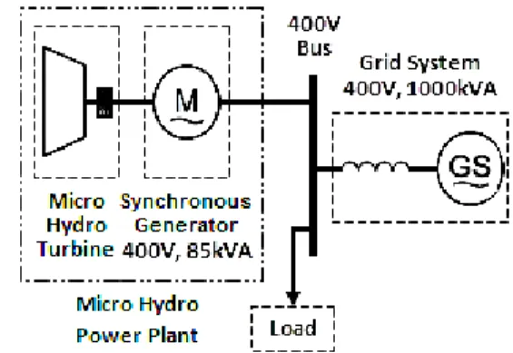
The schematic of the grid connected MHPP system is given in Fig. 3. A three phase 50 Hz, 400 V, 85 kVA, 1500 rpm synchronous generator is connected to the 50 Hz, 400 V, 1000 kVA utility grid. The output power of the synchronous generator is delivered to the utility grid and external load by means of 400V bus.
4.
System and its Components
Modeling
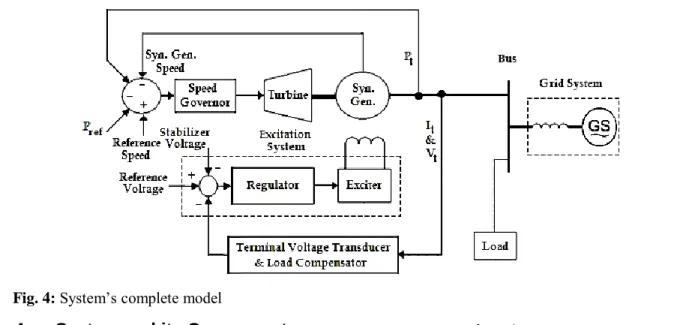
The detailed proposed system for modeling considered in this paper is demonstrated by Fig. 4. A variable speed micro hydro power turbine is driving the synchronous generator which is connected to grid system through a bus. In this model, the speed of micro hydro turbine is controlled by a speed governor and the control of the field voltage is facilitated by a regulator to ensure the smooth export of the power to grid system and load. The detailed mathematical representation of these components is as follow.
4.1 Turbine Modeling with Penstock
The non-linear turbine model with penstock assuming non-elastic water column is opted for the proposed micro hydro system [37]. Fig. 5 depicts this model, which is the combination of a single penstock and a hydraulic turbine. Mathematically, the model of a single penstock of length L and cross-sectional area A is represented as [37]:
1 1 l w dq
h h
dt T (3)
Where q, Tw, hl and h represent the flow rate of water, water time constant, head loss and head at the turbine admission in per unit form respectively. The water time constant is calculated as [37]:
base w
base Lq T
gAh
(4)
The hbase and qbase are the base head and base flow quantities in (4), while g represents the gravity. The reservoir head minus the tailrace head is considered as the base head and the flow rate through the turbine with fully gates open is taken as base flow rate [38].
The model of a hydraulic turbine is mathematically described as [37]:
m t nl
P A h qq DG (5) Where, the Pm represents the per unit mechanical
Fig. 4: System’s complete model
power which is not 100% efficient. Thus, the subtraction of net rated (q) and no load (qnl) flows is taken to account for turbine losses. The term DG∆ω is the speed deviation damping effect is also included to account for losses which is function of the G (gate opening) [37]. The At is the turbine gain and mathematically determined using full load (Gfl) and no load (Gnl) gate positions [39].
1 . t fl nl A G G
(6)
4.2
Synchronous Generator ModelingA synchronous machine is mathematically modeled by representing its electrical and mechanical properties. The machine’s electrical part is represented using d-q axis transformation in the rotor frame of reference. The voltage and flux equations for this reference frame are as follow [40].
Voltage equations:
d s d r q d
d v r i
dt
(7)
q s q r d q
d v r i
dt
(8)
'fd 'fd 'fd d 'fd
v r i
dt
(9)
'kd 'kd 'kd 'kd d
v r i
dt
(10)
1 1 1 1
'kq 'kq 'kq d 'kq
v r i
dt
(11)
2 2 2 2
'kq 'kq 'kq 'kq d
v r i
dt
(12)
Flux equations:
' '
d L id d Lmd i fd ikd
(13)
' 1 ' 2
q L iq q Lmq ikq i kq
(14)
'fd Lmd id i'kd i'fd L'lfd Lmd
(15)
'kd Lmd id i'fd i'kd L'lkd Lmd
(16)
1 2 1 1
'kq Lmq iq i'kq i'kq L'lkq Lmq
(17)
2 1 2 2
'kq Lmq iq i'kq i'kq L'lkq Lmq
(18)
Where: v, r, i, ω, φ and L from (7) to (18) represent the voltage, resistance, current, speed, flux linkage and inductance quantities respectively. The subscripts d, q, fd, s, r, md and mq in these quantities indicate the d axis, q axis, d axis field, stator, rotor, d axis magnetizing and q axis magnetizing components. While, the subscripts kd, kq1 and kq2 designate the d-q axis damper winding components. Whereas, the subscripts lkd, lkq1, lkq2 and lfd specify the d-q axis damper winding and d axis field winding leakage components respectively.
The mechanical part of the synchronous machine is mathematically expressed as follows [40] by using rotor speed (ωr), inertial co-efficient (J), mechanical (Tm) and electromagnetic (Te) torques, and co-efficient of friction (F).
1
( )
r
m e r
d
T T F
dt J
(19)
4.3 Speed Governor Modeling
Fig. 6 shows the mathematical model of electro-hydraulic type Proportional-Integral-Derivative (PID) speed governor adopted for the current work [41]. This is the modern type of governor which is flexible and gives better performance [37].
Different variables and parameters required for the given model are as follow: ωref = reference
speed; ωr = shaft/rotor speed; Pref = reference mechanical power in pu; Pt = terminal electrical power in pu; Kp, Ki, Kd = proportional, integral and derivative gains respectively; TA, TD, TC = time constants for pilot and gate servos, and gate closing time respectively; RP = permanent droop [37, 42].
The governor time constants such as TA, TD and TC are adjusted by the pressure/flow characteristics of the gate and its servos [42]. While, the PID controller gains Kp, Ki, and Kd are selected according to as [37].
1
0.625 w T
p
T R
K H
(20)
3.33 p
R w
i K
T T
K
(21)
3 p
d w
K
K T (22)
Where, the variable RT and TR in (20) and (21) represent the reset time and transient droop respectively.
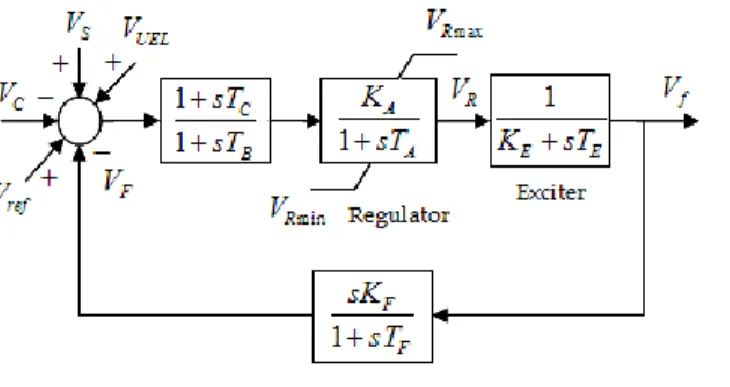
4.4 Excitation System Modeling
Fig. 7 shows the mathematical model of the DC excitation system used for this research work [43]. The voltage regulator and DC exciter are the basic elements of this model that form this excitation system.The parameters and the variables used in model of Fig. 7 are defined as follow: Vref = voltage regulator reference voltage; VS = power system stabilizing voltage; VC = output of terminal voltage transducer and load compensation elements; VF = excitation system stabilizer output voltage; VUEL = under excitation limiter output; TA, TB, TC = time constants for voltage regulator, TA is the major time constant while TB and TC are frequently small enough to be neglected; KA =
voltage regulator gain; VR, VRmin, VRmax = voltage
regulator output, minimum and maximum voltage regulator outputs respectively; KE = exciter constant related to self-excited field; TE = exciter time constant; Vf = exciter output voltage; TF = time constant for excitation control system stabilizer; KF = excitation control system stabilizer gain [43, 44].
Therefore, the exciter output voltage is related to regulator output voltage as:
R f
E E
V V
K sT
(23)
4.5 Terminal Voltage Transducer
and Load Compensator
Modeling
The principal input to the excitation system model is the output voltage VC from the synchronous machine terminal voltage transducer and load compensator model which are shown in Fig. 8. The parameters and the variables VT and IT in the model of Fig. 8 are the synchronous machine terminal voltage and current respectively. While, RC and XC represent the resistive and reactive component of load compensation respectively. Whereas, VC1 is the signal
proportional to compensated terminal voltage and TR is the regulator input filter time constant.
Fig. 8: Model of terminal voltage transducer and load compensator
4.6 Other Components Modeling
The given block-sets in SimPowerSystems library of the MATLAB/Simulink software package are deployed to perform the modeling of the remaining components (such as bus, load andgrid system) of the model of Fig. 4 as follow. The block-sets of “three-phase source”, “three-phase V-I measurement” and “three-phase parallel RLC load” from the sources, measurements and the elements sub-libraries respectively are used to model the grid, bus and load correspondingly.
5.
Simulation Results and
Discussions
The proposed system of grid connected MHPP deployed synchronous generator is simulated in MATLAB/Simulink as follow. The
models for some of the components such as hydraulic turbine, synchronous generator, speed governor, excitation system, and terminal voltage transducer and load compensator are developed using Simulink basic block-set library. While; for grid, bus and load modeling, the existing built in block-sets in the SimPowerSystems library are used. The proposed system model is simulated to assess and analyze the dynamic performance of the synchronous generator based MHPP from regulation point of view under transient and steady states at different loads; i.e. 50% loading, 75% loading and at full or 100% loading; considering
different Power Factors (PF); i.e. unity, 0.9 and 0.8; in the grid connected operation. For the transient conditions, the system is simulated for 10 to 12 sec and at 3.1 sec a disturbance is created on the 400 V bus for 0.1 sec by a three-phase to ground fault. The simulation results depict the waveforms for synchronous generator terminal voltage (Va), field voltage (Vf), rotor speed (w),
three phase stator current (Iabc), rotor speed
deviation (dw), generator input mechanical power
(Pm), generated electrical output power (Peo) and
output frequency (f).
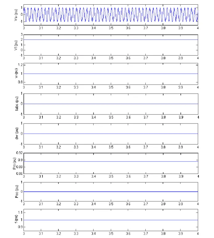
Fig. 9 depicts the simulation results at no load where the waveforms are shown between 3 to 4 sec only on time scale for better view and simplicity. Under steady state at no load, the pu value of the terminal voltage, field voltage, rotor speed, stator current, speed deviation, mechanical power, output electrical power and output frequency are 1.0, 2.1, 1.0, 0.0, 0.0, 0.895, 0.0, 1.0 pu respectively.
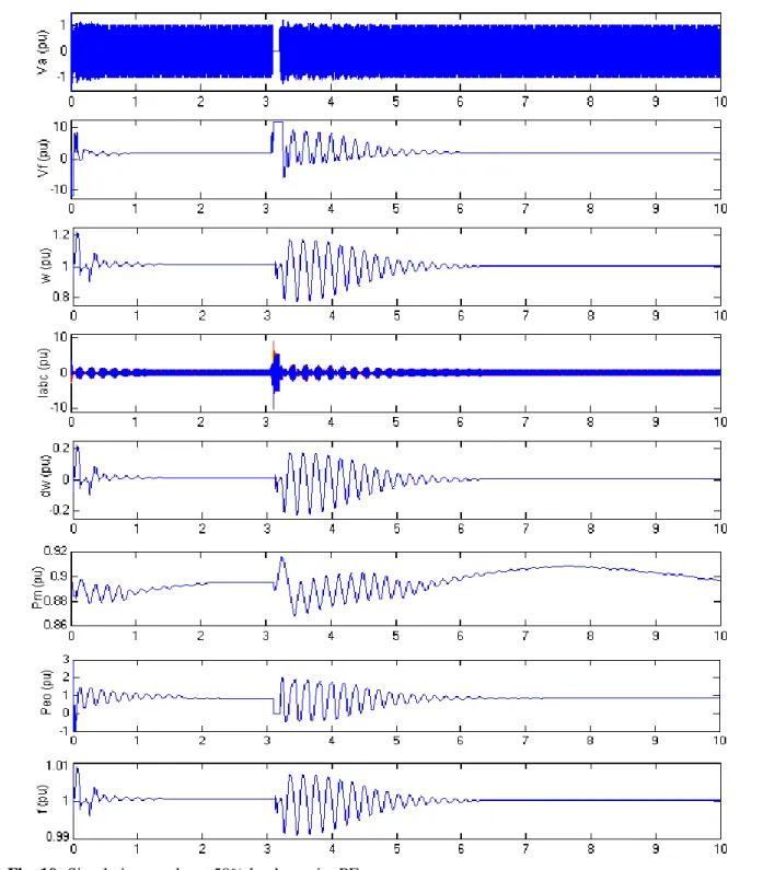
Fig. 10 shows the simulation results at 50% loading at unity PF where the terminal voltage is varying at the start of the simulation. At the
occurrence of fault i.e. transient state, it drops to 0 pu before restoration to nominal value rapidly following the clearance of the fault. The rapid restoration of the terminal voltage is because of the output voltage of excitation system that goes to a high value of 11.5 pu during the fault. On the occurrence of fault, the machine speed drops to the value of about 0.8 pu, then it swings around 1.0 pu as the speed governing system normalizes it. However, during transient, the stator current rises very high up to 9 pu. The rotor speed deviates up
to about 0.2 pu and then oscillates around 0 pu before the fault is cleared. The mechanical power takes a rise of 0.915 pu during fault, then falls and fluctuates before returning to its steady state value. The output generated electrical power falls to 0 pu during fault and varies across its nominal value of 0.895 pu before becoming stable. The output frequency shows the analogous behavior of rotor speed, it is dropped to about 0.99 pu on occurrence of fault, then oscillates around 1 pu before the fault clearing.
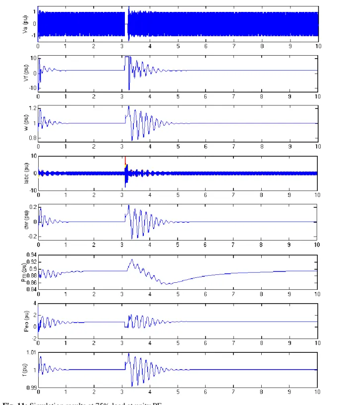
At unity PF loading of 75%, Fig. 11 demonstrates that the terminal voltage is varying in the start which drops to 0 pu at the occurrence of the fault and comes back to steady state rapidly after the fault is cleared. While, during the fault, field voltage goes to the high value of 11.5 pu same as to 50% loading case. The generator speed reaches about 1.22 pu on fault occurrence, then it alternates just about 1 pu to become regulated. However, the stator current reached up to 10 pu during the fault which is higher than the
magnitude value in 50% loading case. The rotor speed deviation approaches to 0.22 pu during fault and then oscillates around 0 pu until fault clearing. Whereas the mechanical power takes a rise of maximum 0.93 pu during fault and then falls to about 0.86 pu before reaching the steady state. The output power falls to 0 pu during fault and varies around its nominal value before becoming stable same as in 50% loading case. The output frequency shows the analogous behavior of rotor speed, it reaches to the magnitude of about 1.009
pu on occurring of fault, then oscillates around 1 pu until the fault clearing identical to the 50% loading case.
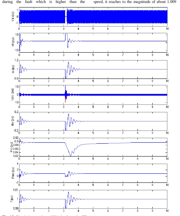
The Fig. 12 shows the results for full or 100% loading case at unity PF. The terminal voltage falls down to 0 pu in transient state and quickly returns to its steady state value as the fault is cleared. On fault, the field voltage reaches to 11.5 pu value similar to 50% and 75% loading cases. The machine’s speed drops to the value of 0.8 pu on fault occurrence, then it alters about 1 pu to become regulated. However, the stator current shows a high-rise in its value during transient about 12 pu which is higher than the value in 50% and 75% loading cases. The rotor speed deviation approaches to -0.2 pu and then oscillates around 0 pu before fault clearing. The mechanical power takes a dip of 0.82 pu on the occurrence of fault and then varies increasingly to reach toward its steady state value. The generated electrical power falls to 0 pu during fault and varies around its nominal value before stabilizing. The output frequency shows the behavior analogous to the rotor speed as it falls to about 0.99 pu during transient, then vacillates around 1 pu before the fault clearing alike to 50% and 75% loading cases.
Fig. 10, Fig. 11 and Fig. 12 also reveal that the field voltage, rotor speed, stator current, speed deviation, mechanical power, output power and output frequency take much longer than the terminal voltage to stabilize. The recovery time for various simulation scenarios are summarized in the Table 1 which show that the recovery time deceases with the increase in the loading. However, the magnitude of the fault current also increases with the increase in the load as already discussed. The results in Table 1 also depict the fact that regulation time increases with the decrease in the Power Factor (PF).
As the magnitude of fault current increases with the increased load, appropriate protection must be provided. In the grid connected micro hydro system, the application of overcurrent protection scheme is the simple way to tackle the fault current resulted from short circuits or ground faults [45]. Usually the fault current also known as overcurrent is significantly higher than the normal (rated) load current and is used as basic precondition for the operation of overcurrent protection scheme that is accomplished by the combination and coordination of sensing devices, protective relays and current interrupting devices [46].
Furthermore, to tackle the increased regulation time due to decreased PF, appropriate PF correction is also recommended. The PF correction can be provided through static capacitors as they have low losses, require little maintenance and can work under ordinary atmospheric conditions [47]. They are installed in the distribution system where the demand of reactive power varies continuously. The capacitors are normally installed in the form of capacitor banks and divided into numerous sections according to the required demand of reactive power. They can automatically switch on and off through control relays as per load conditions, to compensate for reactive power.
6.
Conclusions
This paper gives the detailed modeling, simulation and examination of the dynamic performance of a grid connected MHPP deploying synchronous generator. The models of the components of the proposed system for simulation are developed using MATLAB/Simulink software package. The focus of this research effort is to examine the operational behaviour of the proposed
Table 1: Nominal Value vs Regulation Time for Different Loads at Different Power Factors
Parameter
Nominal Value
(pu)
Regulation Time (sec) Regulation Time (sec) Regulation Time (sec) at Unity PF at 0.9 PF at 0.8 PF 50% Load 75% Load 100% Load 50% Load 75% Load 100% Load 50% Load 75% Load 100% Load
Terminal Voltage 1 1.7 1.0 0.5 2.3 1.5 0.8 2.8 1.8 1.0
Field Voltage 2.1 2.8 2.0 1.0 3.4 2.5 1.3 3.9 2.8 1.5
Rotor Speed 1 3.1 2.1 1.1 4.5 2.6 1.4 4.2 2.9 1.6
Stator Current 1 3.1 1.6 0.9 4.5 2.1 1.2 4.3 2.4 0.4
Speed Deviation 0 3.1 2.1 1.1 4.4 2.6 1.4 4.2 2.9 1.6
Mechanical Power 0.895 6.9 5.7 4.4 7.6 6.2 4.7 8.0 6.5 5.0
Output Power 0.895 4.1 2.0 1.1 4.7 2.5 1.4 5.2 2.8 1.5
micro hydro system under the influence of faulty conditions at different loads and power factors. The proposed system is simulated successfully under various operating conditions, however in this paper a three-phase to ground fault case is considered and the simulation is done to investigate the deviation in different parameters of synchronous generator including terminal voltage, field voltage, rotor speed, three phase stator current, rotor speed deviation, input mechanical power, output electrical power and output frequency under transient and steady states for different loads and power factors. The simulation results show that when the load/or power output is increased, the time of terminal voltage to reach the steady state is decreased at the expense of increased fault current. The same scenario also happens for field voltage, rotor speed, stator current, speed deviation, input mechanical power, output electrical power and output frequency. Therefore, it is strongly suggested to operate the proposed system at full load. However, appropriate protection schemes must be deployed to protect the system against the increased fault current. Moreover, the regulation time is further increased when the power factor of the connected load on the proposed system is dropped from unity. Therefore, it is recommended highly to provide appropriate PF improvement to ensure the lower regulation times as well as fault current. This will also ensure the decrease in the time for which fault current flows in the network improving the system protection.
7.
References
[1] Ali, W., Farooq, H., Rehman, A., Jamil, M., Awais, Q., & Ali, M. (2018, Oct. 17-18). Grid interconnection of micro hydro power plants: major requirements, key issues and challenges. In Int. Symposium on Recent Advances on Electrical Engineering, Islamabad, Pakistan.
[2] Ali, W., Farooq, H., Rehman, A., & Farrag, M.E. (2017, November 15-16). Modeling and performance analysis of micro-hydro generation controls considering power system stability. In 1st Int. Conf. on Latest trends in Electrical Engineering and Computing Technologies, Karachi, Pakistan.
[3] Ali, W., Usama, M., Iqbal, H., Bashir, A., & Farooq, H. (2018, February 15-16). Analyzing the impact of grid connected distributed micro-hydro generation under various fault conditions. In 5th Int. Conf. on Electrical Engineering, Lahore, Pakistan.
[4] Vineesh, V., & Selvakumar, A.I. (2012, December). Design of micro hydel power plant. Int. Journal of Engineering and Advanced Technology, 2(2), 1-5.
[5] Ali, W., Farooq, H., Abbas, W., Usama, M., & Bashir, A. (2017). PID vs PI control of speed governor for synchronous generator based grid connected micro hydro power plant. Journal of Faculty of Engineering & Technology, 24(1), 53-62.
[6] Márquez, J.L., Molina, M.G., & Pacas, J.M. (2010, June). Dynamic modeling, simulation and control design of an advanced micro-hydro power plant for distributed generation. Int. Journal of Hydrogen Energy, 35(11), 5772-5777. [7] Ali, W., Farooq, H., Usama, M., Bashir, A.,
& Rehman, A. (2018, February 21-23). Integrating micro hydro electric power schemes into grid systems: review of barriers, procedures, requirements and problems. In 2nd Int. Conf. on Energy Systems for Sustainable Development, Lahore, Pakistan.
[8] Razan, J.I., Islam, R.S., Hasan, R., Hasan, S., & Islam, F. (2012). A comprehensive study of micro-hydropower plant and its potential in Bangladesh. ISRN Renewable Energy, 2012, 10 pages.
[9] Ashfaq, H., Saood, M., & Singh, R. (2015). Power quality conditioning of isolated micro-hydro power system for rural application. Advances in Engineering & Scientific Research, 1(1), 1-6.
[10] Awad, H., Wadi M., & Hamdi, E. (2005, July 12-14). A self-excited synchronous generator for small hydro applications. In Proc. of IASME/WSEAS Int. Conf. on Energy, Environment, Ecosystems, and Sustainable Development, Greece (pp. 1-5). [11] Meshram, S., Agnihotri, G., & Gupta, S. (2013). Performance analysis of grid integrated hydro and solar based hybrid systems. Advances in Power Electronics, 2013, 7 pages.
[12] Singh, B. (1995). Induction generator – a prospective. Electric Machines and Power Systems, 23(2), 163-177.
[13] Seyoum, D., Grantham, C., & Rahman, M.F. (2003, July-Aug.). The dynamic characteristics of and isolated self-excited induction generator driven by a wind
turbine. IEEE Trans. on Industry Applications, 39(4), 936-944.
[14] Bansal, R.C. (2005, June). Three-phase self-excited induction generators: an overview. IEEE Trans. on Energy Conversion, 20(2), 292-299.
[15] Bansal, R.C., Bhatti, T.S., & Kothari, D.P. (2003, Sept.) A bibliographical survey on induction generators for application of non-conventional energy systems. IEEE Trans. on Energy Conversion, 18(3), 433-439. [16] Onpuns, S., Subsingha, W., Boonchiam, P.,
& Olapiriyakul, W. (2009, Nov.). The simulation model of 160 kW induction generator driven micro hydro power in the MWA of Thailand (Lat Phrao Pumping Station). In Proc. of 7th Eco-Energy and Materials Science and Engineering Symposium, Chiang Mai, Thailand (pp. 1-4).
[17] Gozon, C.D.M., Pallugna, R.C., & Cultura, A. B. (2012). Induction generator control and monitoring system for micro-hydro power plants. Mindanao Journal of Science and Technology, 10, 1-24.
[18] Jussi, P. (2006). Induction motor versus permanent magnet synchronous motor in motion control applications: a comparative study. D.Sc./Ph.D. thesis, Lappeenranta University of Technology, Lappeenranta, Finland.
[19] Reljić, D., Čorba, Z., & Dumnić, B. (2010). Application of permanent magnet synchronous generators within small-scale hydropower systems. Journal on Processing and Energy in Agriculture, 14(3), 149-152. [20] Scherer, L.G., Franchi, C.M., & de
Camargo, R.F. (2013, Aug.). Advances in the modelling and control of micro hydro power stations applied on self-excited induction generators based on hydraulic turbine nonlinear model. Material and Processes for Energy: Communicating Current Research and Technological Developments, Formatex Research Centre, 1, 604-616.
[21] Scherer, L.G., & de Camargo, R.F. (2011, Sep.). Advances in the modelling and control of micro hydro power stations with induction generators. In Proc. of 3rd IEEE Energy Conversion Congress and Exposition, Phoenix, AZ, USA (pp. 997-1004).
[22] Breban, S., Robyns, B., & Radulescu, M.M. (2010). Study of a grid-connected hybrid wind/micro-hydro power system associated with a supercapacitor energy storage device. In Proc. of 12th Int. Conf. on Optimization of Electrical and Electronic Equipment, Brașov, Romania (pp. 1198 – 1203).
[23] Murthy, S.S., Jha, C.S., & Rao, P.S.N. (1990, March). Analysis of grid connected induction generators driven by hydro/wind turbines under realistic system constraint. IEEE Trans. on Energy Conversions, 5(1), 1-7.
[24] Breban, S., Ansel, A., Nasser, M., Robyns, B., & Radulescu, M.M. (2007). Experimental results on a variable-speed small hydro power station feeding isolated loads or connected to power grid. In Proc. Int. Aegean Conf. Electrical Machines and Power Electronics, Bodrum, Turkey (pp. 760 – 765).
[25] Kavasseri, R.G. (2007). Steady state analysis of an induction generator infinite bus system. Int. Journal of Power and Energy Systems, ACTA Press, 27(1), 1-22. [26] Nazir, R. (2007, June). Modeling and
simulation of an induction generator-driven micro/pico hydro power connected to grid system. In Proc. of Int. Conf. on Electrical Engineering and Informatics, Bandung, Indonesia (pp. 411-414).
[27] Breban, S., Nasser, M., Courtecuisse, V., Vergnol, A., Robyns, B., & Radulescu, M.M. (2008). Study of a grid-connected hybrid wind/micro-hydro power system. In Proc. of 11th Int. Conf. on Optimization of Electrical and Electronic Equipment, Brașov, Romania (pp. 363 – 368).
[28] Meshram, S., Agnihotri, G. & Gupta, S. (2013, Aug.). Modeling of grid connected dc linked pv/hydro hybrid system. Electrical and Electronics Engineering: An International Journal, 2(3), 13-27.
[29] Yukhalang, S., Sawetsakulanond, B., & Kinnares, V. (2014). Performance evaluation of a single-phase grid connected induction generator. In Proc. of 17th Int. Conf. Electrical Machines and Systems, Hangzhou, China (pp. 3148 – 3153).
[30] Gupta, V.P., Kurmi, V.P., & Agrawal, A. (2015, Jan.-March). Reliability study of small generation – micro hydro power. Int.
Journal of Advanced Engineering Research and Studies, 4(2), 333-337.
[31] Bhattacharya J.L., & Woodward, J.L. (1988, March). Excitation balancing of self-excited induction generator for maximum power output,” IEE Proc. C - Generation, Transmission and Distribution, 135(2), 88– 97.
[32] Chauhan, Y.K., Jain, S.K., & Singh, B. (2010). A prospective on voltage regulation of self-excited induction generators for industry applications. IEEE Trans. on Industry Applications, 46(2), 720 – 730. [33] Saket R.K., & Varshney, L. (2012, June).
Self excited induction generator and municipal waste water based micro hydro power generation system. Int. Journal of Engineering and Technology, 4(3), 282-287. [34] Singh, S., & Tiwari, A.N. (2013, Feb.). Voltage and frequency controller for self excited induction generator in micro hydro power plant: review. Int. Journal of Advanced Research in Electronics and Communication Engineering, 2(2), 214-219. [35] Kathirvel, C., Porkumaran, K., & Jaganathan, S. (2015). Design and implementation of improved electronic load controller for self-excited induction generator for rural electrification. The Scientific World Journal, 2015, 8 pages. [36] International Renewable Energy Agency.
(2012, June). Renewable energy technologies: cost analysis series: hydropower. (Vol.1: Power Sector (3/5)). Abu Dhabi, UAE: IRENA.
[37] IEEE Working Group on Prime Mover and Energy Supply Models for System Dynamic Performance Studies. (1992). Hydraulic turbine and turbine control models for system dynamic studies. IEEE Trans. on Power Systems, 7(1), 167-179.
[38] Machowski, J., Bialek, J.W., & Bumby, J.R. (2008). Power System Dynamics: Stability and Control. UK: John Wiley & Sons Ltd.
[39] Kundur, P. (1994). Power System Stability and Control. India: Tata McGraw-Hill Education.
[40] Ahshan, R., Iqbal, M.T., Mann G.K.I., & Quaicoe, J.E. (2013, April). Modeling and analysis of a micro-grid system powered by renewable energy sources. The Open Renewable Energy Journal, 6(1), 7-22. [41] Rahman, F.A., Jowder, A.L. (2013).
Influence of speed governors of hydropower stations on frequency stabilization of fixed-speed wind farm. Int. Journal of Emerging Electric Power Systems, 14(2), 189–198. [42] Choo, Y.C., Muttaqi, K.M., & Negnevitsky,
M. (2007). Modeling of hydraulic governor – turbine for control stabilization. Australian and New Zealand Industrial and Applied Mathematics Journal: ANZIAMJ, 49, C681-C698.
[43] Sattouf, M. (2014, Jan.). Simulation model of hydro power plant using Matlab/Simulink. Int. Journal of Engineering Research and Applications, 4(1), 295-301.
[44] IEEE Std 421.5-2005. (2006, April). IEEE recommended practice for excitation system models for power system stability studies. Page(s): 1 - 93.
[45] Blaabjerg, F., Yang, Y., Yang, D., & Wang, X. (2017). Distributed Power-Generation Systems and Protection. Proceedings of the IEEE, 105(7), 1311 - 1331.
[46] Thapar, O.D. Modern Hydroelectric Engg. Practice in India: Electro-Mechanical
Works. Retrieved from
http://ahec.org.in/publ/
Modern_Hydroelectric_practice_OD_thapar .html
[47] Sivanagaraju, S., & Satyanarayana, S. (2008). Electric Power Transmission and Distribution. India: Pearson Education. Retrieved from http://books.google.com
![Fig. 6 shows the mathematical model of electro-hydraulic type Proportional-Integral-Derivative (PID) speed governor adopted for the current work [41]](https://thumb-us.123doks.com/thumbv2/123dok_us/8385706.2228054/4.893.98.775.476.1116/mathematical-electro-hydraulic-proportional-integral-derivative-governor-adopted.webp)