Sharif University of Technology
Scientia IranicaTransactions B: Mechanical Engineering www.scientiairanica.com
Algorithm development for aerodynamic preliminary
design of multi-stage axial compressors
R. Azizi
a;, R. Ebrahimi
aand M. Ziabasharhagh
ba. Faculty of Aerospace Engineering, K. N. Toosi University, Tehran, P.O. Box 16765-3381, Iran. b. Faculty of Mechanical Engineering, K. N. Toosi University, Tehran, P.O. Box 1999-19395, Iran. Received 12 April 2015; received in revised form 23 August 2015; accepted 28 September 2015
KEYWORDS Axial compressor; Aerodynamic preliminary design; Velocity triangles determination; Annulus sizing; Blade design.
Abstract. An algorithm for aerodynamic preliminary design of axial compressors has been developed. The aerodynamic design modules are meanline design and annulus sizing, velocity triangle determination, blade design, and axial compressor three-dimensional geometry generator. The hub and tip radii are computed through the meanline method and the velocity triangles are determined through radial equilibrium and vortex equations. Using incidence and deviation angles correlations of NACA 65, DCA, and NACA 63-A4K6 proles, the blades sections are designed on the compressor streamlines. The three-dimensional geometry of the designed compressors is the output of the developed preliminary design algorithm, which is generated through the developed geometrical code. This code generates the prole coordinates of blades sections and stacks them over a guideline curve and assembles them on the compressor axis. In dierent sections of this article, the aforementioned modules are explained, the developed algorithm is presented, the required design variables are introduced, and the design constraints are investigated. Finally, the aero-dynamical and geometrical specications of the redesigned NACA 8-stage compressor achieved through the developed algorithm are presented and compared with the ones from original compressor.
© 2016 Sharif University of Technology. All rights reserved.
1. Introduction
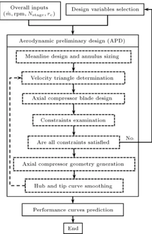
The axial compressor design, the process of which is illustrated in Figure 1 [1-3], is based on some overall characteristics including mass ow, pressure ratio, and minimum required eciency, which are determined in the gas turbine cycle analysis. In addition, designers try to obtain a compressor with maximum surge margin and minimum weight and dimension. Designing the compressor is composed of preliminary and detailed design steps. In the preliminary design, many features of the compressor such as stage number, rpm, blade
*. Corresponding author. Tel.: +98 21 77339794
E-mail addresses: [email protected] (R. Azizi); [email protected] (R. Ebrahimi); [email protected] (M. Ziabasharhagh)
loading, annulus size, and number of blades are deter-mined and the initial three-dimensional geometry of the blades is also constructed. The preliminary design is broken down into three steps of \aerodynamic design", \performance curve prediction", and \mechanical anal-ysis". The compressor preliminary design is done based on a set of design variables values. The aero-dynamical and geometrical features of the axial compressor are generated in the aerodynamic design step. Some or all of the design variables might be modied, provided that the compressor performance curves, which are derived in the performance prediction step, do not satisfy the predetermined overall design performance (i.e., mass ow, pressure ratio, surge margin, or e-ciency). Modication might also be essential in case of excessive stress or unsuitable blades frequencies, which are obtained in the mechanical analysis step.
Figure 1. Axial compressor design steps.
In the detailed design step, the preliminary com-pressor is used as the input and some of its spec-ications are modied through Computational Fluid Dynamic (CFD) and optimization tools [4,5]. In the de-tailed design, many of the preliminary design features are considered xed and this leads to high dependency of the nal design on the preliminary one. In fact, it should not be expected that a compressor with good performance characteristics would be obtained in the detailed design step if its aerodynamic preliminary design is far away from these characteristics. For this reason, the rst step in the development of a complete axial compressor design software is the development of an accurate aerodynamic preliminary design algo-rithm. The axial compressor aerodynamic preliminary design is done by the conventional design methods (i.e. meanline and streamline curvature methods) and conventional blade proles (i.e. NACA63-A4K6, NACA 65, DCA, and MCA). Dierent industrial axial com-pressors have applied these methods and proles in their preliminary or nal design. The axial compressors of M7A-03 8MW gas turbine [6], LM25001 General Electric gas turbine [7], and KHI 20MW gas turbine [8] are some examples.
As can be seen in Figure 1, the Aerodynamic Preliminary Design (APD) should be combined with a performance simulator, the combination of which is named Aerodynamic Preliminary Design and Sim-ulation (APDS) algorithm, as shown in Figure 2. The algorithm starts by the selection of some inputs which are categorized into two groups of overall inputs, comprised of the compressor mass ow, rpm, stage
Figure 2. Aerodynamic Preliminary Design and Simulation (APDS) algorithm.
number and mean radius, and aerodynamic design variables. Dierent designers might select various types of aerodynamic design variables. In some cases, the parameters such as the stagger angle or ow angles are considered as the aerodynamic design variables which are not independent of other variables. The presented algorithm employs the minimum number of independent basic variables, based on which other variables are computed. These variables are classied as the Velocity Triangle Determination (VTD) and Blade Design (BD) ones.
The Aerodynamic Preliminary Design (APD) block utilizes the following modules (Figure 2) [9,10]:
Meanline design and annulus sizing;
Velocity triangle determination;
Blade design;
Axial compressor three-dimensional geometry gen-eration;
Hub and tip curve smoothing.
The meanline design and annulus sizing module derive the average pressures in the inlet and outlet stations of the blade rows and, through them, the values of the hub and tip radii of the stations are computed. The velocity triangles are derived on the compressor
streamlines from the VTD design variables as inputs and the radial equilibrium and vortex equations. The blade design is the next step of algorithm, which uses the blade design variables, obtained velocity triangles, and incidence and deviation angles correlations. Then, a large number of designed constraints are examined and the design variables, in case of having one or more unsatised constraints, for one or more stages are modied. These constraints are necessary to satisfy the correlations ranges, to create the suitable blades loading and operating range and also to con-sider the overall geometry dimensions criteria. If all the constraints are satised, the three-dimensional geometry and meridional view of axial compressor will be generated. By use of the generated meridional view of the axial compressor, the hub and tip radii are modied in order to obtain the smooth curves for them. Through the modied radii, the velocity triangle determination, blade design, and geometry generation are iterated until the nal design is ex-tracted.
The other block of APDS algorithm is the pre-diction of performance curves in the design and o-design conditions, which may be done by the meanline, streamline, or CFD simulator. The meanline and streamline methods (conventional methods) have good accuracy if suitable loss and angles correlations are used. Nowadays, the CFD and conventional simulators are simultaneously employed in the axial compressor design [8]. The preliminary design optimization, which is done by the CFD simulator, is extremely time consuming (from one day to one week, depending on the used computational hardware); therefore, the development and modication of the meanline or streamline methods, due to their low computation time, are still ongoing [11,12]. However, it seems that using CFD codes in the future will be common and it may be substituted by meanline or streamlines methods
in the optimization problems with the computational hardware advances.
Although the performance curve prediction has major importance in the compressor design, it must be noted that the development of dierent simulators, with any level of accuracy, does not have any advantage unless they are combined with the APD tool. This is for the generation of the required geometrical inputs of the abovementioned simulators by the APD block. There are many publications available on the developed meanline and streamline simulators [13,14] or the CFD application in the compressor simulation [15,16], but small attention has been paid to the development of the compressor design modules. However, two research works [17,18] have evaluated the eects of some parameters such as solidity, blade angles, or chord on the performance of a single-stage compressor and have optimized these parameters through the meanline method.
In this research, the Aerodynamic Preliminary Design (APD) algorithm has been developed. In the next sections, the required design variables and necessary constraints are explained and the algorithm and computation method of any APD module are described. Finally, the algorithm is employed to redesign the NACA 8-stage transonic compressor [19] by using its design variables. The velocity triangles and blade specications of the redesigned compressor are compared with those of the NACA 8-stage compres-sors and the three-dimensional geometry of redesigned compressor is presented.
2. Design variables
The aerodynamic preliminary design is done by se-lecting some design variables. The essential design variables and their number for designing a single-stage compressor are tabulated in Table 1. As seen, a
Table 1. The aerodynamic preliminary design variables.
Type Variable Description Number
VTD
n; m Vortex exponent 1
1c; 2c Meanline ow coecients 1,1
Rc Meanline stage reaction 1
c Stage work coecient 1
Blade design
c Meanline solidity 2
tmax
c hub;tmaxc tip Blades hub and tip max. thickness ratio 2; 2
Fth Tip to hub chord ratio 1,1
AR Aspect ratio 2
rle; rte
(DCA proles) Leading and trailing edges radii 4
Total 15(NACA 65),19(DCA)
: The subscripts 1 and 2 represent the inlet and outlet stations of rotor; and subscript c indicates meanline position; : The comma separates the rotors and stator.
vast number of design variables must be selected by the designer. For example, the designer must select minimum 150 (all blades are designed with NACA 65 prole) and maximum 190 (all blades are designed with DCA proles) design variables for designing a 10-stage axial compressor.
Table 1 shows the maximum aerodynamic design variables which can be used in the aerodynamic prelim-inary design of axial compressors; however, all of them are not employed in the industrial designs due to the following reasons:
Dierent vortex types for dierent stages are not used in the preliminary design and one or two vortex types are usually applied for all stages;
In some industrial designs, the chord ratios of all the blade rows are considered equal to one and in other designs, the chord variation is applied for the front stages;
The lower values of leading and trailing edge radii lead to lower prole and shock losses. However, this reduction cannot be lower than the critical value since it leads to blade mechanical damage and deformation. Therefore, the leading and trailing edge radii of blades cannot be determined in the aerodynamic design and they depend on the mate-rials which are used in the blade manufacturing. According to the above reasons, the design variables number is decreased considerably. For example, the design variables for the aforementioned 10-stage axial compressor with four transonic and variable chord stages and single vortex-type are reduced to 88.
3. Design constraints
The design constraints are divided into aero-dynamical and geometrical ones, which are presented in Table 2. The absolute and relative ow angles and the ow deection angles are considered to observe the blade design correlations ranges. Diusion factor is a major parameter in the preliminary design to control the blades loading and losses and has major inuences on compressor eciency, surge margin, and weight. Its
Table 2. Preliminary design constraints.
Type Constraints
Aerodynamic
0 60 0 60 0 " 60 Diusion factor Max. inlet Mach number Geometrical Compressor length
Max. diameter
higher value causes low blade number, weight, and surge margin and its lower value leads to high blade number and weight and also low eciency. Due to the compressibility eects, the maximum inlet Mach num-ber is dependent on the performance characteristics of the blade proles. The geometrical constraints are dictated by the gas turbine system designer and they might be one of the compressor maximum diameters and length limits or both of them.
4. Meanline design and annulus sizing
The axial velocities in the mean radii of the inlet and outlet blade rows are obtained from the ow coecient denitions:
Ca;1= c1:U1; (1)
Ca;2= c2:U2; (2)
and the tangential velocities in these radii are com-puted through the simplied vortex equations [10]:
C1= Uc1
1 Rc 2c
; (3)
C2=
r1
r2
(C1+ cU1) ; (4)
c= HU2c
1 ; (5)
where Ca is the axial velocity, C is the tangential
velocity, cis the mean ow coecient, c is the mean
work coecient, Rcis the mean reaction, U is the blade
velocity, r is the radius, Hcis total enthalpy increase,
and subscripts 1 and 2 indicate the rotors inlet and outlet stations.
The Mach numbers in the inlet and outlet of the blades are computed by the total temperatures, which are derived from the work coecient denition and the obtained velocity triangles [10]:
Tt2= Tt1+ cU 2 c1
cp ; (6)
T = Tt C 2
2cp; (7)
M = pC
RT; (8)
M0= pW
RT; (9)
where Tt is the absolute total temperature, T is the
static temperature, C is the absolute velocity, W is the relative velocity, M is the Mach number, and M0is the
The blades are designed on the meanline radius by using the blade design variables and obtained velocity triangles. Using the Kock and Smith [20] and Aungier [10] loss models, the prole, secondary and end wall losses are obtained and pressures in the inlet and outlet of blades are calculated. Through the computed pressures and mass ow continuity, the necessary annulus area (hub and tip radii) for the design mass ow are computed. These radii are the initial values and are modied by computing the boundary layer displacement thickness. Experiments show that this thickness grows in the ow direction in the compressor, but its value tends to a constant value after several stages [10,19]. The computation of the displacement thickness eect is done by the famous meanline Kock [21] method for the rst ve stages and the other stage thicknesses are considered equal to the one in the 5th stage.
5. Velocity triangle determination
The velocity triangles are determined through Eqs. (10) to (13) [10]:
Ca@C@ra +Cr@(rC@r) =@H@r T@r@s; (10)
C1
UC1 =
(1 Rc)
RDn
c
2RDm; (11)
C2= C1UU1 2 +
U2 c1
U2; (12)
RD= rr
c; (13)
where H is the total enthalpy, s is the entropy, RD
is the non-dimensional streamline radius, n and m are the vortex exponents, and the subscript c indicates the meanline section.
Since in a good design, the entropy spanwise variation is small, the reduction in entropy gradient on the right-hand side of the radial equilibrium equation (Eq. (10)) has not made signicant errors in the veloc-ity triangles determination [6]. Using this assumption and solving the dierential equation of Eq. (10) in the radial direction, the meridional velocity can be obtained as:
C2
a(r) = (cUc)2+ 2
Z r rc @H @r C r
@(rC)
@r
dr: (14) The 5 VTD steps in the inlet and outlet stations of axial compressor rotors are described below:
1. The velocity triangles are determined on stream-lines. The initial streamline radii are computed through the constant area of the streamtubes
as-sumption and the hub and tip radii, which were determined in the meanline design and annulus sizing step;
2. The absolute tangential and axial velocities are computed on the streamlines by use of the vortex and radial equilibrium equations (Eqs. (10)-(13)). The other variables such as relative tangential velocity and absolute and relative ow angles are obtained through the triangles geometrical rela-tions [3,10];
3. The rotor outlet total temperature is obtained from the work coecient, inlet total temperature, and blade mean velocity (Eqs. (6)-(9)). The inlet total temperature in the rst rotor is equal to the ambient one and for the other rotors, it is equal to the outlet total temperature of the previous stage.
The static temperature and Mach number in the inlet and outlet stations and on the streamlines are derived from gas dynamic relations [3,10];
4. The variation of the static pressure on the stream-lines radii is nearly constant and vary linearly, especially in the design point. This has been shown in dierent published articles and open access reports [22]. By the radial uniformity of static pressure assumption and integral form of mass ow continuity, the mass ow which passes through the inlet and outlet stations is computed as:
_m = 2 Z rt
r Cardr: (15)
The static pressures in dierent stations are con-sidered equal to the one derived from the meanline design in the previous preliminary design step. The new streamlines radii are determined based on the equal mass ow of the streamtubes and total mass ow equal to the computed mass ow (Eq. (15));
5. Steps 2 to 4 are iterated so that the computed mass ow and velocity triangles converge to their nal value within the specied error.
6. Blade design
The blade design outputs include the following param-eters in all blade rows' streamlines:
Prole family;
Camber line type;
Maximum thickness/chord ratio;
Solidity;
Blade number;
Camber angle;
Stagger angle;
These parameters must be selected in consistence with the ow angles determined in the VTD step. The relations between the aforementioned parameters and ow angles are constructed with the incidence and deviation angle correlations. Dierent correlations for dierent blade proles have been represented during years [23-25]. Some of the incomplete correlations for the conventional proles are published in the open sources and many of them, especially for the new or transonic blade prole, are condential due to the considerable experiment expenses which are required for their derivation.
Vast numbers of blade and ow parameters are involved in these correlations, which make it impossible to compute all the blade parameters directly. There-fore, the blade should be designed through the selection of some blade parameters and the computation of the others in a trial and error method. The parameters which are selected in the blade design process include the solidity and maximum thickness/chord ratio on the streamlines and the blade aspect ratio.
The variation of blade thicknesses is computed through selecting a distribution type and the required thickness ratio values in some radii. The hyperbolic distribution is one of the most used distributions, which leads to low blade mass ow and centrifugal stress [19]. By use of this distribution and the thickness ratio in hub and tip sections, the thickness variation in dierent radii can be derived as:
tmax
c (r) = tmax
c
tip
+ tmaxc
tip
tmax
c
hub
!2
rtip r
rtip rhub
2
; (16) where tmax
c is the maximum thickness/chord ratio and
the subscripts \hub" and \tip" indicate the blade hub and tip sections.
Dierent solidity variation relations can be de-rived if dierent chord distributions are considered. The radial distribution of the solidity is calculated by Eq. (17), which is the result of the linear chord variation assumption [10]:
= c1 + (r1 + (r rhub)(Fth 1)=(rtip rhub) c rhub)(Fth 1)=(rtip rhub)
rc
r; (17) where is solidity and Fth is tip to hub chord ratio.
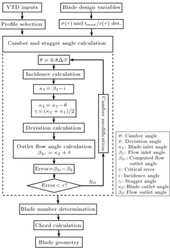
The blade design algorithm is shown in Figure 3. In addition to the blade design variables, the rotor inlet and outlet ow angles and tip inlet Mach number (the relative Mach number for rotors and the absolute Mach number for stators) are the required inputs of the blade design.
The prole is selected by the Mach number value.
Figure 3. Blade design algorithm.
Cumpsty [26] has mentioned that the NACA 65 proles can be used for the Mach number up to 0.80 and in the upper values, the DCA blades should be used. The MCA proles allow designers to have supersonic Mach number up to 1.3. Use of any proles in the developed algorithm is possible, but the designer must use their special incidence and deviation correlations.
After blade prole selection, the radial distribu-tion of solidity and maximum thickness/chord ratio are determined. The blade camber and stagger angles are calculated using the incidence and deviation angle correlations. This process is identical for all the blade sections in dierent radii and it is started by the camber angle assumption equal to 80 percent of the ow deection. The incidence angle is computed and the blade inlet angle is obtained from it and ow inlet angle. The blade outlet and stagger angle are derived by the geometrical relations and the deviation angle is calculated through them. The outlet ow angle is obtained from the computed blade outlet and deviation angles. This angle is compared with the outlet ow angle, which is determined in the VTD step. The camber angle is modied to converge to the computed and VTD outlet ow angles.
The blade number determination is the next step of the blade design and is done using the annulus radii,
mean solidity, and aspect ratio: Z = c2rc c
c ; (18)
cc= rtipARrhub; (19)
where Z is the blade number, ccis the mean chord, and
AR is the aspect ratio.
If the calculated blade number is a decimal digit, the nearest integer number will be chosen as the num-ber of blades. Finally, the chord magnitudes in dierent radii can be calculated by the solidity distribution and blade number:
c = 2rZ : (20)
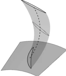
7. Axial compressor geometry generation The output of the preliminary design is the three-dimensional geometry of the blades which will be used in the other compressor design steps such as the mechanical analysis and the detailed design (Figure 1). The geometrical outputs of the meanline design and annulus sizing, VTD, and blade design modules are the streamlines radii and blade specications (i.e. the cam-ber and stagger angles, the maximum thickness/chord ratio, and the leading and trailing edges radii) on the streamlines. These data cannot be used in other design steps and they should be changed to the points and nodes coordinates of the blades and annulus geometry. For this reason, a code has been developed which generates the three-dimensional blades geometry and assembles them over the compressor axis. This code produces the blade section proles coordinates on the streamline and stacks them through a guideline curve which connects the area centroids of the blade sections (Figure 4). Figures 5 and 6 show the generated
Figure 4. Blade sections and guideline curve.
Figure 5. BBC-Sulzer compressor geometry.
Figure 6. NACA 5-stage compressor geometry.
geometry of BBC/Sulzer compressor [22] and NACA 5-stage compressor [27] from the developed code.
These gures are plotted in the Tecplot software. However, the developed code can generate the input les proper for the numerical software such as ANSYS CFX and modeling software such as UNG NX. These les considerably reduce the modeling time of the axial compressor in the software. In addition, some mechan-ical specications such as the blades mass and sections centrifugal stress can accurately be computed. The volumes are compared in Tables 3-5; also, centrifugal forces of BBC-Sulzer blades, which have been derived from the developed code, have been compared with those from UNG NX and ANYSY software.
8. Algorithm evaluation
The APD algorithm is applied to a computer code which has been developed with FORTRAN program-ming language. In this section, the results of the developed code for the NACA 8-stage transonic axial
Table 3. Rotors' volume of BBC-Sulzer compressor (mm3).
Stage Code SIMENSE NX Dierence (%)
1 67857.88 67725.25 0.20
2 22925.23 22896.16 0.13
3 14872.78 14822.54 0.34
Table 4. Stationary blades' volume of BBC-Sulzer compressor (mm3).
Blade
type Code Ansys
Dierence (%) IGV 63869.01 64142.45 -0.43 OGV 7461.83 7460.12 0.02
Stators
1 33170 33179.61 -0.03 2 15296.13 15288.04 0.05 3 9863.59 9857.41 0.06 4 6441.17 6443.20 -0.05 Table 5. Rotors' root centrifugal force of BBC-Sulzer compressor (N).
Stage Code Ansys Dierence (%) 1 248969.80 248810 0.06
2 95113.61 95095 0.02
3 66216.72 66173 0.07
4 46868 46834 0.07
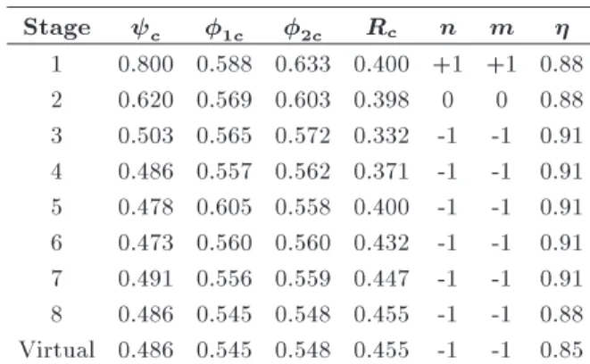
Table 6. VTD design parameters.
Stage c 1c 2c Rc n m
1 0.800 0.588 0.633 0.400 +1 +1 0.88 2 0.620 0.569 0.603 0.398 0 0 0.88 3 0.503 0.565 0.572 0.332 -1 -1 0.91 4 0.486 0.557 0.562 0.371 -1 -1 0.91 5 0.478 0.605 0.558 0.400 -1 -1 0.91 6 0.473 0.560 0.560 0.432 -1 -1 0.91 7 0.491 0.556 0.559 0.447 -1 -1 0.91 8 0.486 0.545 0.548 0.455 -1 -1 0.88 Virtual 0.486 0.545 0.548 0.455 -1 -1 0.85
compressor [19], which is called NACA compressor in the rest of the article, as well as the rpm of 13380 and mass ow of 29.5 (kg/s) are evaluated. The design variables of NACA compressor were used as the inputs of the developed code. The VTD and BD design variables of NACA compressor are tabulated in Tables 6 and 7, respectively.
In addition, the following rules have been used in the NACA compressor design:
1. Because of reasons unknown to the authors of the present paper, the velocity triangles in the outlets of rotors 3 to 8 are the average of those ob-tained through the radial equilibrium equation and the throughow method. In the straight-throughow method, the axial velocity in the outlet rotor on any streamline is the average of the stage inlet and outlet:
Ci
a2 = 0:5 Ca2;REEi + Ca2;STFi
; (21)
Ci a2;STF=
Ci
a1;REE+ Cz1;REEi+1
=2; (22) where i is stage number, REE indicates radial equilibrium equation, and STF indicates straight-through ow method;
2. The rst and second rotors have been designed by the DCA proles. The constant incidence angle of 4.0 (deg) (Eq. (23)) and deviation angle correlation of Eq. (24) have been used to design these blades:
i = 4; (23)
= 0:475
: (24)
The other blades have been designed by the NACA 65 proles through Herrig et al. [23] angle correlations.
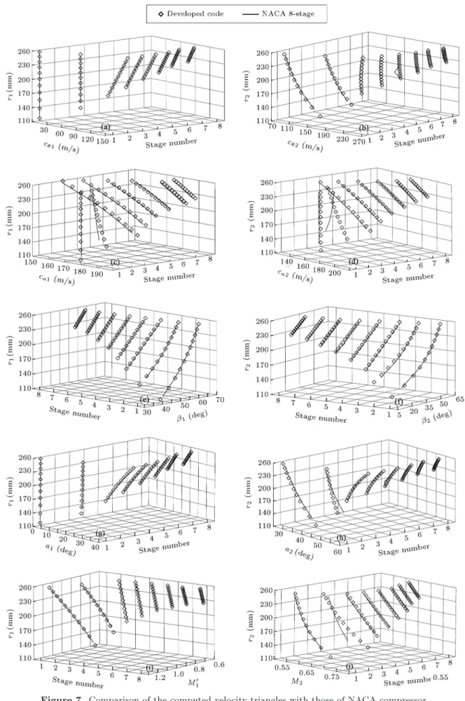
By employing the abovementioned rules in the VTD and blade design modules and using the de-sign variables of Tables 6 and 7, the NACA 8-stage compressor has been redesigned through the developed APD code. The comparison of the computed velocity triangles of the redesigned compressor with those of NACA compressors is shown in Figure 7.
Except for the velocity triangles values of rotor No. 2, which are dierent from those obtained by the developed code, the other rotors' velocity triangles have a good conformity with the NACA compressor. The dierences in velocity triangles of rotor No. 2
Table 7. Blades design parameters.
Stage AR c Fth tmaxc hub tmaxc tip
Rotor Stator Rotor Stator Rotor Stator Rotor Stator Rotor Stator
1 1.47 2.23 1.345 1.036 1.25 1 0.095 0.06 0.05 0.06
2 1.15 1.77 1.392 1.2 1.25 1 0.086 0.06 0.048 0.06
3 2.19 1.99 1.134 0.897 1 1 0.10 0.06 0.06 0.06
4 1.85 1.68 1.275 0.898 1 1 0.10 0.06 0.06 0.06
5 1.56 1.39 1.294 0.948 1 1 0.08 0.06 0.06 0.06
6 1.31 1.17 1.232 0.979 1 1 0.08 0.06 0.06 0.06
7 1.09 0.98 1.205 1 1 1 0.08 0.06 0.06 0.06
are due to the dierence in the values and trends of the axial velocities in the redesigned and NACA compressors, the reason of which is unknown to the writers. The surprising point is that the tangential velocities in the inlet and outlet of this rotor are equal in the redesigned and NACA compressors. Based on the radial equilibrium equation, the axial velocity reported for the NACA compressor should be the same as that obtained through the code. Since the axial velocity value and distribution in the other blades rows of NACA compressor are the same as the ones resulted from the code, the VTD module is valid and the probable code errors are not the reason behind the dierences of rotor No. 2. In addition, the analytical computation for this rotor shows similar values and trends to the code results. For this reason, the writers guess the reported values for rotor No. 2 may have been wrong or other additional assumptions may have been applied for this rotor, which have not been mentioned in [19].
The NACA compressor velocity triangles have been derived on the axial sections, whereas in the developed code, the streamlines radius variations are incorporated in the VTD. This dierence in the com-putation methods leads to some small dierences of velocity triangles between the redesigned and NACA compressors (except for rotor No. 2) (Figure 7).
Figure 8 compares the derived blades camber and stagger angles from the APD code with the ones of NACA compressor. As seen, good conformity in values and trends exists between the rotors blade specications of NACA compressor and the computed
ones (Figure 8(a) and (c)). The computed stators stagger angles have good conformity with the NACA compressor; however, this conformity is not seen in all the stators camber angles. The dierence in these values results from the dierence between the ow angles and solidity distributions of the code and NACA compressor. In addition, the NACA compressor stators No. 5-8 have been designed with constant values, while this assumption has not been used in the APD code.
The meridional view of NACA compressor is compared with that of the redesigned compressor in Figure 9. Dierences are seen in the hub and tip radii of these compressors. These dierences are due to the dierent annulus sizing methods which have been applied for the NACA compressor and the developed code. The annulus sizing for the NACA compressor is done by the assumption of total pressure uniformity in the radial direction. The total pressure was computed through the selection of stages and rotors isentropic
Figure 9. Meridional view comparison of the redesigned and NACA compressors.
eciency as input. The applied method is completely dierent from the used method in this article. It must be noted that the assumption of the total pressure uniformity is in contrast with the ow physics [22]; however, the static pressure uniformity used in the developed code satises the ow patterns [22]. In addition, the determination of the stage eciency as input requires to be highly experienced in the axial compressor designing; however, the used mean-line design in developed code can derive the static pressure in any station through the empirical loss correlations.
The blades axial coordinates are also dierent in NACA and redesigned compressors. It is because of dierent chord values of the compressors' blades. As mentioned, the chord magnitude is dependent on the aspect ratio and blade height (Eq. (19)). Since the blades aspect ratio of the redesigned compressor is equal to that of the NACA compressor, the chord dierence is the result of the dierence between the compressors hub and tip radii, which leads to lower overall length, of about 30 mm, of NACA compressor than that of the redesigned one.
The three-dimensional geometry of the redesigned compressor is shown in Figure 10. This geometry is the nal outcome of the aerodynamic preliminary design algorithm, which is generated through the three-dimensional geometry generation module and plot by the Tecplot. However, the required input les for the Computational Fluid Dynamics (CFD) software such as CFX and the mechanical and modeling software such as UNG NX can be generated. The blades sections are generated by the 58 points on their suction and pressure surfaces and 7 points for the leading or trailing edges. These numbers of points result good quality surfaces. The quality of the geometry surfaces and points numbers are shown in Figure 11 for the rst rotor.
The computation of the weight and centrifugal stresses is the other ability of the developed geometrical modules. Tables 8 and 9 represent these parameters for the redesigned compressor and compare them with the NACA ones. As seen, the blade weights of
Figure 10. Three-dimensional geometry of the redesigned compressor.
Figure 11. Three-dimensional geometry of the rst rotor. Table 8. Blades weight comparison of redesigned and NACA compressors.
Stage Rotors Stators
NACA Redesigned NACA Redesigned
1 6.56 7.71 2.03 2.59
2 4.60 5.23 2.12 2.40
3 1.86 2.03 1.02 1.19
4 1.73 1.84 0.84 0.92
5 1.24 1.33 0.71 0.78
6 0.93 1.01 0.58 0.63
7 0.73 0.77 0.48 0.54
8 0.59 0.65 0.41 0.42
Total 18.24 20.57 8.19 9.47
Table 9. Rotors root centrifugal stress comparison of redesigned and NACA compressors (MPa).
Stage NACA Redesigned 1 325.92 326.82 2 263.91 260.77 3 204.99 202.48 4 173.68 168.91 5 159.28 159.13 6 131.00 132.28 7 108.31 108.18
8 90.98 92.65
the redesigned compressor are heavier than those of the NACA compressor and the redesigned compressor weight is 12(%) larger than the NACA compressor weight. This shows the annulus sizing importance in the compressor weight in addition to its eect on the aerodynamic and performance curves. The rotors centrifugal stresses in the root section of the aforementioned compressors are compared in Table 8. This table shows the same centrifugal stress in two compressors, which is due to increasing root section areas of the redesigned compressor.
9. Conclusion
The Aerodynamic Preliminary Design (APD) is a major step in the axial compressor design because of the high dependency of the nal design on its results. In this article, a preliminary design algorithm has been developed. The dierent steps of the preliminary design, the required design variables, and the design constraints have been introduced. The algorithm is applied to a computer code through FORTRAN pro-gramming language and its results have been evaluated through the NACA 8-stage compressor. By developing a geometry generation code, the compressor blade geometries and its meridional view, which can be used in other designing and analysis steps, can be derived.
References
1. Larosilierw, L.M., Wood, J.R., Hathaway, M.D., Medd, A.J. and Dang, T.Q. \Aerodynamic design study of advanced multistage axial compressor", Re-port ARL-TR-2859, NASA (2002).
2. Turner, M.G., Merchant, A. and Bruna, D. \Applica-tions of a turbomachinery design tool for compressors and turbines", 43rd AIAA/ASME/SAE/ASEE Joint Propul. Conf. and Exhib., Cincinnati, OH, USA (2007).
3. Saravanamuttoo, H.I.H., Rogers, G.F.C., Cohen, H. and Straznicky, P., Gas Turbine Theory, 6th Edn., Pearson Education, Canada (2008).
4. Okui, H., Verstraete, T., Braembussche, R.A. and Al-salihi, Z. \Three-dimensional design and optimization of a transonic rotor in axial ow compressors", J. of Turbomach., 135(3) (2013).
5. Oyama, A., Liou, M. and Obayash, S. \Tran-sonic axial ow blade optimization: evolutionary algorithm/three-dimensional Navier-Stocks solver", J. of Propul. and Power, 20(4), pp. 612-619 (2004).
6. Tanimura, K., Murakami, N., Matsuoka, A., Ishida, K., Kato, H., Sakai, T., Taniguchi, T. and Taki, H. \Development of an 8MW-class high-eciency gas turbine, M7A-03", Proc. of ASME Turbo Expo: Power for Land, Sea and Air, Montreal, Canada (2007).
7. Wadia, A.R., Wolf, D.P. and Haaser, F.G. \Aerody-namic design and testing of an axial ow compressor with pressure ratio of 23.3:1 for the LM25001 gas tur-bine", J. of Turbomach., 124(3), pp. 331-340 (2002).
8. Ikeguchi, T., Matsuoka, A., Sakai, Y. and Sakano, Y. \Design and development of a 14-stage axial compres-sor for industrial gas turbine", Proc. of ASME Turbo Expo: Turbine Tech. Conf. and Exp., Copenhagen, Denmark, pp. 125-134 (2012).
9. Smith, H.L. \Axial compressor aero design evolution at general electric", J. of Turbomach., 124(3), pp. 321-330 (2002).
10. Aungier, R.H., Axial Flow Compressors: A Strategy for Aerodynamic Design and Analysis, ASME Press, New York, USA (2003).
11. Boyer, K.M. and O'Brien, W.F. \An improved stream-line curvature approach for o-design analysis of tran-sonic axial compression systems", J. of Turbomach., 125(3), pp. 475-481 (2003).
12. Templalexis, I., Pilidis, P., Pachidis, V. and Kotsiopou-los, P. \Development of a two dimensional streamline curvature code", J. of Turbomach., 133(1) (2010).
13. Shadaram, A., Fathi, A. and Azizi, R. \Optimization of variable stator's angle for o design compression system using streamline curvature method", ASME Turbo Expo.: Power for Land, Sea, and Air, 7, Orlando, USA, pp. 525-532 (2009).
14. Madadi, A. and Benisi, A.H. \Performance predicting modeling of axial ow compressor at design and o-design conditions", ASME Turbo. Expo.: Power for Land, Sea, and Air, 6, Berlin, Germany, pp. 317-324 (2008).
15. Fritsch, G., Hoeger, M., Blaha, C. and Bauer, D. \Viscous three-dimensional simulation of transonic compressor stage on parallel hardware", J. of Propul. and Power, 16(3), pp. 388-396 (2000).
16. Brandvik, T. and Pullan, G. \An accelerated 3D Navier-Stokes solver for ows in turbomachines", J. of Turbomach., 133(2) (2010).
17. Chen, L., Sun, F. and Wu, C. \Optimum design of a subsonic axial-ow compressor stage", Appl. Energy, 80(2), pp. 187-195 (2005).
18. Chena, L., Luoa, J., Suna, F. and Wub, C. \Design eciency optimization of one-dimensional multi-stage axial-ow compressor", Appl. Energy, 85(7), pp. 625-633 (2008).
19. Voit, H.C. \Investigation of a high pressure ratio eight stage axial ow research compressor with two transonic inlet stage I- aerodynamic design", Report NACA-RM-E53124, Lewis Flight Propul. Lab., Cleveland, Ohio, USA (1953).
20. Koch, C.C. and Smith, L.H. \Loss sources and mag-nitudes in axial-ow compressors", J. of Eng. Gas Turbines and Power, 98(3), pp. 411-424 (1976).
21. Koch, C.C. \Stalling pressure rise capability of axial ow compressor stages", J. of Eng. Gas Turbines and Power, 103(4), pp. 645-656 (1981).
22. Hirsh, C. and Denton, J.D. \Through ow calcula-tions in axial turbomachines", Report AGARD-AR-175 (1981).
23. Herrig, L.J., Emery, J.C. and Erwin, J.R. \System-atic two-dimensional cascade tests of NACA 65-series compressor blades at low-speeds", Report NACA-TN-9916, Langley Aero. Lab. (1951).
24. Konig, W.M., Hennecke, D.K. and Fottner, L. \Im-proved blade prole loss and deviation angle models for advanced transonic compressor blading: Part I-a model for subsonic ow", J. of Turbomach., 118(1), pp. 73-80 (1996).
25. Banjac, M., Petrovic, M.V. and Wiedermann, A. \A new loss and deviation model for axial compressor inlet guide vanes", J. of Turbomach., 136(7) (2014).
26. Cumpsty, N.A., Compressor Aerodynamics, Longman Scientic and Technical, UK, pp. 46-129 (1989).
27. Sandercock, M.D., Kovach, K. and Lieblein, S. \Ex-perimental investigation of a 5-stage axial ow research compressor with transonic rotors in all stages I- com-pressor design", Report NACA-RM-E54F24, Lewis Flight Propul. Lab., Cleveland, Ohio, USA (1954).
Biographies
Rohollah Azizi is a PhD candidate in Aerospace Engineering at K. N. Toosi University. He received his BSc degree from Shahrekord University in Mechanical Engineering and his MSc degree from K. N. Toosi University in Energy Conversion. He has been doing research for more than 7 years on axial compressor simulation and design and has managed to develop several aero-dynamical and thermos-dynamical codes. He has cooperated with some Iranian turbomachinery companies such as TUGA, Turbotec, Monenco, and Tadbirgaran.
Reza Ebrahimi is an Associate Professor and now is the head of Aerospace Engineering Faculty of KN-TOOSI University. He received his PhD and MSc degrees from Sharif University in Thermal Science. His major interests are reactive ow, propulsion (gas turbines and rockets), CI and SI engines simulation, heat and mass transfer, raried gas dynamic, and energy conversion systems. He has published several articles in dierent journals and has cooperated in dierent industrial projects.
Masoud Ziabasharhagh is an Associate Professor at K.N. Toosi University. He was the Head of Me-chanical Engineering Faculty for several years. He has received his PhD degree from Craneld University and his MSc degree from Birmingham University in Energy Conversion. His major interests are power plant, thermodynamic, and turbomachinery. He has published several articles in various journals and won the second place in Khwarizmi Festival for constructing steam power plant deaerator.