43
Chapter 2
Pump Types and Performance Data
J. F. Gülich, Centrifugal Pumps,
DOI 10.1007/978-3-642-40114-5_2, © Springer-Verlag Berlin Heidelberg 2014
Abstract Centrifugal pumps are used for transporting liquids by raising a specified volume flow to a specified pressure level. Pump performance at a given rotor speed is described by the rate of flow delivered, the pressure rise achieved, the power absorbed at the coupling, the efficiency and the NPSH. Depending on the appli-cation a broad variety of pump types are offered on the market. All of these have at least one impeller and a collector where most of the kinetic energy at the impel-ler outlet is converted into static pressure. Different forms of impelimpel-lers, diffusers, volutes and inlet casings are available to build radial, semi-axial or axial, single- or multistage, pumps mounted in horizontal or vertical position – as most suitable for the specific application.
2.1 Basic Principles and Components
Centrifugal pumps are turbomachines used for transporting liquids by raising a specified volume flow to a specified pressure level. The energy transfer in turboma-chines is invariably based on hydrodynamic processes for which characteristically all pressure and energy differences are proportional to the square of the circumfer-ential rotor speed. By contrast, positive displacement pumps (e.g. piston pumps)
essentially deliver the same volume Vstroke at each stroke independently of flow
velocity or rotor speed n. The flow rate then becomes Q = n × Vstroke; the pressure
rise results solely from the imposed back pressure.
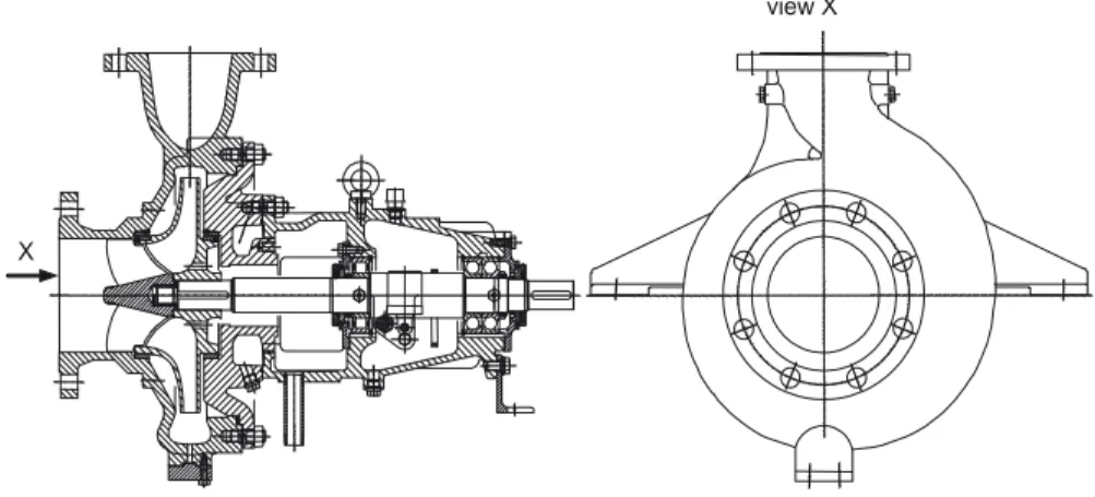
A centrifugal pump according to Fig. 2.1 is essentially composed of a casing, a
bearing housing, the pump shaft and an impeller. The liquid to be pumped flows through the suction nozzle to the impeller. The overhung impeller mounted on the shaft is driven via a coupling by a motor. The impeller transfers the energy neces-sary to transport the fluid and accelerates it in the circumferential direction. This causes the static pressure to increase in accordance with kinetics, because the fluid flow follows a curved path (Sect. 1.4.1). The fluid exiting the impeller is deceler-ated in the volute and the following diffuser in order to utilize the greatest possible
part of the kinetic energy at the impeller outlet for increasing the static pressure. The diffuser forms the discharge nozzle.
A shaft seal, e.g. a stuffing box or a mechanical seal, prevents the liquid from es-caping into the environment or the bearing housing (the shaft seal is not represented
in Fig. 2.1). As shown in Fig. 2.1, an inducer may be added at the impeller inlet for
improving the suction performance (Sect. 7.7). However, most applications do not use an inducer.
Impeller and casing are separated by a narrow annular seal through which some leakage flows back from the impeller outlet to the inlet. A second annular seal on the rear shroud serves the purpose of counterbalancing the axial forces acting on the impeller front and rear shrouds. The leakage through this seal flows back into the suction chamber through “axial thrust balance holes” which are drilled into the rear shroud.
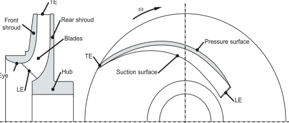
The impeller can be described by the hub, the rear shroud, the blades transfer-ring energy to the fluid and the front shroud. In some applications the front shroud is omitted. In this case the impeller is termed “semi-open”.
Figure 2.2 shows the meridional section and the plan view of an impeller. The
leading face of the blade of the rotating impeller experiences the highest pressure for a given radius. It is called pressure surface or pressure side. The opposite blade surface with the lower pressure accordingly is the suction surface or suction side. When looking into the impeller eye we see the suction surface. Therefore, it is sometimes called the “visible blade face” or the “lower blade face”, whilst the pres-sure surface, not visible from the impeller eye, is called the “upper blade face”.
These terms are ambiguous and should be avoided. Also defined in Fig. 2.2 are the
leading edge LE and the trailing edge TE of the blade. Figure 2.3 shows an impeller
designed by means of a 3D-CAD program (the front shroud is removed).
According to the performance and application requirements a wealth of differ-ent pump types is available which can be classified by differdiffer-ent aspects. Table 2.1 Gives an overview of the different types of impellers, diffusing elements, inlet
cas-YLHZ;
;
45 2.1 Basic Principles and Components
ings and combinations of these elements. The following points A to G relate to the corresponding frames in Table 2.1:
A. Depending on the direction of the flow at the impeller exit we distinguish radial, semi-axial and axial impellers. Accordingly the terms radial, semi-axial and axial pumps are used; the latter are also called “propeller pumps”.
B. Impellers with a front shroud are called “closed impellers”, those without a front shroud are termed “semi-open impellers” and those with large cut-outs in the rear shroud are designated as “open impellers”.
C. According to the flow direction at the diffuser inlet there are radial, semi-axial and axial diffusers. Vaneless diffusers are rarely built.
D. The most frequent type of diffusing element for a single-stage pump is a volute casing. Sometimes there is a concentric annulus or a combination of annulus and volute.
E. Most single-stage, single-entry pumps have an axial inlet nozzle as in Fig. 2.1.
Inline pumps and between-bearing impellers require radial inlet chambers
(Figs. 2.5–2.13). Vertical pumps are often fed via a suction bell (also called
“bell-mouth”) from a sump in a wet pit installation (see Fig. 2.15 and Sect. 11.7.3).
Fig. 2.3 Radial impeller
nq= 85, 3D-model, Sulzer Pumps
+XE 5HDUVKURXG
%ODGHV )URQW
VKURXG
7(
/(
6XFWLRQVXUIDFH
3UHVVXUHVXUIDFH
/( 7(
(\H
Z
Fig. 2.2 Meridional section and plan view of a radial impeller, LE: Leading edge, TE: Trailing
7DEOH+\GUDXOLFSXPSFRPSRQHQWVDQGDUUDQJHPHQWV &RPSRQHQWRU
IHDWXUH 5DGLDO 6HPLD[LDO $[LDO
$,PSHOOHUIRUP &KDUDFWHULVWLFIORZ GLUHFWLRQDWLPSHOOHU H[LW
%,PSHOOHUW\SH &ORVHGVKURXGHG
6HPLRSHQ
2SHQ
&'LIIXVHU
&KDUDFWHULVWLFIORZ GLUHFWLRQDWGLIIXVHU LQOHW
5DGLDO
6HPLD[LDO
'2XWOHWFDVLQJ
6LQJOH 'RXEOH
YROXWH YROXWH
&RQFHQWULFDQQXOXV
&RQFHQWULFDQQXOXV SOXVYROXWH
(,QOHWFDVLQJ $QQXODULQOHWFKDPEHU
6\PPHWULFLQOHW
$V\PPHWULFLQOHW
),PSHOOHUVLQ
VHULHVPXOWLVWDJH SXPSV
0XOWLVWDJHVHPLD[LDOSXPSVVHH)LJ
*,PSHOOHUVLQ SDUDOOHOGRXEOH HQWU\LPSHOOHUV
6LQJOHVWDJH
47 2.2 Performance Data
F. If the pressure generated by one impeller is insufficient, several impellers are arranged in series resulting in a “multistage” radial or semi-axial pump. In that type of pump the diffusers include return vanes, which direct the fluid to the impeller of the subsequent stage. Multistage pumps may be equipped with double volute casings instead of diffusers; in that case the fluid is directed to the subsequent stage through appropriately shaped channels.
G. Double-entry radial impellers are used when greater flow rates must be transpor-ted. Double-entry pumps may be built as single-stage or multistage.
The components and characteristics shown in Table 2.1 may be combined in many ways for the optimization of pumps for different requirements. Performance data, design specifications, fabrication methods, installation and operation conditions all have an impact on that optimization.
Because of their complicated, three-dimensionally curved surfaces, impellers, volute casings and diffusers are usually fabricated as castings. In some applications impellers and diffusers are manufactured by NC-milling. Small pumps are often made from plastics. There are even impellers and diffusers made entirely from sheet metal. Although simplified hydraulic shapes may be required to ease their manufac-turing, the efficiencies achieved with sheet metal pumps are quite good because of the smooth hydraulic surfaces and the small vane blockage.
2.2 Performance Data
The performance data of a centrifugal pump are described by:
• the flow rate Q which is normally defined as the useful volume flow through the discharge nozzle
• the specific work Y or the head H = Y/g
• the power consumption P at the pump coupling (“brake horsepower”) • the efficiency η at the pump coupling
• the net positive suction head NPSH at the pump inlet, or the net positive suction
energy NPSE = g × NPSH.
In addition to these data, the speed n of the pump rotor is indispensable.
2.2.1 Specific Work, Head
The specific work Y is the total useful energy transmitted by the pump to the fluid
per unit of mass. Y is measured between the suction and the discharge nozzle. Y is identical to the total useful (isentropic) enthalpy rise Δhtot. In incompressible flow
we have Y = Δhtot= Δptot/ρ (see Sect. 1.2.2). In practice the head H = Y/g is
common-ly used (also termed “total dynamic head”). It has to be comprehended as specific
Y htot p p g H
2 tot 1 tot
, _ ,
(2.1)
The total pressure according to Eq. (1.7) consists of the static (or system) pressure p, the pressure corresponding to the geodetic head ρ × g × z and the stagnation pressure ½ρ × c2. With reference to Table 2.2, the total dynamic head of a pump measured between the suction and the discharge nozzles results from the difference of the total
pressures expressed as heads H = Hd − Hs (subscript d = discharge nozzle; s = suction
nozzle).
(2.2)
In this equation all energies are expressed as “energy heads”: the static pressure heads p/(g × ρ) measurable at the suction or the discharge nozzle, the potential
energy z and velocity heads c2/(2g). Head and specific work are independent
of the density or the type of the medium. Thus a pump (in theory) produces the same head when transporting water, mercury or air. But by no means does
it create the same pressure rise ∆p = ρ × g × H that could be measured by a ma
-nometer. All pressure differences, powers, forces and stresses are proportional
to the density.
Table 2.2 shows how the different components that make up the head must be taken into account in a measurement or a calculation. The plane of reference should be chosen at the shaft centerline in the case of horizontal pumps. For pumps with a vertical or inclined shaft, the intersecting point of the shaft axis with a horizontal line drawn through the center of the inlet of the upper suction
impeller is used as plane of reference, [N.1]. Manometer readings at other levels
should be corrected to the plane of reference, [N.2]. As only pressure differences
are taken into account for calculating the head, values of absolute pressure or gage pressure (i.e. pressure above atmospheric) may be used in Eqs. (T2.2.1 to 2.2.6).
In order to ensure the specified volumetric flow rate through a given pumping
plant, the pump must deliver a certain head which is called the required head HA
of the plant. It is calculated from Bernoulli’s equation taking into account all head losses in the system (except losses in the pump), see Table 2.2, Eq. (T2.2.6). Dur-ing steady operation the head of the pump equals the required head of the plant:
H = HA.
2.2.2 Net Positive Suction Head, NPSH
When the pressure in a liquid drops below the vapor pressure, a portion of the fluid will evaporate. Excess velocities due to the flow around the blade leading
H p p
g z z
c c
2g
d s
d s d
2 s
2
49 2.2 Performance Data
7DEOH7RWDOG\QDPLFKHDGDQGQHWSRVLWLYHVXFWLRQKHDG13 6+ 3XPS (T 3ODQW (T +HDGDWLQOHW V Y H V V V V + + J F ] J S + − = + + ρ J F ] J S + H H H H + + ρ +HDGDWRXWOHW G Y D G G G G + + J F ] J S + + = + + ρ J F ] J S + D D D D + + ρ 7RWDOG\QDPL FKHDG +WRW + G +V + + G +V + D +H + YG + YV J F F ] ] J S S + V G V G V G WRW − + − + ρ − V Y G Y H D H D H D $ + + J F F ] ] J S S + + + − + − + ρ − 7RWDOG\QDPLFKHDGDERYHYDSRU SUHVVXUH SY ZLWKS DEV S DPE S V 136+ + V S DPE SY ρ î J 136+ $ + V SDPE SY ρ î J J F ] J S S 136+ V V DEV V Y + + ρ − V Y H H Y DEV H $ + J F ] J S S 136+ − + + ρ − 6WDWLFSUHVVXUHLQVXFWLRQQR]]OH
()
()
V H V Y 6 H DEV H DEVV F F + ] ] J S S − ρ + − − ρ + + 0D[LPXPDOORZDEOHJHRGHWLFVXFWLRQKHDG] H QHJDWLYH 0LQLPXPUHTXLUHGJHRGHWLFVXFWLRQKHDG] H SRVLWLYH D J F J S S + 136+ ] H Y DEVH VY 5 H + − ρ − − + ]D ] ] ] +D FD SD]G ]V
+G FG SG +V FV SV ]H +H FH SH D • 1RWHVLJQSRVLWLYHRUQHJDWLYHRIDOOOHYHOV] • +YV +YG KHDGORVVHVLQVXFWLRQDQGGLVFKDUJHSLSH V UHVSHFWLYHO\ • SV SG VWDWLFSUHVVXUHVPHDVXUHGDWVXFWLRQDQGGLVFKDUJHEUDQFKUHVS • SH SD VWDWLFSUHVVXUHVDERYHVXFWLRQDQGGLVFKDUJHOLTXLGOHYHO VUHVS UHIHUHQFHGDWXP
edge cause a local pressure drop, which may lead to such partial evaporation. This phenomenon is called “cavitation”; it is discussed in detail in Chap. 6. Extensive cavitation can impair the performance or even interrupt the flow. Therefore the ap-proach flow conditions at the suction nozzle are an important criterion for the layout and selection of a pump. The relevant parameter is the “net positive suction energy” NPSE or the “net positive suction head” NPSH. It is defined as the absolute suction
head Hs,abs minus the vapor pressure expressed as head pv/(ρ × g). Table 2.2 gives
the equations and definitions. We distinguish between the (usually measured) NPSH
of the pump which is necessary in order to fully or partially suppress cavitation
(“NPSH required” or NPSHR) and the NPSH available in the plant (NPSHA). Since
the vapor pressure pv is given in the water/steam tables as an absolute pressure,
ab-solute pressures must be inserted into Eqs. (T2.2.7 and 8) for calculating the NPSH. From Bernoulli’s equation we can calculate the absolute pressure at the highest point of the impeller situated at a distance “a” above the rotor axis. This pressure must never be allowed to fall below a level at which an unacceptably large volume of vapor would form at the impeller inlet due to cavitation. Any given pump has its
required NPSHR= f(Q) which corresponds to a specific amount of cavitation. The
NPSHA or the liquid level ze which is necessary for the plant to operate properly
must be calculated from the condition NPSHA> NPSHR, Eq. (T2.2.10), (Chap. 6).
• If ze calculated from Eq. (T2.2.10) results as negative, this value is the maximum admissible geodetic suction lift:zs,geo,max = −ze.
• If Eq. (T2.2.10) yields a positive value, the pump needs a geodetic suction head,
which means that the liquid level must be above the pump. As demonstrated by
Eq. (T2.2.10), this always applies to the pumping of saturated (boiling) liquids,
because in that case pe,abs= pv.
With the exception of some special pump types, centrifugal pumps must be filled with liquid for start-up; they are not “self-priming” and thus cannot evacuate the air from the suction pipe.
Types of self-priming pumps include side channel and liquid-ring pumps. Radial impellers are sometimes combined with one side-channel stage in order to allow self-priming of radial pumps, Sect. 2.3.4.
2.2.3 Power and Efficiency
Since the specific work represents the energy transferred per unit mass, the useful
power Pu of a pump is obtained by multiplying the transported mass flow m = ρ × Q by the specific work Y:
(2.3)
The power P needed at the coupling is greater than the useful power because it includes all losses of the pump. The ratio of both values is the pump’s efficiency η:
51 2.3 Pump Types and their Applications
(2.4)
2.2.4 Pump Characteristics
When the flow rate of a pump varies, the head, the power consumption and the efficiency change too. Plotting these quantities against the flow rate we obtain the
“pump characteristics”, Fig. 2.4. At a certain flow rate the pump efficiency has a
maximum value called the “best efficiency point” (BEP). The pump is designed for
this BEP which is characterized by Qopt, Hopt, Popt and ηopt at a given speed.
The operation point of a pump is invariably where the head generated by the
pump equals the head required by the plant: H = HA. In other words it is at the
inter-section of the pump characteristic with the system characteristic, refer to Fig. 2.4
and for a detailed discussion to Sect. 11.1.
2.3 Pump Types and their Applications
2.3.1 Overview
Centrifugal pumps are of eminent technical and economic importance in many ar-eas of life and industry (the world market volume for centrifugal pumps is in the order of 20 billion US$ per year). Their application range comprises small pumps of a few watts, such as central heating circulation pumps or cooling water pumps for automobiles, as well as 60-MW storage pumps and pump turbines with more than 250 MW when operating in the pumping mode.
P
P =
g H Q P u
+$
+
136+
3
K
4>PK@
+>P@3>N:@
K
>@136+
>P@
Fig. 2.4 Pump characteristics
and system characteristic HA (broken curve)
The term “centrifugal pumps” comprises radial, semi-axial and axial pumps, but also side channel, peripheral and liquid-ring pumps whose working principles are fundamentally different from that of the first group.
Centrifugal pumps in the narrow sense are designed for flow rates from 0.001
to 60 m3/s, heads of 1 to 5,000 m and speeds from a few hundred to about 30,000
revolutions per minute. These values are intended to illustrate the broad range of applications; they do not define the absolute limits of actual or future pumps.
Any pump application is characterized by the flow rate Qopt, the head Hopt and
the rotor speed n. To a large extent these parameters determine which impeller type
and pump design to choose. As will be shown in Sect. 3.4, these three performance
parameters are interrelated by the “specific speed” nq, Ns or ωs which is of great
importance for the selection and design of a pump. Equation (2.5) in Table D2.1
de-fines nq, Ns and ωs. In Europe nq is most popular, while Ns is defined in US
custom-ary units. The truly non-dimensional quantity ωs should be preferred for theoretical considerations or for deriving general equations, but is not yet used in practice by the majority of pump engineers. This is because the available documentation is
of-ten prepared with either nq or Ns. Unfortunately, a variety of other definitions of the
specific speed can be found in the literature.
Hst= Htot/zst is the head per stage where zst is the number of stages. fq is the
number of impeller entries, that is fq= 1 for single-entry and fq= 2 for double-entry
impellers. The choice of radial, semi-axial or axial impellers depends on the spe-cific speed as well as on the pump type. A pump with medium spespe-cific speed (e.g.
nq= 60) may be built with a radial or a semi-axial impeller depending on the pump
type which is most economical for the expected application. From Eq. (2.5) it can be seen that:
• For supplying small flow rates at high pressures, pumps with low specific speeds
are required. Below nq< 20 the efficiency drops rapidly with diminishing
speci-fic speed (Sect. 3.9, Figs. 3.26–3.32). Therefore, the lower economic limit for a
centrifugal pump application is generally nq= 5 to 8 for small pumps, but nq= 10
7DEOH''HILQLWLRQVRIVSHFLILFVSHHGV
&RPPRQLQ(XURSH PRVWXVHGWKURXJKRXW WKLVERRN
86FXVWRPDU\XQLWV 7UXO\GLPHQVLRQOHVV
UHSUHVHQWDWLRQ (T
RSW
T RSW T
+
I 4 Q
Q T
RSW T RSW
V Q
+
I 4 Q
1
Q + J
I
4 T
RSW
T RSW V
Z
Z
QLQUSP 4LQPV
+LQP
QLQUSP 4LQJSP +LQIW
ȦLQV 4LQPV
+LQP 1RWHV+RSWLVWKHKHDGSHUVWDJH+RSW +WRWRSW]VW
,QWKH86WKHVSHFLILFVSHHGRIGRXEOHHQWU\SXPSVLVXVXDOO\FDOFXODWHGZLWKWKH WRWDOIORZUDWHLQWKLVFDVHWKHIDFWRUITPXVWEHRPLWWHGIURP(T