HP A7143A RAID160 SA Controller Support
Guide
Installation and Administration of the HP A7143A PCI
4-Channel RAID160 SA SCSI Controller
HP-UX
Manufacturing Part Number : J6369-90026 E0512
Printed in the US
2
Legal Notices
The information in this document is subject to change without notice.
Hewlett-Packard makes no warranty of any kind with regard to this manual, including, but not limited to, the implied warranties of merchantability and fitness for a particular purpose. Hewlett-Packard shall not be held liable for errors contained herein or direct, indirect, special, incidental or consequential damages in connection with the furnishing, performance, or use of this material.
Warranty
A copy of the specific warranty terms applicable to your Hewlett-Packard product and replacement parts can be obtained from your local Sales and Service Office. U.S. Government License
Proprietary computer software. Valid license from HP required for possession, use or copying. Consistent with FAR 12.211 and 12.212, Commercial Computer Software, Computer Software Documentation, and Technical Data for Commercial Items are licensed to the U.S. Government under vendor's standard commercial license.
Trademark Notices
UNIX is a registered trademark in the United States and other countries, licensed exclusively through The Open Group.
Contents
3
Preface: About This Document 7
1. RAID Technology Overview
What is RAID? . . . 13
The RAID Concept . . . 14
Logical Drives and Arrays . . . 15
HP RAID160 SA Controller Supported RAID Configurations . . . 19
RAID 0—No Fault Tolerance . . . 19
Advantages . . . 19
Disadvantages . . . 19
RAID 1—Disk Drive Mirroring . . . 20
Advantages . . . 20
Disadvantages . . . 20
RAID 1+0—Disk Drive Mirroring and Striping . . . 21
Advantages . . . 21
Disadvantages . . . 22
RAID 5—Distributed Data Guarding . . . 22
Advantages . . . 22
Disadvantages . . . 23
RAID ADG—Advanced Data Guarding. . . 23
Advantages . . . 24
Disadvantages . . . 24
Summary of RAID Methods . . . 25
Choosing a RAID Method . . . 26
2. RAID160 SA Controller Overview
Board Components and Features . . . 28Overview of Controller Features . . . 29
Overview of Array Accelerator Features . . . 30
Batteries . . . 31
PCI System Interface . . . 32
SCSI Support . . . 32
Fault Management Features . . . 33
3. Installation Overview
Overview of Installation Steps . . . 47Planning Disk Configurations . . . 48
Contents
4
Installation Prerequisites for the RAID160 SA Controller . . . 49
HP A7143A RAID160 SA Controller Support Matrix. . . 50
4. Installing the RAID160 SA Controller
Locating Software for the RAID160 SA Controller . . . 52Installing Software for the RAID160 SA Controller . . . 53
Preparing for RAID160 SA Controller Installation . . . 55
Installing the RAID160 SA Controller Hardware (Offline) . . . 57
Online Addition and Replacement . . . 59
Online Installation of the RAID160 SA Controller . . . 61
RAID160 SA Controller OLAR Error Recovery . . . 62
Online Addition Error. . . 62
Online Replacement Error . . . 62
OLAR Error Recovery. . . 64
Connecting the Cables and the StorageWorks‘ Disk Enclosures. . . 66
Supported StorageWorks‘ Disc Enclosures . . . 67
External Cabling for HP Servers . . . 67
Labeling the Cables . . . 69
Verifying the Installation . . . 71
RAID160 SA Controller Firmware . . . 74
Determining the RAID160 SA Device File . . . 76
Determining the RAID160 SA Firmware Version. . . 76
Updating the RAID160 SA Firmware . . . 83
Physical Disk Firmware . . . 86
Determining the RAID160 SA Device File . . . 87
Determining the SCSI Channel, the SCSI ID, and the Firmware Version for Physical Disks . . . 88
Updating Physical Disk Firmware . . . 94
Setting up a RAID160 SA Controller As a Boot Device . . . 98
Considerations . . . 98
Dependencies . . . 98
Installing HP-UX on a Logical Drive . . . 99
5. Configuring the RAID160 SA Controller
Planning the RAID Configuration . . . 104Contents
5
Determining the RAID160 SA Device File . . . 107
Displaying the RAID160 SA Configuration. . . 107
Adding a Spare Disk Drive. . . 108
Deleting a Spare Disk Drive . . . 108
Change the Rebuild Priority of a Logical Drive . . . 109
Specify Percentage of Cache Used for Read Caching . . . 109
Auto-Fail Missing Disks At Boot . . . 109
Clear the Configuration . . . 109
6. Troubleshooting
HP Support Tools Manager (STM) . . . 112Event Monitoring Service (EMS) . . . 113
ODE . . . 114
The sautil Command. . . 115
Troubleshooting with sautil . . . 115
sautil <device_file> . . . 118
Logical Drive State Definitions . . . 125
Physical Disk State Definitions . . . 128
sautil <device_file> accept_media_xchg <logical_drive_number> . . . 129
sautil <device_file> run_startup_script. . . 131
A. Probability of Logical Drive Failure
RAID Level and Probability of Drive Failure . . . 134B. Controller Specifications
RAID160 SA Controller Specifications . . . 138C. Hard Drive Installation and Replacement
Background. . . 140General Information About Hard Drive Failure . . . 141
Recognizing Disk Drive Failure . . . 142
Compromised Fault Tolerance. . . 150
Automatic Data Recovery . . . 152
General Aspects of Disk Drive Replacement . . . 154
Drive Failure During Rebuild . . . 156
Contents
6
D. Electrostatic Discharge
Preventing System Damage . . . 160 Handling Parts . . . 160 Grounding . . . 160
E. Questions and Answers
RAID160 SA Controller Q & A . . . 162
Glossary . . . 165
7
Preface: About This Document
This document describes how to install, configure, and troubleshoot the HP A7143A PCI 4-Channel RAID160 SA SCSI controller on HP-UX 11iv1 & 11i v2 64-bit platforms.
The latest version of this document can be found on line at docs.hp.com.
Intended Audience
This document is intended for system and network administrators responsible for installing, configuring, and managing fault tolerant data storage. Administrators are expected to have knowledge of HP-UX operating system concepts, commands, and configuration.
This document is not a tutorial.
New and Changed Documentation in This
Edition
This Support Guide was published in conjunction with the initial release of the HP A7143A PCI 4-Channel RAID160 SA SCSI controller. This is the second edition of this document.
Publishing History
What’s in This Document
The HP A7173A RAID160 SA Controller Support Guide is divided into several chapters containing information about RAID in general, the RAID levels supported by the RAID160 SA controller specifically, and Table 1 Publishing History Details
Document Manufacturing
Part Number
Operating Systems Supported
Supported Product Versions
Publication Date
J6369-90001 11i v1 (64-bit) B.11.11.01 August 2003 J6369-90026 11i v2 (64-bit) B.11.23.0512 December 2005
8
SA controller. There are also several appendixes containing supplemental information.
Chapter 1 RAID Technology Overview Use this chapter to learn about RAID in general, followed by specific details on the RAID levels supported by the RAID160 SA controller.
Chapter 2 RAID160 SA Controller Overview This chapter provides an overview of RAID160 SA features and functionality.
Chapter 3 Installation Overview This chapter lists RAID160 SA installation steps and installation prerequisites. Chapter 4 Installing the RAID160 SA Controller This chapter
covers all aspects of RAID160 SA installation,
including online installation, hardware requirements, software requirements, firmware requirements, and setting up RAID160 SA logical drives as a boot devices. Chapter 5 Configuring the RAID160 SA Controller This
chapter includes information on planning RAID configurations and details on the use of the saconfig command to configure logical drives on the RAID160 SA controller.
Chapter 6 Troubleshooting This chapter provides information of the different troubleshooting tools available for the RAID160 SA controller including using the sautil command for troubleshooting.
Appendix B Controller Specifications
Appendix C Hard Drive Installation and Replacement Appendix A Probability of Logical Drive Failure Appendix D Electrostatic Discharge
Appendix E Questions and Answers
Typographical Conventions
This document uses the following conventions.
Book Title The title of a book. On the web and on the Instant Information CD, it may be a hot link to the book itself.
9
KeyCap The name of a keyboard key. Note that Return and Enter
both refer to the same key.
Emphasis Text that is emphasized.
Bold Text that is strongly emphasized.
Bold The defined use of an important word or phrase. ComputerOut Text displayed by the computer.
UserInput Commands and other text that you type.
Command A command name or qualified command phrase.
HP-UX Release Name and Release Identifier
Each HP-UX 11i release has an associated release name and release identifier. The uname (1) command with the -r option returns the release identifier. This table shows the releases available for HP-UX 11i.
Related Documents
Additional information about the HP A7143A RAID160 SA controller can be found within docs.hp.com in the /O Cards and Networking Software collection under Smart Array (RAID).
Other documents in this collection include:
HP A7143A RAID160 SA Controller Release Notes HP A7143A RAID160 SA Controller Installation Guide Table 2 HP-UX 11i Releases
Release
Identifier Release Name
Supported Processor Architecture B.11.11 HP-UX 11i v1 (September 2005) PA-RISC
B.11.23.0512 HP-UX 11i v2 (December 2005) Intel Itanium, PA-RISC
10
HP Encourages Your Comments
HP encourages your comments concerning this document. We are committed to providing documentation that meets your needs. Please send comments to: [email protected]
Please include document title, manufacturing part number, and any comment, error found, or suggestion for improvement you have
concerning this document. Also, please let us know if there is anything about this document that is particularly useful, so we can incorporate it into our other documents.
Chapter 1 11
1
RAID Technology Overview
This chapter contains the following sections providing an overview of the RAID technology and descriptions of the different RAID levels that are supported by the HP A7173A RAID160 SA controller:
Chapter 1 12
NOTE If you are ready to install the RAID160 SA controller and you are familiar with RAID concepts and the RAID levels supported by the RAID160 SA controller, proceed to Chapter 3, “Installation Overview,” on page 45.
RAID Technology Overview
What is RAID?
Chapter 1 13
What is RAID?
The RAID concept was proposed in 1987 when “A Case for Redundant Arrays of Inexpensive Disks (RAID)” was published by David Patterson, Garth Gibson, and Randy Katz at the University of California, Berkeley. This study defined five different disk array configurations, or RAID levels. All of the RAID levels provided fault tolerance and each RAID level offered different feature sets and performance, to accommodate different systems administration priorities and computing
environments. The idea was to combine multiple, small, inexpensive, disk drives into an array that would function as a single logical drive, but provide better performance than a single large expensive disk drive (SLED).
NOTE Currently, RAID stands for “Redundant Array of Independent Disks”, because, in general, disks have become inexpensive.
Small disk drives are lower in performance and have less capacity, when compared to large disk drives. Small drives also have lower storage density than large drives, but small drives are equal to or better than large drives in four areas:
• I/O per actuator (multiple I/O capability) • Cost per megabyte
• Mean time between failures (MTBF)
• SCSI controller per disk drive (better cost/performance ratio) Grouping small disk drives into an array provides:
• High transfer rates • Increased disk capacity • High I/O rates
The RAID study pointed out that as the number of disk drives in an array (also referred to as a stripe set) increases, the mean time between failures (MTBF) of the array decreases. At the time the RAID study was
What is RAID?
Chapter 1 14
published, if a disk drive crashed data restoration was typically dependent on backup from a tape drive. In addition, the system would have to be taken off-line to replace the failed disk.
The RAID Concept
The RAID study proposed a multi-level concept for improved data input/output performance (arrays with logical drives) and improved data availability (by avoiding the impact of disk drive failures). Five original RAID configurations, or “levels” (RAID 1 through RAID 5), were defined to meet the needs of various computing environments.
As the five original RAID configurations progress from RAID 1 through RAID 5, data redundancy increases. Each RAID configuration offers greater fault tolerance than the RAID configuration that precedes it. Overall, a RAID has three main attributes that are exploited in some way by all of the five original RAID configurations and by most of the other RAID configurations that have been defined since the RAID study was published in 1987. They are:
• A set of physical disk drives that can function as one or more logical drives (improved I/O)
• Data distribution across multiple physical disks (striping)
• Data recovery or reconstruction of data in the event of a physical disk failure (redundancy)
One exception is RAID 0. The term “RAID 0” was adopted to describe a disk array configuration that includes data block striping, but lacks redundancy.
Since the publication of the RAID study, RAID 2, RAID 3 and RAID 4 have become impractical due to technological changes. There are other RAID configurations (some are proprietary) that have been defined over the years, but a detailed description of all RAID configurations is beyond the scope of this document. The RAID configurations that are supported by the HP RAID160 SA controller (0, 1+0, 5, and ADG) are detailed in “HP RAID160 SA Controller Supported RAID Configurations” on page 19.
RAID Technology Overview
Logical Drives and Arrays
Chapter 1 15
Logical Drives and Arrays
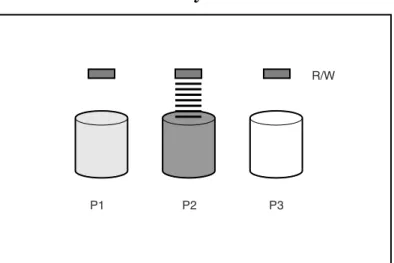
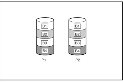
Connecting extra disk drives to a system increases the total storage capacity, but has no effect on the efficiency of read/write (R/W)
operations. Data can only be transferred to one physical disk at a time (see Figure 1-1).
Figure 1-1 Disk Drives Added to System
With an array controller installed in the system, the capacity of several physical disks can be combined into one or more virtual units called logical drives (also called logical volumes).
R/W
Logical Drives and Arrays
Chapter 1 16
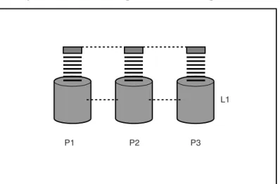
The read/write heads of all of the physical disks in a logical drive are active simultaneously, improving input/output (I/O) performance and reducing the total time required for data transfer (see Figure 1-2). Figure 1-2 Physical Disks Configured into a Logical Drive (L1)
L1
RAID Technology Overview
Logical Drives and Arrays
Chapter 1 17
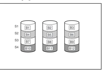
Because the read/write heads for each physical disk are active
simultaneously, the same amount of data is written to each disk during any given time interval. Each unit of data is called a block. The blocks form a set of data stripes spread evenly over all of the physical disks in a logical drive (see Figure 1-3).
Figure 1-3 Data Striping (S1-S4) of Data Blocks B1-B12
For data in the logical drive to be readable, the data block sequence must be the same in every stripe. This sequencing process is performed by the array controller (HP RAID160 SA), which sends the data blocks to the disk drive write heads in the correct order.
A natural consequence of the striping process is that each physical disk in a given logical drive will contain the same amount of data. If one physical disk has a larger capacity than other physical disks in the same logical drive, the extra capacity is wasted because it cannot be used by the logical drive.
The group of physical disks containing the logical drive is called a drive array (or just array). Since all of the physical disks in an array are commonly configured into just one logical drive, the term array is also often used as a synonym for logical drive.
Each logical drive is distributed over all of the physical disks within an array. A logical drive can also extend over more than one channel on the same controller, but it cannot extend over more than one controller.
S1 S2 S3 S4 B1 B4 B7 B2 B5 B8 B11 B10 B12 B6 B3 B9
Logical Drives and Arrays
Chapter 1 18
Disk failure, although rare, is potentially catastrophic. If a physical disk fails, the logical drive it is assigned to will fail, and all of the data on that logical drive will be lost.
To protect against data loss due to physical disk failure, logical drives can be configured with fault tolerance. The RAID configurations that are supported by the HP RAID160 SA controller are:
• RAID 0—Data Striping only (no fault tolerance) • RAID 1—Data Mirroring only (fault tolerant)
• RAID 1+0—Drive Mirroring and Striping (fault tolerant) • RAID 5—Distributed Data Guarding (fault tolerant) • RAID ADG—Advanced Data Guarding (fault tolerant)
For any configuration except RAID 0, further protection against data loss can be achieved by assigning a physical disk as an online spare (or hot spare). Spare disk drives contain no data and must be in the same array as the logical drive they are assigned to. Multiple spare disk drives can be assigned to a logical drive, limited only by the availability of unused physical disks in the array. When a spare disk drive is assigned to a logical drive, it can only serve as a spare for the logical drive it is assigned to. When a physical disk in the array fails, the controller automatically rebuilds the information that was originally on the failed disk, onto an online spare. The system is quickly restored to full
RAID-level data protection. In the unlikely event that another disk in the array fails while data is being rewritten to the spare, the logical drive may fail, depending on which RAID configuration is in use. See
RAID Technology Overview
HP RAID160 SA Controller Supported RAID Configurations
Chapter 1 19
HP RAID160 SA Controller Supported RAID
Configurations
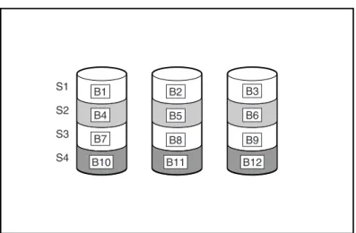
RAID 0—No Fault Tolerance
The RAID 0 configuration enhances performance with data striping, but there is no data redundancy to protect against data loss when a physical disk fails. RAID 0 is useful for rapid storage of large amounts of
non-critical data (for printing or image editing, for example), or when cost is the most important consideration (see Figure 1-4 on page 19). Figure 1-4 Data Striping (S1-S4) of Data Blocks B1-B12
Advantages
• Highest performance configuration for writes • Lowest cost per unit of data stored
• All disk capacity is used to store data (none needed for fault tolerance)
Disadvantages
• All data on the logical drive is lost if a physical disk fails
S1 S2
S3 S4
B1 B4 B7
B2
B5
B8 B11
B10 B12
B6 B3
HP RAID160 SA Controller Supported RAID Configurations
Chapter 1 20
• Cannot use an online spare
• Can only preserve data by backing it up to external disk drives
NOTE The original Berkeley RAID study only defined levels 1 through 5. RAID Level 0 was conceived later, but is not considered to be a “true” RAID, because it does not provide any fault tolerance.
RAID 1—Disk Drive Mirroring
In this configuration, only two physical disks are present in the array. Data is duplicated from one disk onto the other disk creating a mirrored pair of disk drives, but there is no striping of data (see Figure 1-5, “Disk Drive Mirroring of P1 onto P2 (RAID 1),”).
Figure 1-5 Disk Drive Mirroring of P1 onto P2 (RAID 1)
Advantages
• No data loss or interruption of service, if a disk fails • Fast read performance - data is available from either disk Disadvantages
• Cost is high - 50% of disk space is allocated for data protection
P1 P2
B1 B2
B3 B4
B1 B2
B3 B4
RAID Technology Overview
HP RAID160 SA Controller Supported RAID Configurations
Chapter 1 21
• Only 50% of total disk drive capacity is usable for data storage
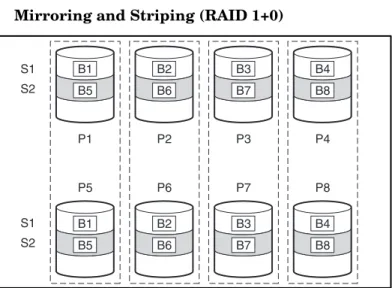
RAID 1+0—Disk Drive Mirroring and Striping
This configuration requires an array with four or more physical disks. The disks are mirrored in pairs and data blocks are striped across the mirrored pairs (see Figure 1-6, “Mirroring and Striping (RAID 1+0),” Figure 1-6 Mirroring and Striping (RAID 1+0)
In each mirrored pair, the physical disk that is not busy answering other requests answers any read request sent to the array (this behavior is called load balancing). If a physical disk fails, the remaining disk in the mirrored pair can still provide all the necessary data. Several disks in the array can fail without incurring data loss, as long as no two failed disks belong to the same mirrored pair.
This fault-tolerance method is useful when high performance and data protection are more important than the cost of physical disks.
Advantages
• Highest read and write performance of any fault-tolerant configuration
• No loss of data as long as none of failed disks are mirrored to another failed disk (up to half of the physical disks in the array can fail)
S1 S2 S1 S2 P1 P5 B5 B1 B1 B5 P2 P6 B6 B2 B2 B6 P3 P7 B7 B3 B3 B7 P4 P8 B8 B4 B4 B8
HP RAID160 SA Controller Supported RAID Configurations
Chapter 1 22
Disadvantages
• Expensive (many disks needed for fault tolerance)
• Only 50% of total disk drive capacity usable for data storage
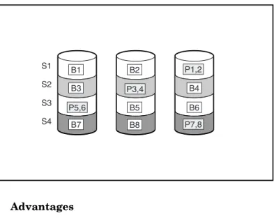
RAID 5—Distributed Data Guarding
RAID 5 employs a parity data formula. With this configuration, one block in each data stripe contains parity data that is calculated for each data block in that stripe. The blocks of parity data are distributed over the physical disks that make up the logical drive, with each physical disk having only one block of parity data (see Figure 1-7, “Distributed Data Guarding, Showing Parity Information (Px,y),”). When a physical disk fails, the data that was on the failed disk can be calculated from the data blocks on the remaining physical disks in the logical drive, by using the parity data for each stripe in that logical drive. This recovered data is usually written to an online spare in a process called a rebuild. This configuration is useful when cost, performance, and data availability are equally important.
Figure 1-7 Distributed Data Guarding, Showing Parity Information (Px,y)
Advantages
• High read performance
• No loss of data if one physical disk fails
S1 S2 S3 S4 B1 B3 P5,6 P3,4 P1,2 P7,8 B7 B2 B5 B8 B4 B6
RAID Technology Overview
HP RAID160 SA Controller Supported RAID Configurations
Chapter 1 23
• More disk drive capacity usable than with RAID 1+0—parity information only requires the storage space equivalent to one physical disk on the array
Disadvantages
• Relatively low write performance
• Loss of data if a second disk fails before data from the first failed disk is rebuilt
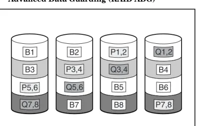
RAID ADG—Advanced Data Guarding
RAID ADG is similar to RAID 5 in that parity data is generated (and stored) to protect against data loss caused by physical disk failure. With RAID ADG, however, two different sets of parity data are generated for each data block on a stripe, then the two parity data blocks are stored on different physical disks allowing data to be preserved even if two
physical disks fail simultaneously. As can be seen in Figure 1-8, “Advanced Data Guarding (RAID ADG),” the two sets of parity data require as much storage capacity as the data blocks they correspond to on each stripe in a logical drive.
HP RAID160 SA Controller Supported RAID Configurations
Chapter 1 24
This method is most useful when data loss is unacceptable, but cost must also be minimized. The probability that data loss will occur when arrays are configured with RAID ADG is less than when they are configured with RAID 5 (see Appendix A, “Probability of Logical Drive Failure,” on page 133).
Figure 1-8 Advanced Data Guarding (RAID ADG)
Advantages
• High read performance
• High data availability—any two disks can fail without loss of critical data
• More disk drive capacity usable than with RAID 1+0—parity information requires only the storage space equivalent to two physical disks
Disadvantages
The only significant disadvantage of RAID ADG is a relatively low write performance (lower than RAID 5), due to the need for two sets of parity data.
B1
B3
P5,6
Q7,8
B2
B7 P3,4
Q5,6 B5
B8 P1,2
Q3,4 B4
B6
P7,8 Q1,2
RAID Technology Overview
Summary of RAID Methods
Chapter 1 25
Summary of RAID Methods
Table 1-1 summarizes the important features of the different RAID configurations that are supported by the HP RAID160 SA controller. The decision chart in Table 1-2 on page 26. may help with determining which option is best for your computing environment.
Table 1-1 Summary of RAID Methods
RAID 0 RAID 1 RAID1+0 RAID 5 RAID ADG
Alternative name Striping (no fault tolerance)
Mirroring Mirroring and Striping Distributed Data Guarding Advanced Data Guarding Usable disk drive
space*
100% 50% 50% 67% to 93% 50% to 96%
Usable disk drive space formula
n n/2 n/2 (n-1)/n (n-2)/n
Minimum number of physical disks
1 2 4 3 4
Tolerates failure of one physical disk?
No Yes Yes Yes Yes
Tolerates simultaneous failure of more than one physical disk?
No No Only if no two failed disks are in a mirrored pair
No Yes
Read performance High High High High High
Write performance High Medium Medium Low Low
Relative cost Low High High Medium Medium
*Values for usable disk drive space are calculated with these assumptions: (1) All physical disks in the array have the same capacity; (2) Online spares are not used; (3) No more than 14 physical disks are used per array for RAID 5; (4) No more than 56 disks are used with RAID ADG.
Choosing a RAID Method
Chapter 1 26
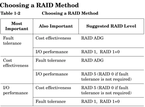
Choosing a RAID Method
Table 1-2 Choosing a RAID Method
Most
Important Also Important Suggested RAID Level Fault
tolerance
Cost effectiveness RAID ADG
I/O performance RAID 1, RAID 1+0 Cost
effectiveness
Fault tolerance RAID ADG
I/O performance RAID 5 (RAID 0 if fault tolerance is not required) I/O
performance
Cost effectiveness RAID 5 (RAID 0 if fault tolerance is not required) Fault tolerance RAID 1, RAID 1+0
Chapter 2 27
2
RAID160 SA Controller
Overview
This chapter contains the following sections providing an overview of the RAID160 SA controller features and functionality:
Board Components and Features
Chapter 2 28
Board Components and Features
The RAID160 SA controller has four Wide Ultra160 SCSI channels and 256 MB of cache.
Figure 2-1 HP A7143A RAID160 SA controller
Table 2-1 Hardware Overview
Item Description
1 Two internal 68-pin Wide SCSI connectors (channel 1 nearer the bracket, channel 2 nearer the board center). These internal
connectors are not supported on the HP A7143A RAID160 SA controller.
2 Four external (VHDCI) connectors (channels 1 and 3 nearer the main board)
3 Array accelerator cache 1
2
RAID160 SA Controller Overview
Board Components and Features
Chapter 2 29
NOTE Ports 1 and 2 each have two connectors (one internal and one external). However, only one connector can be used per channel at any given time. Ports 3 and 4 can be used only for external disk drives. The internal
connectors are not supported on the HP A7143A RAID160 SA controller.
Figure 2-2 Array Accelerator Cache with Batteries
For detailed controller board specifications, refer to Appendix B, “Controller Specifications”.
Overview of Controller Features
• Four Wide Ultra160 SCSI channels, supporting up to 56 disk drives (4 channels, 14 drives per channel)
• Support for HP-UX 11i v1 Operating System (64-bit only) • Backward compatibility with Wide Ultra2 devices • Removable array accelerator
• 64-bit, 33/66-MHz PCI system interface • Other features supported:
— RAID 0 (striping)
Board Components and Features
Chapter 2 30
— vPars (HP-UX Virtual Partitions) — Ignite UX
— Hot-pluggable disk drives — Drive movement
— Adjustable stripe size — S.M.A.R.T. disk drives
— Multiple online spares per array — Background initialization
Overview of Array Accelerator Features
The array accelerator is a high performance, battery-backed, 100-MHz SDRAM DIMM cache module.
The RAID160 SA controller uses cache to store read data from the disk drives. The system can later access this read data. The controller firmware uses the “read-ahead” and “most recently used” caching algorithms.
The RAID160 SA controller also uses cache to complete drive write operations more quickly. This use of the cache has further performance benefits:
• If the system requires data that still resides in the write cache, the controller delivers this data from the cache. This process is quicker than delivering the data from a drive.
• If the system writes new data to the same location, the controller overwrites the cache contents. This eliminates a drive write operation.
• If the system performs a RAID 1 procedure, the controller gets mirrored data from the cache instead of from host memory.
• If the system performs a RAID 5 procedure, the write cache collects enough data blocks from several write accesses to carry out a full stripe write to the disk drives. This operation eliminates the need to calculate and update parity information each time a data block is written to the drive.
RAID160 SA Controller Overview
Board Components and Features
Chapter 2 31
• Cache capacity of 256-MB with 224-MB usable cache (32 MB of the cache is used for transfer buffer).
• Error checking and correcting (ECC) memory, providing single-bit data correction.
Batteries
The array accelerator cache has two NiMH battery packs. Figure 2-3 Battery Packs
If a power outage occurs, the batteries will preserve cashed data for up to 72 hours. When power is restored to the system, an initialization process will write the preserved data to the disk drives.
The batteries are continuously recharged using a trickle-charging process whenever the system power is on.
Board Components and Features
Chapter 2 32
IMPORTANT The batteries on a new RAID160 SA controller may have a low charge when the controller board is first installed. No action is required on your part, since the internal circuitry automatically recharges the batteries and enables the cache. The recharge process takes less than four hours.
The controller will function properly during this time, but without the performance advantage of the array accelerator. When the batteries are
charged to an acceptable capacity, the array accelerator is automatically enabled.
PCI System Interface
RAID160 SA controller interfaces with the system through a high-performance 64-bit PCI bus that:
• Runs at 66 MHz
• Provides a high-speed path (up to 528 MB/s) between the system board and the controller
• Includes two parity protection signals
The RAID160 SA controller is a PCI Bus Master device conforming to Rev. 2.2 of the PCI Local Bus Specification. As a bus master device, it takes control of the PCI bus during high-speed transfers, freeing the system processor to handle application processing or other types of tasks. For maximum performance, HP recommends that you use only 66-MHz devices on any given 66-MHz PCI bus. Combining 66-MHz and 33-MHz devices on a PCI bus will decrease the overall bandwidth to 33-MHz speeds.
SCSI Support
The RAID160 SA controller supports disk drives that conform to Wide Ultra160 and Wide Ultra2 standards. Although Wide Ultra2 devices operate at a different maximum speed from Wide Ultra160 devices, operating speeds are unaffected if they are connected to the same SCSI bus because they both use low voltage differential (LVD) signaling.
RAID160 SA Controller Overview
Board Components and Features
Chapter 2 33
Fault Management Features
The RAID160 SA controller and the HP-UX operating system support several fault management and data reliability features that minimize the impact of disk drive defects on your system.
• Auto-Reliability Monitoring (ARM) is a firmware process that operates in the background scanning physical disks for bad sectors in fault-tolerant logical drives. ARM also verifies the consistency of parity data in logical drives that are using RAID 5 or RAID ADG. This process assures that you can recover all data successfully if a disk failure occurs in the future. ARM operates only when you select a fault-tolerant configuration (RAID 1 or higher).
• Dynamic sector repair by the RAID160 SA controller
automatically remaps any sectors that have media faults (detected either during normal operation or by auto reliability monitoring). • S.M.A.R.T. is an industry-standard diagnostic and failure-prediction
feature of physical disks, developed by HP in collaboration with the disk drive industry. It monitors several factors that can be used to predict imminent physical disk failure due to mechanical causes. Such factors include the condition of the read/write head, the seek error rate, and the spin-up time. When a threshold value is exceeded for one of these factors, the disk sends an alert that failure is
imminent. Thus, the user can back up data and replace the disk drive before failure occurs.
NOTE An online spare does not become active and start rebuilding when the imminent failure alert is sent, because the degraded disk has not actually failed yet and is still online. The online spare is activated only after a disk in the array has failed.
• Drive failure alert features cause an alert message to be sent to Event Monitoring Services (EMS) when physical disk or logical drive failure occurs.
• Interim data recovery occurs if a disk fails in fault-tolerant configurations (RAID level 1 or higher).
Board Components and Features
Chapter 2 34
If a physical disk fails in RAID 1, RAID 1+0, RAID 5, or ADG, the system will still process I/O requests, but at a reduced performance level. Replace the failed physical disk as soon as possible to restore performance and full fault tolerance for the logical drive it belongs to. The risk of continuing operations without replacing a failed physical disk varies depending on the RAID level that has been configured: — RAID 1: If RAID 1 is configured, the result will be a single
mirrored pair of disks. If one physical disk fails, the remaining disk in the mirrored pair can still provide all of the data.
— RAID 1+0: A RAID 1+0 configuration will have a minimum of 4 physical disks, and the total number of physical disks will be divisible by 2 (to support mirrored pairs). In RAID 1+0, if a physical disk fails, the remaining disk in any mirrored pair will still provide all of the data that was on the failed disk. In fact, several physical disks in an array can fail without incurring data loss, as long as no two failed physical disks belong to the same mirrored pair.
— RAID 5: If a physical disk fails in a RAID 5 configuration, data is recovered via a parity formula and is typically written to an on-line spare physical disk. If a second physical disk fails before the data from the initial physical disk failure has been rebuilt on the on-line spare disk, the logical drive will fail and data will be lost.
— ADG: Similar to RAID 5, ADG also relies on a parity scheme to rebuild data if a physical disk fails. However, in an ADG configuration the parity data is duplicated on two different physical disks. As a result, ADG can support the failure of two physical disks without data loss.
For a more detailed description of the RAID levels supported by the HP A7143A RAID160 SA controller see Chapter 1, “RAID
Technology Overview,” on page 11.
For detailed information on the probability of logical drive failure, see Appendix A, “Probability of Logical Drive Failure,” on page 133. • Recovery ROM is a redundancy feature that ensures continuous
system availability by providing a backup ROM. This feature protects against corruption of a ROM image (caused, for example, by power fluctuation during ROM upgrade). If corruption occurs, the server automatically restarts using the remaining good copy of the
RAID160 SA Controller Overview
Board Components and Features
Chapter 2 35
ROM image. When you upgrade the ROM, the inactive image (the one not being used by the system) is upgraded. There is not normally any noticeable difference in operation. When you use Recovery ROM for the first time, however, both ROM images are upgraded, causing a boot delay of about 60 seconds.
Board Components and Features
Chapter 2 36
Chapter 3 45
3
Installation Overview
This chapter provides information to help you plan the installation and configuration of the RAID160 SA controller.
Chapter 3 46
NOTE Complete Smart Array documentation (including the Smart Array Support matrix) is available on http://www.docs.hp.com under the I/O Cards and Networking Software section in the Smart Array (RAID) category.
NOTE To view a detailed list of support accessories visit the system
Installation Overview
Overview of Installation Steps
Chapter 3 47
Overview of Installation Steps
Installation steps for the RAID160 SA controller are as follows: Step 1. Plan your disk configurations (see Chapter 1, “RAID Technology
Overview,” on page 11).
Step 2. Check the installation prerequisites (see “Installation Prerequisites for the RAID160 SA Controller” on page 49).
Step 3. Install the software: See “Locating Software for the RAID160 SA Controller” on page 52 and “Installing Software for the RAID160 SA Controller” on page 53.
Step 4. Install the controller: See “Installing the RAID160 SA Controller
Hardware (Offline)” on page 57 or “Online Addition and Replacement” on page 59.
Step 5. Upgrade the controller firmware, if necessary: See “RAID160 SA Controller Firmware” on page 74).
Step 6. Connect the JBODs (see “Connecting the Cables and the StorageWorks‘ Disk Enclosures” on page 66).
Step 7. Label the cables connecting the JBODs to the controller (see “Labeling the Cables” on page 69).
Planning Disk Configurations
Chapter 3 48
Planning Disk Configurations
If you have not determined the RAID level you want to configure for your application, see Chapter 1, “RAID Technology Overview,” on page 11 for details on RAID160 SA supported RAID levels.
RAID160 SA Array Configuration Guidelines
Please keep in mind the following configuration limits for the RAID160 SA controller:
• The maximum number of physical disks per channel is 14.
• The maximum number of arrays per controller is 8. (An array is a grouping of physical disks.)
Installation Overview
Installation Prerequisites for the RAID160 SA Controller
Chapter 3 49
Installation Prerequisites for the RAID160 SA
Controller
Before installing the RAID160 SA controller, check to make sure the following hardware and software prerequisites have been met:
✓ Read the RAID160 SA controller Release Note, so you can check for any known problems, required patches, or other information you need for installation.
✓ Plan your disk configurations (see “Planning Disk Configurations” on page 48).
✓ Make sure you have super-user (root) privileges.
✓ Confirm your HP-UX operating system version is supported by the RAID160 SA controller. To determine the HP-UX version you are using, enter this command:
uname -a
See the RAID160 SA controller Release Note or Table 3-1, “HP A7143A Support Matrix,” on page 50, for information about the required operating system versions.
✓ Make sure the /usr/sbin, /sbin, and /usr/bin directories are in your PATH statement. To do this, log in as root and enter this command:
echo $PATH
CAUTION If any data currently exists on the StorageWorks disk enclosure, back it up if you want to retain the file system and the data. Configuring logical drives will destroy any data on the disks.
When you are sure you have met the installation prerequisites, go to Chapter 4, “Installing the RAID160 SA Controller,” on page 51.
Installation Prerequisites for the RAID160 SA Controller
Chapter 3 50
HP A7143A RAID160 SA Controller Support Matrix
Table 3-1 HP A7143A Support Matrix
Supported Systems HP-UX Release Software Bundle Name controller Firmware Level OLAR Support Boot Support rp24xx A400 A500
11i, 64-bit RAID-01 version 3.32 No Yes rp54xx Excluding: L1000 (Product Number A5576A) L2000 (Product Number A5191A)
11i, 64-bit RAID-01 version 3.32 Yes Yes rp7400 Excluding: N4000 Revision A (Product Number A3639A) N4000 Revision B (Product Number A3639B)
11i, 64-bit RAID-01 version 3.32
Yes Yes
rp7410 11i, 64-bit RAID-01 version 3.32
Chapter 4 51
4
Installing the RAID160 SA
Controller
This chapter contains the following sections detailing hardware, software, and firmware installation for the RAID160 SA controller:
Locating Software for the RAID160 SA Controller
Chapter 4 52
Locating Software for the RAID160 SA
Controller
The drivers, utilities and manpages for the RAID160 SA controller are located at the HP Software Depot.
• Go to http://www.software.hp.com
• Search for “A7143A” to find the “pci 4-channel raid160 sa scsi controller”
• Click on “receive for free”
• Fill out the free product registration form and click on “next”
• Look for “Download Software” and click on “A7143A_11_11_01.depot” to download the drivers, utilities and manpages for the RAID160 SA controller
• In the “Documents” column next to the “Download Software” column, click on “Installation Instructions” to download instructions for using the Software Distributor tool to install the drivers, utilities and manpages for the RAID160 SA controller
Installing the RAID160 SA Controller
Installing Software for the RAID160 SA Controller
Chapter 4 53
Installing Software for the RAID160 SA
Controller
The drivers, utilities and manpages for the RAID160 SA controller are contained in the RAID-01 bundle located in the “pci 4-channel raid160 sa scsi controller” depot, see “Locating Software for the RAID160 SA Controller”. They can be installed using the Software Distributor (SD). The SD is a tool for installing software on HP-UX host systems. The SD can also be used to remove software from HP-UX host systems.
The instructions for using the SD to install or remove the drivers, utilities and manpages for the RAID160 SA controller can be downloaded at the HP Software Depot, see “Locating Software for the RAID160 SA Controller”.
The RAID-01 bundle is composed of several files that will be copied to the appropriate directories on the host system.
The SD will add the following files to an HP-UX host configuration: • /usr/conf/lib/libciss.a
This is the library of 64-bit object modules that must be linked into the HP-UX kernel
• /usr/conf/lib/ciss_dbg.o
This is the 64-bit debug object module that must be linked into the HP-UX kernel
• /usr/conf/master.d/ciss This is the master file • /opt/raidsa/bin/sautil
This is the support tool. sautil is an abbreviation for “Smart Array Support Utility”
Installing Software for the RAID160 SA Controller
Chapter 4 54
• /opt/raidsa/bin/saconfig
This is the command line configuration tool. saconfig is an abbreviation for “Smart Array Configuration Utility”
• /sbin/rc2.d/S900ciss
S900ciss (Run-2; start script) is a symbolic link pointing to /sbin/init.d/ciss
• /sbin/init.d/ciss
“ciss” is a startup script to make a device file for RAID160 • /usr/sbin/olrad.d/ciss
This is the script for OLAR • /usr/share/man/man1m.Z
The manpages for sautil and saconfig are located here • /opt/raidsa/bin/MAXWELL332.BIN
Installing the RAID160 SA Controller
Preparing for RAID160 SA Controller Installation
Chapter 4 55
Preparing for RAID160 SA Controller
Installation
Before installing a RAID160 SA controller in a server, backup all data. This step is mandatory if the disks were not previously configured on a RAID160 SA controller, because the data format will not be recognized and the existing data will not be preserved.
Also, if you are connecting non-arrayed SCSI disk drives to a RAID160 SA controller, you must backup all data, because data is not preserved when RAID controllers are connected to non-arrayed disk drives.
NOTE If your server supports Online Addition and Replacement (OLAR) of the RAID160 SA controller and you plan to do an online installation, see “Online Addition and Replacement” on page 59. See the Table 3-1, “HP A7143A Support Matrix,” on page 50, to find out if your server supports OLAR.
To prepare a server that does not support OLAR, or if you would prefer to install the RAID160 SA controller offline:
1. Close all applications. 2. Power down the server.
3. Power down any peripheral devices that are attached to the server. 4. Unplug the AC power cord from the outlet, and then from the server.
CAUTION In systems using external data storage, be sure that the server is the first unit powered down and the last unit to be powered back up. Doing this ensures that the system will not erroneously mark the disk drives as “failed”.
Preparing for RAID160 SA Controller Installation
Chapter 4 56
WARNING To reduce the risk of personal injury or damage to the equipment, consult the safety information and user
documentation provided with your server before attempting installation.
Many computers are capable of producing energy levels that are considered hazardous. These computers are intended to be serviced by qualified personnel trained to deal with those hazards. Do not remove enclosures or attempt to bypass any interlocks that may be provided for the purpose of removing these hazardous conditions.
CAUTION Electrostatic discharge (ESD) can damage electronic components. Be sure that you are properly grounded before continuing the installation procedure. See Appendix D, “Electrostatic Discharge,” on page 159, for ESD information.
The RAID160 SA controller contains electronic components that can easily be damaged by small amounts of static electricity. To avoid damage, follow these guidelines:
• Store the controller in its antistatic plastic bag until you are ready to install it
• Work in a static-free area, if possible
• Handle the controller only by the edges. Do not touch electronic components or electrical traces
• If you must lay the controller down, place it on a non-conductive mat or surface
Before beginning installation, and without removing the RAID160 SA controller from its antistatic bag, inspect the controller for any signs of obvious damage, such as chipped or loose components. Contact HP if the controller is damaged.
Installing the RAID160 SA Controller
Installing the RAID160 SA Controller Hardware (Offline)
Chapter 4 57
Installing the RAID160 SA Controller
Hardware (Offline)
1. Disconnect any peripheral devices from the server. 2. Remove or open the access panel on the server.
3. Select an available 66-MHz PCI slot. Slots that use a 64-bit interface may provide higher performance.
4. Remove the slot cover or open the hot-plug latch. Save the retaining screw, if one is present.
5. Slide the controller board along the slot alignment guide. Figure 4-1 Installing the HP A7143A RAID160 SA controller
NOTE Your server may look slightly different from the one illustrated
6. Press the controller board firmly into the slot so the contacts on the board edge are properly seated in the system board connector. 7. Secure the board in place with the hot-plug latch or retaining screw.
Installing the RAID160 SA Controller Hardware (Offline)
Chapter 4 58
8. Continue by following the instructions given in “Connecting the Cables and the StorageWorks‘ Disk Enclosures” on page 66“.
Installing the RAID160 SA Controller
Online Addition and Replacement
Chapter 4 59
Online Addition and Replacement
Online Addition and Replacement (OLAR) allows the RAID160 SA controller to be added online to HP-UX systems that support OLAR, without having to reboot. If the OLAR feature is used, it will not be necessary to completely shut down and then reboot the system to add or replace a RAID160 SA controller. System hardware uses per-slot power control combined with HP-UX OLAR utilities, to enable online addition or replacement of RAID160 SA controllers, without adversely affecting other system components.
You can add or replace a RAID160 SA controller in an HP-UX system that supports OLAR,by using the SAM utility to invoke the OLAR script.
If you are using SAM to online add or replace a controller, SAM will intervene and provide warnings to minimize the chance that you will perform an OLAR procedure that will adversely affect your HP-UX system.
IMPORTANT When using OLAR to add or replace a RAID160 SA controller, it is important to pay attention to the warning messages that will be displayed.
It is necessary to remove the SCSI cables from a RAID160 SA controller that is about to be online replaced, before the PCI slot is powered off. It is necessary to wait until power has been restored to the PCI slot, before the SCSI cables are connected to an add-in or replacement RAID160 SA controller.
If the SCSI cables are removed, or connected, to the RAID160 SA controller while the PCI slot is powered off, the OLAR procedure will have to be repeated. See “RAID160 SA Controller OLAR Error Recovery” on page 62.
During a RAID160 SA controller replacement operation, SAM performs a Critical Resource Analysis (CRA), which checks all channels on the target controller for critical resources that would be temporarily unavailable, while the controller is shut down. After completing the
Online Addition and Replacement
Chapter 4 60
CRA, SAM presents the options available to you. If critical resources will be affected by the OLAR procedure, you will have the option to replace the controller when the system is offline.
IMPORTANT In many cases, other controllers (host bus adapters) and slots within the system are dependent on the target controller. For example, if the target controller has multiple-channels (the RAID160 SA controller has 4 channels), suspending or deleting drivers for the target PCI slot also suspends individual drivers for the multiple hardware paths on the controller installed in that PCI slot.
For detailed instructions and information on using the OLAR feature, see, Managing PCI Cards with OLAR, which is the 2nd chapter of the
Configuring HP-UX for Peripherals book, Part Number B2355-90698.
This document can be viewed or downloaded at http://www.docs.hp.com, or a hard copy can be ordered from HP.
For detailed information about using SAM, see Using System
Administration Manager (SAM). This document can be viewed or
downloaded at http://www.docs.hp.com, or a hard copy can be ordered from HP.
Installing the RAID160 SA Controller
Online Installation of the RAID160 SA Controller
Chapter 4 61
Online Installation of the RAID160 SA
Controller
If your system has one or more slots that support OLAR—and you want to use OLAR to install the controller in one of those slots—follow these steps:
Step 1. Be sure version B.11.11.01 or later of the ciss driver (RAID160 SA software) is installed on your system. See “Locating Software for the RAID160 SA Controller” on page 52.
Step 2. Install the RAID160 SA controller in your HP-UX system according to the procedure described in the Managing PCI Cards with OLAR, which is the 2nd chapter of the Configuring HP-UX for Peripherals book, Part Number B2355-90698. This document can be viewed or downloaded at http://www.docs.hp.com, or a hard copy can be ordered from HP.
TIP To improve performance, install the RAID160 SA controller in a non-shared PCI slot running at PCI 2X speed or greater.
IMPORTANT When using OLAR to add or replace a RAID160 SA controller, it is important to pay attention to the warning messages that will be displayed.
It is necessary to remove the SCSI cables from a RAID160 SA controller that is about to be online replaced, before the PCI slot is powered off. It is necessary to wait until power has been restored to the PCI slot, before the SCSI cables are connected to an add-in or replacement RAID160 SA controller.
If the SCSI cables are removed, or connected, to the RAID160 SA controller while the PCI slot is powered off, the OLAR procedure will have to be repeated. See “RAID160 SA Controller OLAR Error Recovery” on page 62.
RAID160 SA Controller OLAR Error Recovery
Chapter 4 62
RAID160 SA Controller OLAR Error Recovery
This section explains how to recover:• If you are attempting an online addition of a RAID160 SA controller and the SCSI cables are connected before the PCI slot is powered on • If you are attempting an online replacement of a RAID160 SA
Controller and the SCSI cable(s) are not disconnected, before the PCI slot is powered off
• If you are attempting an online replacement of a RAID160 SA Controller and the SCSI cable(s) are reconnected, before the PCI slot is powered on again
In any of these circumstances, an OLAR error message will be displayed (see Figure 4-4, “First Error Message,”).
Online Addition Error
If you are attempting an online addition of a RAID160 SA controller and the SCSI cable(s) are connected to the add-in controller, before power is restored to the PCI slot, an OLAR error message will appear on your monitor (see Figure 4-4, “First Error Message,”).
Proceed to “OLAR Error Recovery” on page 64.
Online Replacement Error
A message will appear during online replacement warning you when to disconnect the SCSI cables from the A7143A adapter (RAID160 SA controller) you are replacing. See Figure 4-2, “SCSI Cable Disconnect Warning,”:
Installing the RAID160 SA Controller
RAID160 SA Controller OLAR Error Recovery
Chapter 4 63
Figure 4-2 SCSI Cable Disconnect Warning
If you continue the online replacement according to the instructions, once the replacement controller has been installed in the PCI slot, the following message will appear (see Figure 4-3, “SCSI Cable Reconnect Note,”):
Figure 4-3 SCSI Cable Reconnect Note
At this point you reset the RAID160 SA controller and the online replacement is complete.
If the error message in Figure 4-4 appears, before the online replacement procedure is completed, proceed to the next section “OLAR Error
RAID160 SA Controller OLAR Error Recovery
Chapter 4 64
OLAR Error Recovery
If the SCSI cables are disconnected from, or connected to, a controller after the PCI slot is powered off, the OLAR procedure will fail and the following message will appear (see Figure 4-4, “First Error Message,”): Figure 4-4 First Error Message
At this point the controller is suspended and will remain suspended, unless the following steps are followed:
1. Click “OK” on the first error message (see Figure 4-4, “First Error Message,”)
2. The following message will appear (see Figure 4-5, “Second Error Message,”).
Installing the RAID160 SA Controller
RAID160 SA Controller OLAR Error Recovery
Chapter 4 65
3. Now, disconnect the SCSI cable(s) from the controller and click “YES”. The following message will be appear (see Figure 4-6, “SCSI Cable Reconnect Note,”):
Figure 4-6 SCSI Cable Reconnect Note
4. Now connect the SCSI cable(s) to the controller, click “OK”, and run sautil /dev/cissxx reset_adapter. After the reset operation is completed, the controller will be operational.
Connecting the Cables and the StorageWorks‘ Disk Enclosures
Chapter 4 66
Connecting the Cables and the
StorageWorks
Disk Enclosures
• Each channel on the RAID160 SA controller supports up to 14 drives • Ports 1 and 2 each have two SCSI connectors, one for external
storage units and one for internal hard drives in the server
• The internal and external connectors on channel 1 cannot be used simultaneously
• The internal and external connectors on channel 2 cannot be used simultaneously
• Ports 3 and 4 can only be connected to external storage units
NOTE Currently the internal ports on the RAID160 SA controller are not supported.
Peripherals attached to any of the connectors must have a unique SCSI ID value in the range of 0 to 15 (except ID 7, which is reserved for controller use). The SCSI ID value determines the priority given to the device when it attempts to use the SCSI bus.
The supported HP StorageWorks disk enclosures automatically set the SCSI IDs for the physical disks they contain.
IMPORTANT To preserve an existing configuration when replacing an existing RAID160 SA controller with a different RAID160 SA controller, be certain to reconnect the SCSI cables to the same channels on the
replacement controller as the channels they had been connected to on the original controller, (channel 1 to channel 1, channel 2 to channel 2, and so on).
To prevent signal degradation, SCSI buses require termination on both ends. In HP servers and storage systems, the controller, SCSI cable, and backplane provide the required termination.
Installing the RAID160 SA Controller
Connecting the Cables and the StorageWorks‘ Disk Enclosures
Chapter 4 67
Supported StorageWorks Disc Enclosures
The RAID160 SA controller supports the following HP StorageWorks disc enclosures:
• StorageWorks 43xxT (Tower) Ships with one VHDCI to VHDCI 6-foot cable
• StorageWorks 4314R (Rack) Ships with one VHDCI to VHDCI 12-foot cable
• StorageWorks 4354R (Rack) Ships with two VHDCI to VHDCI 12-foot cables
External Cabling for HP Servers
All HP StorageWorks storage enclosure models include external SCSI cables. Check the connector type on your storage device to identify the cable type needed. See Figure 3-2 and Table 3-1 for details.
Figure 4-7 Identifying SCSI Cable Connectors
4 1
Connecting the Cables and the StorageWorks‘ Disk Enclosures
Chapter 4 68
Table 4-1 Cable Connector Descriptions (see Figure 3-2 above) Item Description
1 External 68-pin Wide 2 External offset VHDCI
3 Internal 50-pin narrow (Internal connections
are not supported on the RAID160 SA controller)
4 Internal 68-pin Wide (Internal connections are
not supported on the RAID160 SA controller)
Table 4-2 Supported External SCSI Cables for StorageWorks Enclosures
Cable Type Length Option Kit
Number
Cable Assembly Number
External Offset VHDCI to External Offset VHDCI
1.8 m / 6 ft. 341174-B21 313374-001
External Offset VHDCI to External Offset VHDCI
3.6 m / 12 ft. 341175-B21 313374-002
External Offset VHDCI to External Offset VHDCI
7.2 m / 24 ft. 164604-B21 313374-004
External Offset VHDCI to External Offset VHDCI
11.7 m / 39 ft. 150214-B21 313374-005
External Offset VHDCI to External Wide
1.8 m / 6 ft. 341176-B21 313375-001
External Offset VHDCI to External Wide
3.6 m / 12 ft. 341177-B21 313375-002
Installing the RAID160 SA Controller
Connecting the Cables and the StorageWorks‘ Disk Enclosures
Chapter 4 69
NOTE IMPORTANT: Offset VHDCI cables must be used with the RAID160 SA controller. Early versions of the VHDCI cables do not accommodate side-by-side connection to the RAID160 SA controller. If your storage enclosure did not include the Offset VHDCI cables, you may need to order them. See Table 4-2 above, for part numbers.
Up to four SCSI ports on the RAID160 SA controller are available for connection to external storage devices.
1. On the rear of the server, connect the cable to the VHDCI connector on the Smart Array controller, and then tighten the lock screws on the cable connector.
2. Attach the other end of the cable to the HP StorageWorks storage enclosure, and then tighten the lock screws on the cable connector. 3. Label the cables. See Labeling the Cables, below.
4. Replace the access panel and secure it with the thumbscrews, as required.
CAUTION Do not operate the server with the access panel removed for extended periods of time. This precaution is to protect thermally sensitive
components by ensuring the proper airflow through the server, and also to minimize personal contact with hazardous energy levels.
In systems using external data storage, be sure that the server is the first unit powered down and the last unit to be powered back up. Doing this ensures that the system will not erroneously mark the drives as “failed”.
Labeling the Cables
If the cables connecting the RAID controllers and the disk enclosures are switched, data could be corrupted. HP strongly recommends that each cable is labeled to show the following information:
✓ The controller’s slot number (this is stenciled on the system) ✓ The controller’s channel number
Connecting the Cables and the StorageWorks‘ Disk Enclosures
Chapter 4 70
✓ The StorageWorks disk enclosure the cable connects to (if there are multiple disk enclosures)
✓ The SCSI bus connection ID on the I/O module in the
Installing the RAID160 SA Controller
Verifying the Installation
Chapter 4 71
Verifying the Installation
After the system reboots, verify that the installation was successful by following these steps:
Step 1. Issue the swlist command: swlist
If the RAID160 SA controller is installed correctly, the generated output will look similar to this:
# swlist
# Initializing...
# Contacting target "hpfcs681"... #
# Target: hpfcs681:/ #
#
# Bundle(s): #
B3899BA B.11.11.06 HP C/ANSI C Developer’s Bundle for HP-UX 11.i (S700)
B3901BA B.11.11.04 HP C/ANSI C Developer’s Bundle for HP-UX 11.i (S800)
B7609BA A.04.00 Event Monitoring Service
BUNDLE11i B.11.11.0102.2 Required Patch Bundle for HP-UX 11i, February 2001
Base-VXVM B.03.20.1 Base VERITAS Volume Manager 3.2
for HP-UX
Verifying the Installation
Chapter 4 72
FDDI-00 B.11.11.02 PCI FDDI;Supptd HW=A3739A/A3739B;SW=J3626AA
FibrChanl-00 B.11.11.09 PCI/HSC FibreChannel;Supptd HW=A6684A,A6685A,A5158A,A6795A
GOLDAPPS11i B.11.11.0306.4 Gold Applications Patches for
HP-UX 11i, June 2003
GOLDBASE11i B.11.11.0306.4 Gold Base Patches for HP-UX 11i, June 2003
GigEther-00 B.11.11.14 PCI/HSC GigEther;Supptd HW=A4926A/A4929A/A4924A/A4925A;SW=J1642AA
GigEther-01 B.11.11.04 PCI GigEther;Supptd HW=A6794A/A6825A/A6847A
HPUX11i-OE B.11.11.0206 HP-UX 11i Operating Environment Component
HPUXBase64 B.11.11 HP-UX 64-bit Base OS HPUXBaseAux B.11.11.0206 HP-UX Base OS Auxiliary
HWEnable11i B.11.11.0306.4 Hardware Enablement Patches for HP-UX 11i, June 2003
OnlineDiag B.11.11.12.01 HPUX 11.11 Support Tools Bundle, Jun 2003
RAID-00 B.11.11.01 PCI RAID; Supptd HW=A5856A RAID-01 B.11.11.%08 RAID160; Supptd HW=A7143A perl B.5.6.1.C Perl Programming Language #
# Product(s) not contained in a Bundle: #
BullseyeCover11 6.1.6 HP-UX 11 LIF-LOAD B.11.11.07.11 HP LIF LOAD Tools