Release Notes
Version 6.0
Table of Contents
1
What's New in Release 6.0 ... 9
1.1
Supported Hardware Platforms ... 9
1.1.1 New Models and Hardware Configurations Introduced in this Release ... 9
1.1.2 Existing Hardware Platforms ... 9
1.1.3 Hardware Platforms No Longer Supported ... 10
1.2
SIP New Features ... 10
1.3
B2BUA Transcoding New Feature ... 29
1.3.1 SIP Network Definitions ... 29
1.3.1.1 Signaling Routing Domain (SRD) Entities ... 29
1.3.1.2 SIP Interfaces ... 30
1.3.1.3 Media Realm ... 31
1.3.2 SIP Dialog Initiation Process ... 32
1.3.2.1 Determining Source and Destination URL ... 33
1.3.2.2 Source IP Group Classification ... 33
1.3.2.3 IP-to-IP Routing ... 35
1.3.2.4 IP-to-IP Inbound and Outbound Manipulation ... 36
1.3.3 Media Handling ... 38
1.3.3.1 Media Anchoring without Transcoding (Transparent) ... 39
1.3.3.2 Media Anchoring with Transcoding ... 40
1.3.3.3 Transcoding Modes ... 41
1.4
Voice, RTP and RTCP New Features ... 42
1.5
Security New Features ... 44
1.6
PSTN New Features ... 45
1.7
Web New Features ... 54
1.8
SNMP New Features ... 56
1.9
Miscellaneous New Features ... 57
1.10
New Parameters ... 58
1.10.1 SIP Parameters ... 58
1.10.2 B2BUA Transcoding Parameters ... 71
1.10.3 Voice, RTP and RTCP Parameters ... 78
1.10.4 Security Parameters... 80
1.10.5 PSTN Parameters ... 82
1.10.6 Existing ini File Parameters Now Configurable in the Web ... 84
1.11
Modified Parameters ... 85
1.11.1 SIP Parameters ... 85
1.11.2 Voice, RTP and RTCP Parameters ... 95
1.11.3 PSTN Parameters ... 96
1.12
Obsolete Parameters ... 98
2
Supported Features ... 99
2.1
SIP Features ... 99
2.1.1 Supported SIP Features ... 99
2.1.2 Unsupported SIP Features ... 102
2.1.3 SIP Compliance Tables ... 103
2.1.3.1 SIP Functions ... 103
2.1.3.2 SIP Methods ... 103
2.1.3.3 SIP Headers ... 104
2.1.3.4 SDP Headers ... 106
Mediant 2000 & Mediant 3000
2.2
PSTN to SIP Interworking ... 111
2.2.1 Supported Interworking Features ... 111
2.2.2 Interworking Features Not Supported ... 112
2.3
DSP Firmware Templates ... 112
2.4
Template Mix Feature ... 116
2.5
Product Capability Comparison ... 117
3
Known Constraints ... 119
3.1
Voice, RTP and RTCP Constraints ... 119
3.2
Infrastructure Constraints ... 120
3.3
Networking Constraints ... 121
3.4
Security Constraints ... 121
3.5
High Availability Constraints... 121
3.6
PSTN Constraints ... 122
3.7
Web Constraints ... 123
3.8
SNMP Constraints ... 124
3.9
CLI Constraints ... 124
4
Resolved Constraints ... 125
4.1
Voice, RTP and RTCP Resolved Constraints ... 125
4.2
Web Resolved Constraints ... 125
4.3
SNMP Resolved Constraints... 125
5
Earlier Releases ... 127
List of Tables
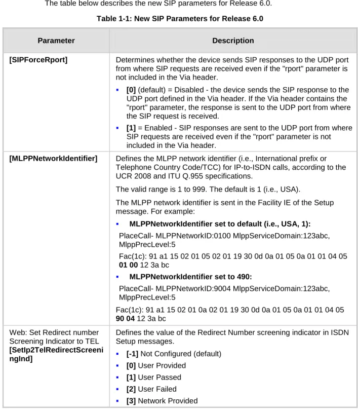
Table 1-1: New SIP Parameters for Release 6.0 ... 58
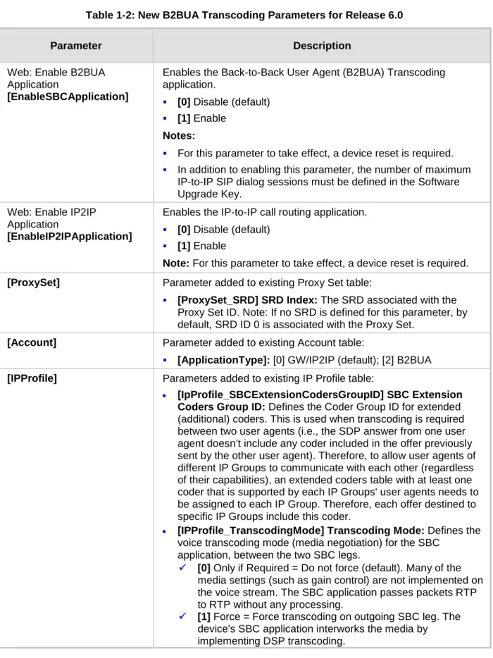
Table 1-2: New B2BUA Transcoding Parameters for Release 6.0 ... 71
Table 1-3: New Voice, RTP and RTCP Parameters for Release 6.0 ... 78
Table 1-4: New Security Parameters for Release 6.0 ... 80
Table 1-5: New PSTN Parameters for Release 6.0 ... 82
Table 1-6: ini File Parameters now Configurable in the Web Interface for Release 6.0 ... 84
Table 1-7: Modified SIP Parameters for Release 6.0 ... 85
Table 1-8: Modified Voice, RTP and RTCP Parameter for Release 6.0 ... 95
Table 1-9: Modified PSTN Parameter for Release 6.0 ... 96
Table 1-10: Obsolete Parameters ... 98
Table 2-1: Supported SIP Functions ... 103
Table 2-2: Supported SIP Methods ... 103
Table 2-3: Supported SIP Headers ... 104
Table 2-4: Supported SDP Headers ... 106
Table 2-5: Supported 1xx SIP Responses ... 107
Table 2-6: Supported 2xx SIP Responses ... 107
Table 2-7: Supported 3xx SIP Responses ... 108
Table 2-8: Supported 4xx SIP Responses ... 108
Table 2-9: Supported 5xx SIP Responses ... 110
Table 2-10: Supported 6xx SIP Responses... 110
Table 2-11: DSP Firmware Templates for Mediant 2000 ... 113
Table 2-12: DSP Firmware Templates for Mediant 3000 ... 114
Table 2-13: DSP Firmware Templates for Mediant 3000 16 E1 /21 T1 ... 115
Table 2-14: Template Mix Feature Channel Capacity ... 116
Table 2-15: Capability Comparison between Devices ... 117
Mediant 2000 & Mediant 3000
Notice
This document describes the release of the AudioCodes Mediant 2000 Voice-over-IP (VoIP) SIP media gateway (housing the TP-1610 blade) and Mediant 3000 VoIP SIP media gateway (housing the TP-6310 or TP-8410 TrunkPack (TP) SIP cPCI blades)
Information contained in this document is believed to be accurate and reliable at the time of printing. However, due to ongoing product improvements and revisions, AudioCodes cannot guarantee accuracy of printed material after the Date Published nor can it accept responsibility for errors or omissions. Updates to this document and other documents can be viewed by registered customers at
.
This document is subject to change without notice. © Copyright 2010 AudioCodes Ltd. All rights reserved.
Date Published: February-03-2010
Trademarks
AudioCodes, AC, AudioCoded, Ardito, CTI2, CTI², CTI Squared, HD VoIP, HD VoIP Sounds Better, InTouch, IPmedia, Mediant, MediaPack, NetCoder, Netrake, Nuera, Open Solutions Network, OSN, Stretto, TrunkPack, VMAS, VoicePacketizer, VoIPerfect, VoIPerfectHD, What’s Inside Matters, Your Gateway To VoIP and 3GX are trademarks or registered trademarks of AudioCodes Limited. All other products or trademarks are property of their respective owners. Product specifications are subject to change without notice.
WEEE EU Directive
Pursuant to the WEEE EU Directive, electronic and electrical waste must not be disposed of with unsorted waste. Please contact your local recycling authority for disposal of this product.
Customer Support
Customer technical support and service are provided by AudioCodes’ Distributors, Partners, and Resellers from whom the product was purchased. For Customer support for products purchased directly from AudioCodes, contact
Abbreviations and Terminology
Each abbreviation, unless widely used, is spelled out in full when first used. Only industry-standard terms are used throughout this manual. Hexadecimal notation is indicated by 0x preceding the number.
Mediant 2000 & Mediant 3000
Related Documentation
Document Name Product Reference Manual for SIP CPE Devices
Mediant 2000 SIP Installation Manual Mediant 2000 SIP User's Manual Mediant 3000 SIP User's Manual
Mediant 3000 & IPmedia 3000 SIP-MGCP-MEGACO Installation Manual CPE SIP Configuration Guide for IP Voice Mail
Notes:Throughout this manual, unless otherwise specified, the term device refers to the Mediant 2000 and Mediant 3000 media gateways.
1
What's New in Release 6.0
Note: This document uses a one-row table with check boxes convention to indicate the products for which each feature is applicable. Only the products with marked check boxes are applicable to the feature. For example, the table below indicates that the feature is applicable only to Mediant 3000 High Availability (HA) housing the TP-6310.
Mediant 2000 Mediant 3000 with TP-6310 Mediant 3000 HA with TP-6310 Mediant 3000 with TP-8410 Mediant 3000 HA with TP-8410
1.1
Supported Hardware Platforms
1.1.1
New Models and Hardware Configurations Introduced in this
Release
Not applicable.
1.1.2
Existing Hardware Platforms
The following existing hardware platforms are supported in this release:
•
Mediant 3000 system: 2U carrier-grade chassis, supporting multiple configuration options of VoP cPCI blades:
•
Mediant 3000 hosting a single TP-8410 blade, providing 16 E1/ 21 T1 PSTN interfaces.
•
Mediant 3000 hosting a single TP-8410 blade, providing up to 63 E1/ 84 T1 PSTN interfaces.
•
Mediant 3000 hosting two TP-8410 blades for 1+1 High Availability (HA), providing up to 16 E1/ 21 T1 PSTN interfaces.
•
Mediant 3000 hosting two TP-8410 blades for 1+1 HA, providing up to 63 E1/ 84 T1 PSTN interfaces.
•
Mediant 3000 hosting a single TP-6310 blade, providing SONET/SDH or T3 PSTN interfaces.
•
Mediant 3000 hosting two TP-6310 blades for 1+1 HA, providing SONET/SDH or T3 PSTN interfaces.
•
Mediant 3000 hosting a single TP-8410 blade providing 16 E1/ 21 T1 PSTN interfaces with an integrated CPU (Intel Pentium) blade (M3K-ICPU-1), hosting third-party applications (such as SS7 GWC).
Mediant 3000 hosting a single TP-8410 blade providing up to 63 E1/ 84 T1 PSTN interfaces with an integrated CPU (Intel Pentium) blade (M3K-ICPU-1), hosting third-party applications (such as SS7 GWC).
Mediant 2000 system: 1U chassis hosting a TP-1610 cPCI blade with E1/T1 interfaces.
Mediant 2000 & Mediant 3000
1.1.3
Hardware Platforms No Longer Supported
Not applicable.
1.2
SIP New Features
The device supports the following new SIP features:
1. Sending SIP Response to UDP Port from where SIP Request Received regardless of "rport" Parameter:
Mediant 2000 Mediant 3000 with TP-6310 Mediant 3000 HA with TP-6310 Mediant 3000 with TP-8410 Mediant 3000 HA with TP-8410
In previous releases, the device sent SIP responses to the UDP port defined in the SIP Via header. If the Via header contained the "rport" parameter, the device sent the response to the UDP port from where the SIP request was received. In this release, the device can be configured (using the new parameter, SIPForceRport) to send SIP responses to the UDP port from where the SIP request was received even if the "rport" parameter is not received in the Via header.
Relevant parameter: SIPForceRport. 2. Maximum Proxy Sets Increased to 10:
Mediant 2000 Mediant 3000 with TP-6310 Mediant 3000 HA with TP-6310 Mediant 3000 with TP-8410 Mediant 3000 HA with TP-8410
The device now allows you to configure up to 10 Proxy Sets (compared to only 6 in previous releases). These are configured in the 'Proxy Sets' table (ProxySet). Relevant Parameter: ProxySet.
3. Offered Coders Increased to 10:
Mediant 2000 Mediant 3000 with TP-6310 Mediant 3000 HA with TP-6310 Mediant 3000 with TP-8410 Mediant 3000 HA with TP-8410
The device now supports the configuration of up to 10 coders (compared to only 5 in the previous release) for offering the remote end. This also applies to Coder Groups, where up to 10 coders can now be defined per Coder Group (compared to only 5 in the previous release).
In addition, a new parameter, CodersGroup now replaces the CoderName parameter (from previous versions). This new parameter supports backward compatibility,
Parameters Added to Tel Profile: Mediant 2000 Mediant 3000 with TP-6310 Mediant 3000 HA with TP-6310 Mediant 3000 with TP-8410 Mediant 3000 HA with TP-8410
The following parameters have now been added to the device's Tel Profile feature: •
•
SwapTelToIpPhoneNumbers - representing the global parameter SwapTEl2IPCalled&CallingNumbers
•
EnableAGC - representing the global parameter EnableAGC ECNlpMode - representing the global parameter ECNlpMode
5.
Relevant parameter: TelProfile. Trunk Groups Increased to 120:
Mediant 2000 Mediant 3000 with TP-6310 Mediant 3000 HA with TP-6310 Mediant 3000 with TP-8410 Mediant 3000 HA with TP-8410
The device now supports the configuration of up to 120 Trunk Groups (compared to 24 for Mediant 2000, and 100 for Mediant 3000 in previous releases). The Trunk Group ID range has also been increased accordingly from 0-99 to 0-119. This increase is
reflected in the Trunk Group (TrunkGroup) and Trunk Group Settings (TrunkGroupSettings) tables.
6.
Relevant parameters: TrunkGroup; TrunkGroupSettings.
Trunk and Channel Cyclic Ascending for Channel Select Mode:
Mediant 2000 Mediant 3000 with TP-6310 Mediant 3000 HA with TP-6310 Mediant 3000 with TP-8410 Mediant 3000 HA with TP-8410
The device now supports a new method - Trunk and Channel Cyclic Ascending - for allocating incoming IP-to-Tel calls to a trunk’s B-channels. This method combines two existing methods: Cyclic Ascending and Trunk Cyclic Ascending. This method selects the next physical trunk (pertaining to the Trunk Group) and then selects the B-channel of this trunk according to the cyclic ascending method (i.e., selects the channel after the last allocated channel).
a.
For example, assume that a Trunk Group includes two physical trunks, 0 and 1: b.
For the first incoming call, the first channel of Trunk 0 is allocated. c.
For the second incoming call, the first channel of Trunk 1 is allocated. For the third incoming call, the second channel of Trunk 0 is allocated.
7.
Mediant 2000 & Mediant 3000
Tel-to-IP Destination Number Manipulation Entries Increased to 120:
Mediant 2000 Mediant 3000 with TP-6310 Mediant 3000 HA with TP-6310 Mediant 3000 with TP-8410 Mediant 3000 HA with TP-8410
The device now allows you to configure up to 120 Tel-to-IP destination number manipulation rules (compared to 100 in the previous release). These are configured in the 'Destination Phone Number Manipulation Table for Tel to IP Calls' table
(NumberMapTel2IP).
8.
Relevant parameter: NumberMapTel2IP. IP-to-Tel Redirect Number Manipulation:
Mediant 2000 Mediant 3000 with TP-6310 Mediant 3000 HA with TP-6310 Mediant 3000 with TP-8410 Mediant 3000 HA with TP-8410
The device now supports IP-to-Tel redirect number manipulation, configured using the new table, Redirect Number IP to Tel table. This feature allows you to manipulate the value of the received SIP Diversion, Resource-Priority, or History-Info header, which is then added to the Redirecting Number Information Element (IE) in the ISDN Setup message sent to the Tel side.
9.
Relevant parameter: RedirectNumberMapIp2Tel. Tel-to-IP Redirect Number Manipulation:
Mediant 2000 Mediant 3000 with TP-6310 Mediant 3000 HA with TP-6310 Mediant 3000 with TP-8410 Mediant 3000 HA with TP-8410
The device now supports Tel-to-IP Redirect Number manipulation, configured using the new table, Redirect Number Tel to IP table. This feature allows you to manipulate the prefix of the redirect number received from the PSTN for the outgoing SIP Diversion, Resource-Priority, or History-Info header that is sent to IP.
10.
Relevant parameter: RedirectNumberMapTel2Ip.
Routing IP-to-Tel Calls to Specific Trunk Groups According to CIC Parameter in Request URI: Mediant 2000 Mediant 3000 with TP-6310 Mediant 3000 HA with TP-6310 Mediant 3000 with TP-8410 Mediant 3000 HA with TP-8410
The device now supports IP-to-Tel routing decisions based on the SIP carrier identification code ("cic") parameter. It uses the "cic" parameter in the incoming SIP
For supporting this new feature, this release introduces the new parameter,
AddCicAsPrefix. When this parameter is enabled, the device adds the "cic" prefix to the destination number (for IP-to-Tel calls).
For example:
INVITE sip:5550001;[email protected]:5060;user=phone SIP/2.0
After number manipulation performed by the device, the destination number results in "cic+167895550001".
Note: After the cic prefix is added, the IP-to-Trunk Group Routing table can be used to route this call to a specific Trunk Group. The Destination Number IP to Tel
Manipulation table must be used to remove this prefix before placing the call to the ISDN.
11.
Relevant parameter: AddCicAsPrefix.
SIP "dtg" Parameter for Routing IP-to-Tel Calls to Trunk Groups:
Mediant 2000 Mediant 3000 with TP-6310 Mediant 3000 HA with TP-6310 Mediant 3000 with TP-8410 Mediant 3000 HA with TP-8410
The device now supports the "dtg" parameter for defining the Trunk Group for routing IP-to-Tel calls. This parameter can be used instead of the "tgrp/trunk-context" parameters. The "dtg" parameter appears in the INVITE, for example:
INVITE sip:[email protected];dtg=56;user=phone SIP/2.0
The "dtg" parameter also appears in the SIP To header.
This feature is enabled by the new parameter, UseBroadsoftDTG (set to 1). If the Trunk Group is not found based on the "dtg" parameter, the IP to Trunk Group Routing table is used instead for routing the call to the appropriate Trunk Group.
12.
Relevant parameter: UseBroadsoftDTG.
IP-to-Tel Routing Precedence using "tgrp"/"dtg" Parameters or IP to Trunk Group Table: Mediant 2000 Mediant 3000 with TP-6310 Mediant 3000 HA with TP-6310 Mediant 3000 with TP-8410 Mediant 3000 HA with TP-8410
In previous releases, IP-to-Tel routing was determined by the IP to Trunk Group Routing table (PSTNPrefix ini file parameter), and only if a matching rule was not found in this table did the device use the "tgrp"/"dtg" parameters for routing the call. However, in this release, you can change this priority so that the device first places precedence on the tgrp/dtg parameters for IP-to-Tel routing. If the received INVITE request URI does not contain the tgrp/dtg parameters, or if the Trunk Group number is not defined, then the IP to Trunk Group Routing table is used for routing the call. The IP-to-Tel Routing Precedence feature is enabled using a new parameter, TGRProutingPrecedence. If set to 1, the device performs routing according to the tgrp/dtg parameters. If set to 0 (default), the behavior is the same as in previous releases (first locates a match in the routing table and only if not found, attempts to route the call according to the tgrp parameter).
Mediant 2000 & Mediant 3000
Below is an example of an INVITE request URI with the tgrp parameter, indicating that the IP call should be routed to Trunk Group 7:
INVITE sip:200;tgrp=7;[email protected];user=phone SIP/2.0
Note that the UseSIPTgrp parameter must be set to 2 for enabling routing based on the SIP tgrp parameter.
13.
Relevant parameters: UseSIPTgrp; TGRProutingPrecedence.
IP-to-Tel Call Forwarding to IP Destination upon BusyTrunk Group:
Mediant 2000 Mediant 3000 with TP-6310 Mediant 3000 HA with TP-6310 Mediant 3000 with TP-8410 Mediant 3000 HA with TP-8410
The device now supports the forwarding of IP-to-Tel calls to a different IP destination, using SIP 3xx response if a Trunk Group has no free channels (i.e., “busy” Trunk Group).
This feature is configured using the new table, Forward On Busy Trunk Destination, which defines an alternative IP destination (IP address, port and transport type) per Trunk Group.
•
The device forwards calls using this new table only if no alternative IP-to-Tel routing has been configured or alternative routing fails, and one of the following reasons (included in the SIP Diversion header of 3xx messages) exists:
•
“out-of-service” - all trunks are unavailable/disconnected "unavailable" - all trunks are busy or unavailable
14.
Relevant parameter: ForwardOnBusyTrunkDest.
Selecting SIP Header for IP-to-Tel Destination Number:
Mediant 2000 Mediant 3000 with TP-6310 Mediant 3000 HA with TP-6310 Mediant 3000 with TP-8410 Mediant 3000 HA with TP-8410
The device now supports selecting the SIP header for obtaining the called (destination) number (for IP-to-Tel calls). The device can be configured, using the new parameter SelectSourceHeaderForCalledNumber (replacing now obsolete
IsUseToHeaderAsCalledNumber parameter), to use one of the following headers for obtaining the destination number:
• Request-URI (default)
• To
15. LDAP Support for Microsoft Active Directory Queries: Mediant 2000 Mediant 3000 with TP-6310 Mediant 3000 HA with TP-6310 Mediant 3000 with TP-8410 Mediant 3000 HA with TP-8410
The device now supports Lightweight Directory Access Protocol (LDAP), allowing the device to make call routing decisions based on information stored on a third-party LDAP server (or Microsoft’s Active Directory-based enterprise directory server). Therefore, this feature enables the usage of one common, popular database to manage and maintain information regarding user’s availability, presence, and location. The LDAP feature can be configured using the ini file, Web interface, SNMP, and CLI (for debugging only).
•
The device supports 20 for Mediant 2000 and 80 for Mediant 3000 LDAP search requests.
Connection:
The device connects and binds to the remote LDAP server either during the service’s initialization (at device start-up) or whenever the LDAP server's IP address and port is changed. Service makes 10 attempts to connect and bind to the remote LDAP server with a timeout of 20 seconds between attempts. If connection fails, the service remains in disconnected state until either the LDAP server's IP address or port is changed.
If connection to the LDAP server later fails, the service attempts to reconnect, as described previously. The SNMP alarm acLDAPLostConnection is sent when connection is broken. Upon successful reconnection, the alarm is cleared. Binding to the LDAP server can be anonymous or not. For anonymous binding, the LDAPBindDN and LDAPPassword parameters must not be defined or set to an empty string.
•
The address of the LDAP server can be a DNS name (using the
LDAPServerName parameter) or an IP address (using the LDAPServerIP parameter).
Search:
To run a search using the LDAP service, the path to the directory’s subtree where the search is to be performed must be defined (using the LDAPSearchDN
parameter). In addition, the search key (known as “filter” in LDAP references), which defines the exact DN to be found and one or more attributes whose values should be returned, must be defined.
•
If connection to the LDAP server is disrupted during the search, all search requests are dropped and an alarm indicating a failed status is sent to client applications.
Mediant 2000 & Mediant 3000
CLI:
♦
The LDAP CLI is located in the directory IPNetworking\OpenLdap. The following commands can be used:
♦
LdapSTatus - displays connection status
♦
LdapSearch - searches an LDAP server
♦
LDapOpen - opens connection to the LDAP server using parameters provided in configuration file
♦
LDapSetDebugmode - sets the LdapDebugLevelMode parameter LDapGetDebugmode – gets the LdapDebugLevelMode parameter value
16.
Relevant parameters: LDAPServiceEnable; LDAPServerIP;
LDAPServerDomainName; LDAPServerPort; LDAPPassword; LDAPBindDN;
LDAPSearchDN; LDAPDebugMode; LDAPServerMaxRespondTime.
Active Directory-Based Tel-to-IP Call Routing for Microsoft OCS 2007 Environment: Mediant 2000 Mediant 3000 with TP-6310 Mediant 3000 HA with TP-6310 Mediant 3000 with TP-8410 Mediant 3000 HA with TP-8410
Typically, enterprises wishing to deploy Microsoft’s Office Communication Server 2007 (OCS 2007) are faced with a complex, call routing dial plan when migrating users from their existing PBX/IP-PBX to the OCS 2007 platform. As more and more end-users migrate to the new voice system, dialing plan management and PBX link capacity can be adversely impacted. Moreover, it’s easy to perceive that even a temporary failure (or disconnection) of Microsoft’s Office Communications Server 2007 Mediation Server (Mediation Server) results in no incoming voice calls from the PBX/IP-PBX/PSTN and therefore, it will be impossible to reach the user on the user’s Microsoft Office
Communicator (OC) client.
This new feature enables the device to make Tel-to-IP call routing decisions based on information stored on Microsoft’s Active Directory-based (AD) enterprise directory server. Therefore, this implements one common, central database to manage and maintain information regarding user’s availability, presence, and location.
•
Based on queries sent to the AD, this feature allows you to route incoming Tel calls to one of the following IP domains:
•
PBX/IP-PBX (for users yet to migrate to the OCS 2007 platform)
•
OCS clients (clients connected to the OCS 2007 platform) Mobile
The device queries the AD using the destination number. The device's AD queries returns up to three user phone number IP destinations, each pertaining to one of the IP
For enterprises implementing a PBX/IP-PBX system but yet to migrate to the OCS 2007 platform, if the PBX/IP-PBX system is unavailable, the device queries the AD for the users mobile phone number and then routes the call through the PSTN to the mobile destination.
•
This feature is configured in the Outbound IP Routing table, where the "LDAP" keywords are entered for the destination phone prefixes. For each IP domain (listed above), the destination numbers will be prefixed (case-sensitive) as follows:
•
OCS client number: "OCS:"
•
PBX number: "PBX:"
•
Mobile number: "MOBILE:" LDAP failure: "LDAP_ERR:"
Note that these prefixes are only involved in the routing and manipulation stages; they are not used as the final destination number.
In addition, once you have configured the LDAP parameters (see previous feature), you need to enter the "LDAP" value for the destination IP address of the LDAP server in the Outbound IP Routing table.
For enabling alternative routing, you need to enable the alternative routing mechanism and configure corresponding SIP reasons for alternative routing. For this feature, alternative routing always starts again from the top of the table (first routing rule entry) and not from the next row.
•
This feature introduces three new parameters to configure the attribute names in the Active Directory used in the LDAP query:
•
AD attribute for Mediation Server: MSLDAPOCSNumAttributeName (the default is "msRTCSIPPrimaryUserAddress")
•
AD attribute for PBX/IP-PBX: MSLDAPPBXNumAttributeName (the default is "telephoneNumber")
AD attribute for mobile number: MSLDAPMobileNumAttributeName (the default is "mobile")
Below is an example of configuring Active Directory-based routing rules in the Outbound IP Routing Table:
• •
First rule: sends call to IP-PBX (10.33.45.65) if AD query replies with prefix "PBX:"
•
Second rule: sends call to OCS client (i.e., Mediation Server at 10.33.45.68) if AD query replies with prefix "OCS:"
Third rule: sends call to users mobile phone number (to PSTN through the device's IP address, 10.33.45.100) if AD query replies with prefix "MOBILE:"
Mediant 2000 & Mediant 3000
• •
Fourth rule: sends call to IP address of device (e.g., 10.33.45.80) if no response from LDAP server
•
Fifth rule: sends query of received Tel destination number to LDAP server and then routes the call according to query reply and routing rules at top of table Sixth rule: if LDAP functionality is not enabled, routes calls to IP address 10.33.45.72
Therefore, once the device receives the incoming Tel call, the first rule that it uses is the fifth rule, which queries the AD server. When the AD replies, the device searches the table, from the first rule down for the matching destination phone prefix (i.e., "PBX:", "OCS:", "MOBILE:", and "LDAP_ERR:"), and then sends the call to the appropriate destination.
17.
Relevant parameters: MSLDAPOCSNumAttributeName;
MSLDAPPBXNumAttributeName; MSLDAPMobileNumAttributeName.
MLPP Preemption Events in SIP Reason Header - "preemption; cause=4" Instead of "preemption; cause=3": Mediant 2000 Mediant 3000 with TP-6310 Mediant 3000 HA with TP-6310 Mediant 3000 with TP-8410 Mediant 3000 HA with TP-8410
Preemption ensures that existing calls of lower priority are terminated in order to accept higher priority calls. The SIP Reason header indicates the reason a preemption event occurred and the type of preemption event. Non-IP Preemption indicates that the session preemption has occurred in a non-IP portion of the infrastructure, and this is the Reason cause code given by the SIP device.
•
In the previous release, the device sent a SIP BYE or CANCEL request, or 480, 486, 488 responses (as appropriate) with a Reason header whose reason-params contained the value preemption; cause=3; text=" Generic Preemption”. However, in this release, according to Unified Capabilities Requirements 2008 (UCR 2008), the Reason header instead includes Reason: preemption ;cause=4 ;text=”Non-IP Preemption”, in the following scenarios:
•
Whenever the device performs a network preemption of a busy call (when a high priority call is received), the device sends a SIP BYE or CANCEL request with a Reason header whose Reason-params has the value preemption ;cause=4 ;text=“Non-IP Preemption”, instead of cause=3.
a.
Whenever the device performs a preemption of a B-channel for a Tel-to-IP outbound call request from the softswitch for which it has not received an answer response (e.g., Connect), then the following sequence of events occurs:
b.
The device sends a Q.931 DISCONNECT over the ISDN MLPP PRI to the partner switch to preempt the remote end instrument.
The device sends a 488 (Not Acceptable Here) response that includes a Reason header whose Reason-params contains the value preemption;
SIP Reason Header (Reason: preemption; cause=5; text=”Network Preemption”) for MLPP Preemption Network Events (RFC 4411):
Mediant 2000 Mediant 3000 with TP-6310 Mediant 3000 HA with TP-6310 Mediant 3000 with TP-8410 Mediant 3000 HA with TP-8410 •
The device now supports the SIP Reason header (as defined by RFC 4411) to support the signaling of preemption-related events in the network. A new preemption cause class is defined along with five cause values for the new cause class.
•
Reason: preemption ;cause=1 ;text=”UA Preemption”
•
Reason: preemption ;cause=2 ;text=”Reserved Resources Preempted”
•
Reason: preemption ;cause=3 ;text=”Generic Preemption”
•
Reason: preemption ;cause=4 ;text=”Non-IP Preemption” Reason: preemption; cause=5; text=”Network Preemption”
•
Within the DSN network, the following SIP request messages and response codes for specific call scenarios have been identified for signaling this new class of preemption causes:
•
SIP:BYE - If an active call is being preempted by another call
•
CANCEL - If an outgoing call is being preempted by another call
480 (Temporarily Unavailable), 486 (User Busy), 488 Not Acceptable Here) - Due to incoming calls being preempted by another call
1.
The device receives SIP requests with preemption reason cause=5 in the following cases:
a.
Whenever the softswitch performs a network preemption of an active call, the following sequence of events occurs:
b.
The softswitch sends the device a SIP BYE request with a Reason header whose Reason-params contain the value preemption; cause=5;
text=“Network Preemption”.
c.
The device initiates the release procedures for the B-channel associated with the call request and maps the preemption cause to PRI Cause = #8
‘Preemption’. This value indicates that the call is being preempted. For PRI, it also indicates that the B-channel is not reserved for reuse.
2.
The device sends a SIP 200 OK in response to the received BYE, before the SIP end instrument can proceed with the higher precedence call.
a.
Whenever the softswitch performs a network preemption of an outbound call request for the device that has not received a SIP 2xx response, the following sequence of events occur:
b.
The softswitch sends the device a SIP 488 (Not Acceptable Here) response code with a Reason header whose Reason-params contain the value preemption;cause=5; text=“Network Preemption”. The device initiates the release procedures for the B-channel associated with the call request and maps the preemption cause to PRI Cause = #8 ‘Preemption’.
The device deactivates any user signaling (e.g., ringback tone), and when the call is terminated, it sends a SIP ACK message to the softswitch.
Mediant 2000 & Mediant 3000
19. Same SIP Resource-Priority Header in Subsequent Re-INVITEs for MLPP:
Mediant 2000 Mediant 3000 with TP-6310 Mediant 3000 HA with TP-6310 Mediant 3000 with TP-8410 Mediant 3000 HA with TP-8410 20.
The device now sends a 403 Forbidden response upon receipt of a Re-INVITE whose Resource-Priority header is different to that received in the initial INVITE. This is for MLPP calls in the IP-to-Tel direction.
Invalid SIP Resource-Priority Header for MLPP:
Mediant 2000 Mediant 3000 with TP-6310 Mediant 3000 HA with TP-6310 Mediant 3000 with TP-8410 Mediant 3000 HA with TP-8410 21.
When the device receives an unknown (invalid) Network-Domain in the SIP Resource-Priority header, the Network-Domain is changed to "dsn" and the r-priority is set to 0. The precedence-domain remains as the original. In other words, the device sends the following namespace: dsn-<original precedence-domain>.0.
Warning Header Included in 488 Response for Rejected MLPP Calls:
Mediant 2000 Mediant 3000 with TP-6310 Mediant 3000 HA with TP-6310 Mediant 3000 with TP-8410 Mediant 3000 HA with TP-8410
The device now rejects an MLPP call if a B-channel is unavailable to preempt, by sending a 488 (Not Acceptable Here) response code that includes a Warning header field with warning code 370 (Insufficient Bandwidth) to the softswitch serving the SIP entity.
•
This warning code is added to the Warning header (and the MLPP call is subsequently rejected) in the following cases:
•
If there are no preemptable resources to accommodate the new outbound precedence call request.
a.
Whenever the device performs a preemption of a B-channel for an outbound call (initiated from IP side) request for which it has not received a response (e.g. Connect) from the Tel side, then the following sequence occurs:
b.
The device sends an Q.931 DISCONNECT over the ISDN.
•
The device sends to the IP side a 488 (Not Acceptable Here) response code that includes the Warning header field with the warning code.
After sending the Q.931 SETUP related to the preempting call, the switch can reject the call by sending in a clearing message a cause of “Precedence Call Blocked” (Cause Value #46). Upon receipt of this cause, the device sends a 488 (Not Acceptable Here) response code that includes a Warning header field with
Configurable MLPP Network Identifier: Mediant 2000 Mediant 3000 with TP-6310 Mediant 3000 HA with TP-6310 Mediant 3000 with TP-8410 Mediant 3000 HA with TP-8410
The device now allows you to configure the MLPP network identifier (for IP-to-ISDN calls), according to the UCR 2008 and ITU Q.955 specifications. This specifies that octets 5 and 6 of the “MLPP ISDN PRI Precedence Level Information Element” should represent the network identifier (international prefix). In previous releases, this was hard-coded to USA Telephony Country Code (TCC) 1. This network identifier is included in the Facility IE of the ISDN Setup message.
The network identifier can be defined using the new parameter MLPPNetworkIdentifier. For example:
• MLPPNetworkIdentifier set to default (i.e., USA, 1):
PlaceCall- MLPPNetworkID:0100 MlppServiceDomain:123abc, MlppPrecLevel:5
Fac(1c): 91 a1 15 02 01 05 02 01 19 30 0d 0a 01 05 0a 01 01 04 05 01 00 12 3a bc
• MLPPNetworkIdentifier set to 972:
PlaceCall- MLPPNetworkID:7209 MlppServiceDomain:123abc, MlppPrecLevel:5
Fac(1c): 91 a1 15 02 01 08 02 01 19 30 0d 0a 01 05 0a 01 01 04 05 72 09 12 3a bc
• MLPPNetworkIdentifier set to 490:
PlaceCall- MLPPNetworkID:9004 MlppServiceDomain:123abc, MlppPrecLevel:5
Fac(1c): 91 a1 15 02 01 0a 02 01 19 30 0d 0a 01 05 0a 01 01 04 05 90 04 12 3a bc
Relevant parameter: MLPPNetworkIdentifier.
23. DSCP Based on Resource-Priority Header upon Receipt of SIP UPDATE:
Mediant 2000 Mediant 3000 with TP-6310 Mediant 3000 HA with TP-6310 Mediant 3000 with TP-8410 Mediant 3000 HA with TP-8410
Upon receipt of the SIP UPDATE (with or without SDP), the device populates the Differentiated Service Code Point (DSCP) markings in the session media stream packets, based on the received precedence level from the SIP Resource-Priority header.
Mediant 2000 & Mediant 3000
Enhanced Call Forking Support:
Mediant 2000 Mediant 3000 with TP-6310 Mediant 3000 HA with TP-6310 Mediant 3000 with TP-8410 Mediant 3000 HA with TP-8410
The device now allows the configuration of a timeout (in seconds) that is started once the first SIP 2xx response has been received for a User Agent when a proxy server performs call forking (proxy server forwards the INVITE to multiple SIP User Agents). The device sends a SIP ACK and BYE in response to any additional SIP 2xx received from the proxy within this timeout. Once this timeout elapses, the device ignores subsequent SIP 2xx responses.
In addition, the number of supported forking calls per channel has been increased from 4 to 20. In other words, the device can now receive up to 20 forking responses from a single INVITE message.
Relevant parameter: ForkingTimeOut. 25. Fake Retry-After Header:
Mediant 2000 Mediant 3000 with TP-6310 Mediant 3000 HA with TP-6310 Mediant 3000 with TP-8410 Mediant 3000 HA with TP-8410
This feature enables the device to operate with proxy servers that do not include the Retry-After SIP header in SIP 503 (Service Unavailable) responses to indicate an unavailable service.
The Retry-After header is used with the 503 (Service Unavailable) response to indicate how long the service is expected to be unavailable to the requesting SIP client. The value of this field can either be an HTTP-date or an integer number of seconds (in decimal) after the time of the response.
The device maintains a list of available proxies, by using the Keep-Alive (KA) mechanism. The device checks the availability of proxies by sending SIP OPTIONS every KA timeout to all potential proxies.
However, some third-party media servers reply to SIP OPTIONS even if they are unavailable. In such cases, the third-party server rejects the SIP INVITE, by sending a 503 (Service Unavailable) response. As a result, the device performs a failover and must periodically retry the availability of the server, by sending new calls to it to detect the possibility that the anomaly condition has been cleared.
In previous releases, upon receipt of a SIP 503 response, the device discarded the call and the proxy remained in the “live” proxy list, since it responded to the device's SIP OPTIONS. Unless the 503 response included a Retry-After response-header, the device did not send new call to the proxy for a period specified in the header. Therefore, for third-party media servers that do not support the Retry-After response-header, this release introduces a new parameter, FakeRetryAfter to resolve this issue.
Increased Number of SIP URIs in Received 302 Contact Header: Mediant 2000 Mediant 3000 with TP-6310 Mediant 3000 HA with TP-6310 Mediant 3000 with TP-8410 Mediant 3000 HA with TP-8410
The device now supports the receipt of up to eight SIP Uniform Resource Identifiers (URIs) in the received 302 Contact header. This feature allows the device to handle the received redirection (302) response messages from the proxy with one or more contacts in one or more Contact headers (for example, Contact: [email protected], [email protected]). The device uses the URIs in the Contact header, which could be one per Contact header or one Contact header could have multiple URIs, to formulate one or more new outbound call requests.
27. Early SIP 183 Response upon Receipt of INVITE:
Mediant 2000 Mediant 3000 with TP-6310 Mediant 3000 HA with TP-6310 Mediant 3000 with TP-8410 Mediant 3000 HA with TP-8410
The device now supports sending a SIP 183 Session Progress response with SDP immediately upon receipt of an INVITE message. However, the device sends the RTP packets only after it receives an ISDN Progress, Alerting with Progress indicator, or Connect message from the PSTN. This feature is enabled by the new parameter, EnableEarly183 (when set to 1), and also by the existing parameter,
EnableEarlyMedia (when set to 1).
For example, if the device receives an ISDN Progress message, it starts sending RTP packets according to the initial negotiation without having to send the 183 response again. Therefore, this feature reduces clipping of early media.
28.
Relevant parameters: EnableEarly183; EnableEarlyMedia. Mapping Additional SIT Tones to Q.850 Causes:
Mediant 2000 Mediant 3000 with TP-6310 Mediant 3000 HA with TP-6310 Mediant 3000 with TP-8410 Mediant 3000 HA with TP-8410 •
Until now, the device was capable of detecting and reporting the following Special Information Tones (SIT) types from the PSTN:
•
SIT-NC (No Circuit found)
•
SIT-IC (Operator Intercept)
•
SIT-VC (Vacant Circuit - non-registered number) SIT-RO (Reorder - System Busy)
These four SIT tones were mapped to Q.850 cause, using the SITQ850Cause parameter (set to 34, by default).
•
In this release, the device now also supports the detection of an additional three SIT tones (which are detected as one of the above SIT tones):
•
The NC* SIT tone - detected as NC
•
The RO* SIT tone - detected as RO The IO* SIT tone - detected as VC
Mediant 2000 & Mediant 3000
The device can now map each of these SIT tones to a Q.850 cause and then map them to SIP 5xx/4xx responses, using the parameters SITQ850CauseForNC,
SITQ850CauseForIC, SITQ850CauseForVC, and SITQ850CauseForRO. Note that if these parameters are not used (default), the SIT specific tone is mapped according to the configuration of the SITQ850Cause parameter.
The SIT tones and their frequency durations reported by the device are shown in the table below:
Special Information Tones (SITs)
Name
Description First Tone Frequency Duration Second Tone Frequency Duration Third Tone Frequency Duration (Hz) (ms) (Hz) (ms) (Hz) (ms) NC No circuit found 985.2 380 1428.5 380 1776.7 380 IC Operator intercept 913.8 274 1370.6 274 1776.7 380
VC Vacant circuit (non registered number)
985.2 380 1370.6 274 1776.7 380 RO Reorder (system busy) 913.8 274 1428.5 380 1776.7 380
NC* - 913.8 380 1370.6 380 1776.7 380
RO* - 985.2 274 1370.6 380 1776.7 380
IO* - 913.8 380 1428.5 274 1776.7 380
29.
Relevant parameters: SITQ850CauseForNC; SITQ850CauseForIC;
SITQ850CauseForVC; SITQ850CauseForRO; SITQ850Cause.
IP-to-IP RTP Tunneling: Mediant 2000 Mediant 3000 with TP-6310 Mediant 3000 HA with TP-6310 Mediant 3000 with TP-8410 Mediant 3000 HA with TP-8410 30.
The device now supports IP-to-IP RTP tunneling. This feature is relevant only when transcoding is not required in the IP-to-IP path, and instead, a UDP-to-UDP path is used to forward RTP packets internally. In this mode, RTP events (i.e., Broken Connection, First Incoming Packet, and RTCP counters) are not generated. Transcoding using Third-Party Call Control (RFC 4117):
Mediant 2000 Mediant 3000 with TP-6310 Mediant 3000 HA with TP-6310 Mediant 3000 with TP-8410 Mediant 3000 HA with TP-8410
The 3pcc call flow is as follows: The device receives from one of the UAs, a single INVITE with an SDP containing two media lines. Each media represents the
capabilities of each of the two UAs. The device needs to find a match for both of the media, and opens two channels with two different media ports to the different UAs. The device performs transcoding between the two voice calls.
In the example below, the Application Server sends a special INVITE that consists of two media (m=) lines to perform transcoding between G.711 and G.729.
m=audio 20000 RTP/AVP 0 c=IN IP4 A.example.com m=audio 40000 RTP/AVP 18 c=IN IP4 B.example.com
31.
Relevant parameter: EnableRFC4117Transcoding.
Forced Expiration (SIP Unregistration) using Contact Header Value "*":
Mediant 2000 Mediant 3000 with TP-6310 Mediant 3000 HA with TP-6310 Mediant 3000 with TP-8410 Mediant 3000 HA with TP-8410
The device now supports the removal of SIP UA registration bindings in a Registrar, according to RFC 3261. Registrations are soft state and expire unless refreshed, but can also be explicitly removed. A client can attempt to influence the expiration interval selected by the registrar. A UA requests the immediate removal of a binding by specifying an expiration interval of "0" for that contact address in a REGISTER request. UAs should support this mechanism so that bindings can be removed before their expiration interval has passed. The REGISTER-specific Contact header field value of "*" applies to all registrations, but it can only be used if the Expires header field is present with a value of "0". Use of the "*" Contact header field value allows a registering UA to remove all bindings associated with an address-of-record (AOR) without knowing their precise values.
This feature is supported by the introduction of the new parameter, UnRegistrationMode.
Relevant parameter: UnregistrationMode. 32. Hiding SIP Passwords:
Mediant 2000 Mediant 3000 with TP-6310 Mediant 3000 HA with TP-6310 Mediant 3000 with TP-8410 Mediant 3000 HA with TP-8410
The device now hides configured SIP passwords. Passwords are configured in the 'Proxy & Registration' and 'Account Table' pages. Once you configure a password in the Web interface (and the Submit button is clicked), the Web GUI displays the entered password as an asterisk (*).
If you load an ini file that includes a configured password, the Web GUI also displays it as an asterisk. When you save an ini file to a PC, the global parameter Password and its value are not displayed in the file. If a password is defined in a table ('Account Table'), the saved ini file displays the password value as an asterisk.
Note: If the Password parameter has an asterisk as its value and is loaded to the device, it has no affect on the device's configuration (i.e., the existing value of the Password parameter is retained).
Mediant 2000 & Mediant 3000
33. SRTP Option without SDP Capability Negotiation:
Mediant 2000 Mediant 3000 with TP-6310 Mediant 3000 HA with TP-6310 Mediant 3000 with TP-8410 Mediant 3000 HA with TP-8410
In previous releases, the device supported two security modes (configured by the parameter MediaSecurityBehaviour):
• Mandatory mode: The device initiates encrypted calls, but if negotiation of the cipher suite fails, the call is terminated. Incoming calls that do not include encryption information are rejected.
• Preferable mode: The device initiates encrypted calls. If negotiation of the cipher suite fails, an un-encrypted call is established. Incoming calls that do not include encryption information are accepted (default). In this mode, the device initiates SDP with two media lines (m=) - one for RTP and one for SRTP.
In this release, the device supports an additional mode, "Preferable - Single Media", also configured by the existing MediaSecurityBehaviour parameter. This mode is the same as the Preferable mode, except for the following differences:
• Instead of two "m=" lines in the suggested SDP, it uses only a single “m=“ line. • Instead of a media line with RTP/SAVP, it uses RTP/AVP.
In addition, in this mode, if the remote SIP UA does not support SRTP, it ignores the crypto lines.
An example of an SDP with one "m=" line and crypto, v=0 o=AudiocodesGW 1772695605 1772695471 IN IP4 10.33.4.126 s=Phone-Call c=IN IP4 10.33.4.126 t=0 0 m=audio 6000 RTP/AVP 4 0 70 96 a=rtpmap:4 G723/8000 a=fmtp:4 annexa=no a=rtpmap:0 PCMU/8000 a=rtpmap:70 EG711A/8000 a=rtpmap:96 telephone-event/8000 a=fmtp:96 0-15 a=ptime:30 a=sendrecv a=crypto:1 AES_CM_128_HMAC_SHA1_80 inline:9LxQeM1/DGtlN2EHp46jfUXrPgpxdWpU/BmSVu9L|2^31 a=crypto:2 AES_CM_128_HMAC_SHA1_32 inline:5ORhfgoJN8OnjoORISZNRCpegbhMV5D3Ji9wQbp4|2^31
34. Retain Active Call's SRTP Key after Blade Switchover: Mediant 2000 Mediant 3000 with TP-6310 Mediant 3000 HA with TP-6310 Mediant 3000 with TP-8410 Mediant 3000 HA with TP-8410 35.
The device now retains (uses) the same Secure Real-time Transport Protocol (SRTP) key of an active call after a blade switchover has occurred. In previous releases, the device changed SRTP keys in its offer or answer if a Re-INVITE was sent or received for an active call after switchover to the redundant blade. This sometimes resulted in one-way voice.
Sending Re-INVITE with New SRTP Key upon Receipt of 181 Response:
Mediant 2000 Mediant 3000 with TP-6310 Mediant 3000 HA with TP-6310 Mediant 3000 with TP-8410 Mediant 3000 HA with TP-8410
The device now can be configured to send a Re-INVITE with a new SRTP key upon receipt of a SIP 181 response ("call is being forwarded"). This is in accordance with the UCR 2008 standard. If the device sends an INVITE with SDP and receives a 181 response, it changes the SRTP key by sending a Re-INVITE with a new SRTP key in its SDP.
Relevant parameter: EnableRekeyAfter181. 36. Maximum SAS Registrations:
Mediant 2000 Mediant 3000 with TP-6310 Mediant 3000 HA with TP-6310 Mediant 3000 with TP-8410 Mediant 3000 HA with TP-8410 37.
The device now rejects additional SAS registrations for endpoints if the maximum number of registrations has been reached. For fully populated chassis, the device will not register more than 500 endpoints (i.e., the 501 endpoint registration will be rejected). For depopulated chassis configuration, the maximum SAS endpoint registrations is 2,000.
InterworkingSAS behind NAT:
Mediant 2000 Mediant 3000 with TP-6310 Mediant 3000 HA with TP-6310 Mediant 3000 with TP-8410 Mediant 3000 HA with TP-8410
Since SAS is implemented as a standard proxy, it’s default behavior while relaying requests is as follows:
• Adds a new SIP Via header (with the SAS IP address) as the top-most Via header.
• Does not modify the original SIP Contact header.
This default and standard proxy result in the top-most Via header and the Contact header to point to different hosts.
However, some SBC’s (e.g., ACME) require that incoming requests must point to the same host in the top-most Via header and the Contact header. For interoperability support with such an SBC, the device can now operate in a new mode that changes the Contact header so that it points to the SAS host, and therefore, the top-most Via header and the Contact header point to the same host.
Mediant 2000 & Mediant 3000
Note that operating in this mode causes all incoming dialog requests to traverse the SAS, and thus, may cause load problems.
Parameter: SASEnableContactReplace. 38. SIP Record-Route Header for SAS:
Mediant 2000 Mediant 3000 with TP-6310 Mediant 3000 HA with TP-6310 Mediant 3000 with TP-8410 Mediant 3000 HA with TP-8410
The device's SAS application now can be configured to add the SIP Record-Route header to SIP requests. This feature ensures that SIP messages traverse the device's SAS agent, by including the SAS IP address in the Record-Route header.
The Record-Route header is inserted in a request by a proxy server to force future requests in the dialog session to be routed through the proxy. Each traversed proxy in the path can insert this header, causing all future dialogs in the session to pass through it as well.
•
When this feature is enabled, the SIP Record-Route header includes the URI "lr" parameter. The presence of this parameter indicates loose routing; the lack of 'lt' indicates strict routing. For example:
•
Loose routing: Record-Route: <sip:server10.biloxi.com;lr> Strict routing: Record-Route: <sip:bigbox3.site3.atlanta.com>
39.
Relevant parameter: SASEnableRecordRoute. SAS IP2IP Routing Table for SAS Normal Mode:
Mediant 2000 Mediant 3000 with TP-6310 Mediant 3000 HA with TP-6310 Mediant 3000 with TP-8410 Mediant 3000 HA with TP-8410 a.
The device's SAS application now uses the SAS IP2IP Routing table for routing requests received from the active proxy when in SAS Normal mode (previously used only for SAS Emergency mode). When SAS receives a SIP INVITE request from an active proxy server, the following routing logic is performed:
b.
Sends the request according to rules configured in the IP2IP Routing table.
c.
If no matching routing rule exists, the device sends the request according to its SAS registration database.
40.
If no routing rule is located in the database, the device sends the request according to the Request-URI header.
SAS in Normal Mode Responds to REGISTER Requests with 200 OK without Relaying them to Proxy:
1.3
B2BUA Transcoding New Feature
The Mediant 3000 device now supports the Back-to-Back User Agent (B2BUA) Transcoding application. This application performs transparent transcoding of voice coders for IP-to-IP calls without affecting the SIP signaling messages.
A description of the
1.3.1
SIP Network Definitions
B2BUA Transcoding application is provided in the following subsections:
The following SIP terms are used for configuring the B2BUA Transcoding application:
Signaling Routing Domain/SRD (refer to Section 1.3.1.1 on page 29)
SIP Interfaces (refer to Section 1.3.1.2 on page 30)
Media Realms (refer to Section 1.3.1.3 on page 31)
1.3.1.1 Signaling Routing Domain (SRD) Entities
The device now supports the configuration of Signaling Routing Domain (SRD) entities, using the SRD table. An SRD is a set of definitions of IP interfaces, device resources, SIP behaviors and other definitions that together create (from the IP user’s perspective) from one physical device, multiple virtual multi service gateways.
SRD provides the following capabilities:
Multiple, different SIP signaling (SRD associated with a SIP Interface, described in below) and RTP media (associated with a Media Realm) interfaces for multiple Layer-3 networks. Due to the B2BUA nature of the Transcoding application, different interfaces can be assigned to each leg of the call, and between different networks.
Ability to operate with multiple gateway customers that may reside either in the same or in different Layer-3 networks as the device. This allows separation of signaling traffic between different customers. In such a scenario, the device is configured with multiple SRD's.
Typically, one SRD is defined for each group of SIP User Agents/UA (e.g. proxies, IP phones, application servers, gateways, softswitches) that communicate with each other. This provides these entities with VoIP services that reside on the same Layer-3 network (must be able to communicate without traversing NAT devices and must not have overlapping IP addresses). Typically, a different SRD is configured for each network.
Routing from one SRD to another is possible, whereby each routing destination (IP Group or destination address) must indicate the SRD to which it belongs.
The configuration of an SRD includes assigning it a unique name and assigning it a Media Realm (media port range associated with a Media IP interface, defined in the SIP Media Realm table) as well as associating it with a SIP Signaling interface (described below). Once configured, the SRD can then be assigned to an IP Group (in the IP Group table) and to a Proxy Set (in the Proxy Set table).
Relevant parameter: SRD.
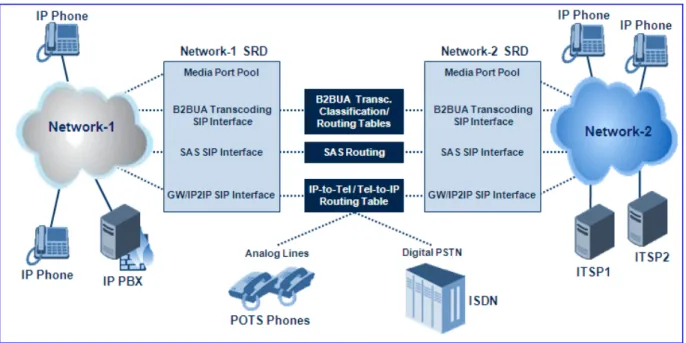
The figure below illustrates two SRD's - one for Netwrok-1 and one for Network-2. Each of the applications (i.e., SAS, Gateway\IP2IP, and B2BUA Transcoding) pertain to the same SRD, but each having its own SIP interface.
Mediant 2000 & Mediant 3000
Figure 1-1: Example Showing SIP Interfaces per Application Within SRD
1.3.1.2 SIP Interfaces
The device now supports the configuration of multiple SIP signaling interfaces, using the SIP Interface table. A SIP Interface represents one SIP signaling entity, which is a combination of UDP, TCP, and TLS ports relating to one specific IP address (network interface, configured in the Multiple Interface table). The SIP Interface is configured with a corresponding SRD. This allows User Agents on the network to communicate with a specific SRD, using the SIP Interface (signaling interface) associated with it.
Each SRD may be associated with up to three SIP Interfaces (one per application type - SAS, Gateway\IP-to-IP, and B2BUA Transcoding). Each SIP Interface must have a unique signaling port (i.e., no two SIP Interfaces can share the same port - no overlapping).
SIP Interfaces are used for the following:
Defining different SIP signaling ports (listening UDP, TCP, and TLS, and the UDP source ports) for a single or multiple interfaces.
Differentiating between the different applications supported by the device (i.e., SAS, Gateway\IP2IP, and B2BUA Transcoding). Only one signaling interfaces (IPv4) per application type is allowed per SRD.
Separating signaling traffic of different customers to use different routing tables, manipulations, SIP definitions, etc..
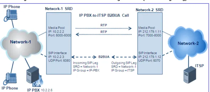
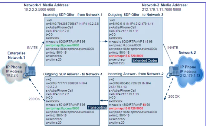
Network-2 Media: 212.179.1.11:7000-8000
Figure 1-2: Back-to-Back B2BUA Transcoding Call Flow (RTP and Signaling)
1.3.1.3 Media Realm
A pool of media interfaces called Media Realms can be defined in the SIP Media Realm table. A Media Realm is range of UDP ports, which are associated with a media IP interface (defined in the Multiple Interface table). Therefore, Media Realms allow the user to divide a media-type IP interface into several realms, where each realm is specified by a UDP port range. Once created, the Media Realm can be assigned to an IP Group ID (in the 'IP Group' table), and/or SRD (in the 'SRD' table).
Mediant 2000 & Mediant 3000
1.3.2
SIP Dialog Initiation Process
The device’s SIP dialog initiation process concerns all incoming SIP dialog initiation requests. This includes the SIP methods such as INVITE, SUBSCRIBE, OPTIONS, REFER, INFO, UNSOLICITED NOTIFY, MESSAGE, and REGISTER.
The SIP dialog initiation process consists of the following stages:
Determining Source and Destination URL (refer to Section 1.3.2.1 on page 33)
Source IP Group Classification (refer to Section 1.3.2.2 on page 33)
IP-to-IP Routing (refer to Section 1.3.2.3 on page 35)
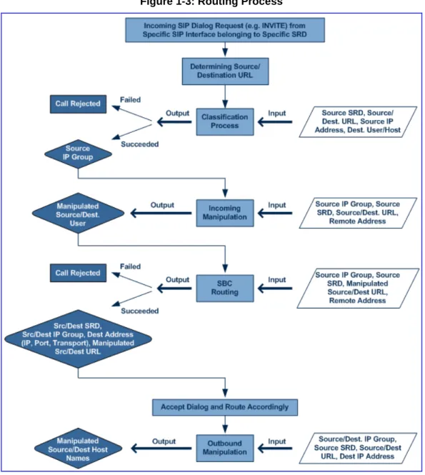
IP-to-IP Inbound and Outbound Manipulation (refer to Section 1.3.2.4 on page 36) The flowchart below illustrates this process:
1.3.2.1 Determining Source and Destination URL
The SIP protocol has more than one URL in a dialog establishing request that might represent the source and destination URL. When handling an incoming request, the device determines which SIP headers are used for source and destination URL’s. Once these URL’s are determined, the input user and host are taken from these URLs.
INVITE dialogs:
• Source URL: if exists, obtained from the P-Asserted\Preferred-Identity header; Otherwise, from the From header
• Destination URL: obtained from the Request URI
REGISTER dialogs:
• Source URL: obtained from the To header • Destination URL: obtained from the Request URI
1.3.2.2 Source IP Group Classification
The device now supports the configuration of rules for classifying incoming SIP dialog initiating request. The classification identifies the incoming SIP dialog request as belonging to a specific IP Group (from where the SIP dialog request originated).
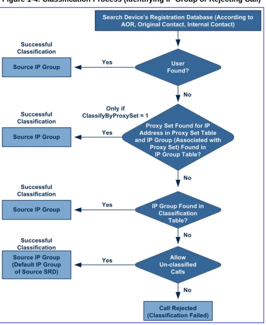
Classification begins in the device's Registration database, where it searches for a match by checking if the request arrived from a registered user:
Compares received Contact to the Contact of the registered user
Compares P-Asserted/From URL to the registered AOR
If the database search is unsuccessful, the classification process proceeds with locating a Proxy Set (associated with the SIP dialog request’s IP address) and then finding a match with a corresponding IP Group in the IP Group table. Each IP Group can be classified according to its Proxy Set (if in the IP Group table the parameter ClassifyByProxySet is enabled). If enabled, the device classifies Requests arriving from the IP Group’s Proxy Set as coming from this IP Group. The classification is done according to the Proxy IP list (in case of host names, then according to the dynamically resolved IP address list). Note that this classification is not relevant in cases where multiple IP Groups use the same Proxy Set.
If classification based on Proxy Set is unsuccessful, the device proceeds to the Classification table, which searches for a source IP Group based on the following matching rules: Source IP Address, Source Username Prefix, Source Host Prefix, Destination Username Prefix, Destination Host Prefix, and Source SRD.
If the above classification process fails to determine the source IP Group to which the incoming packet belongs, the call can either be rejected, or allowed and processed (by assigning it to the default IP Group of the default SRD). This last classification is determined by the parameter AllowUnclassifiedCalls.
Mediant 2000 & Mediant 3000
This IP Group is afterwards used for the following purposes:
Input for the manipulation and routing processes
Defining SIP behavior and IP Profile, Media realm and matching account
Note: Incoming REGISTER messages are recorded in the device’s database sent to a destination only if they are associated with a source IP Group that is of USER type.
The flowchart below illustrates the classification process:
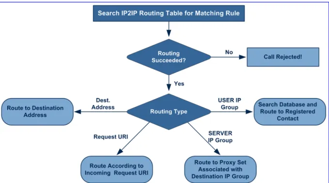
1.3.2.3 IP-to-IP Routing
The device's B2BUA Transcoding application employs a comprehensive and flexible routing scheme:
Routing rules according to Layer 3/4 and SIP characteristics
Routing to multiple destination types:
• Request-URI (of incoming SIP dialog initiating requests) • Specific destination IP address
• Specific FQDN (NAPTR/SRV/A-Record Resolutions)
• Registered Contact in device's database (User-type IP Groups)
• IP Group (address defined for Proxy Set associated with the IP Group), with the ability of load balancing and redundancy
Alternative Routing
Routing between two different Layer-3 networks
Transport protocol translator (UDP to TCP to TLS)
Source and destination user name manipulation (pre/post routing)
The device now provides a new IP-to-IP Routing table (IP2IPRouting) for configuring the IP-to-IP routing rules. This table provides enhanced IP-IP-to-IP call routing capabilities for routing received SIP messages such as INVITE messages to a destination IP address. The routing rule must match one of the following input characteristics: Source IP Group, Source Phone Prefix, and/or Source Host Prefix.
Note: SIP REGISTER messages are routed only by using Destination IP Groups defined in the IP-to-IP routing rules.
The IP2IP Routing table determines the destination route according to any one of the following:
Registered User Contact listed in the device's database (only for USER IP Groups)
Destination IP Group's associated Proxy Set (allows redundancy/load balancing)
Specific destination address (can be based on IP address, Host name, port, transport type, and/or SRD). Routing to a host name can be resolved using NAPTR/SRV/A-Record.
Incoming Request URI
For all destination types listed above except destination IP Group, the IP Group can optionally be itself, configured to provide destination SRD and/or IP Profile. If neither destination SRD nor destination IP Group are defined, the destination SRD is the source SRD and the destination IP Group is its default IP Group.
Mediant 2000 & Mediant 3000
Figure 1-5: IP-to-IP Routing Types
In addition to the alternative routing/load balancing provided by the Destination's IP Group's associated Proxy Set, the IP2IP Routing table also allows the configuration of alternative routes, whereby if a route fails, the next adjacent rule in the table that is configured as 'Alt Route Ignore/Consider Inputs' are used. The alternative routes rules can be set to enforce the input matching criteria or to ignore any matching criteria. For alternative routing, alternative routing reasons (i.e., 4xx, 5xx, and 6xx SIP responses) must be configured in the ‘Alternative Routing Reasons’ table (SBCAlternativeRoutingReasons)
If no matching rule is located in the table, the call is rejected.
.
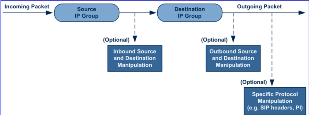
1.3.2.4 IP-to-IP Inbound and Outbound Manipulation
The device now supports SIP URI user part (source and destination) manipulations, whereby a manipulation rule in the table is located according to the source IP group, and source and destination host and user prefixes. Since outbound manipulations are performed after routing, the outbound manipulation rule matching can also be done by destination IP Group. The manipulation rules apply to INVITE, OPTIONS, and SUBSCRIBE messages (not REGISTER messages).
Host name (source and destination) manipulations are simply host name substitutions with the names defined for the source and destination IP Groups respectively (if any, in the IP Group table).
Manipulated destination user and host are performed to the following SIP headers: Request URI, To, and Remote party ID (if exists). Manipulated source user and host are performed to the following SIP headers: From, P-Asserted (if exists), P-Preferred (if exists), and Remote party ID (if exists).
Figure 1-6: IP-to-IP Routing Process
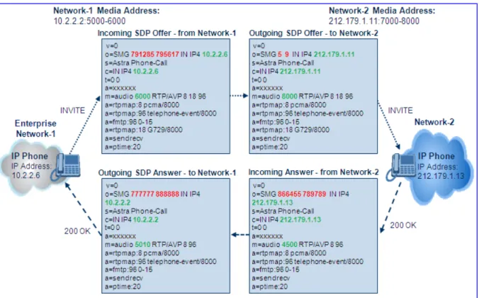
Below is an example of a call flow and consequent SIP URI manipulations: Figure 1-7: SIP INVITE (Manipulations) between Different Networks
The B2BUA Transcoding application above performs the following SIP message manipulations (contributing to typical topology hiding):
SIP Manipulation From Inbound Source SIP URI User Name
To
7000 97000 (blue)
Source IP Group Name (SIP URI Host Name) 10.2.2.6 IP_PBX (blue)
Inbound Destination SIP URI User Name 1000 9721000 (red)
Destination IP Group Name (SIP URI Host Name)
10.2.2.3 ITSP (red)