BII 42092 Publications No. Issue Date
INSTALLATION
INSTRUCTIONS
Accessory Application REMOTE CONTROL ENGINE STARTER 2010 MDX JAN 2010 PARTS LISTRemote Engine Starter Unit Kit P/N 08E91-E22-200B Transmitter Control unit Antenna Key ring Protective tape Fuse label Caution label
Accessory User’s Information Manual
Quick Start Guide
Remote Control Engine Starter Attachment Kit P/N 08E92-STX-200B
Engine starter harness
Engine starter subharness
Engine starter control unit bracket
Template
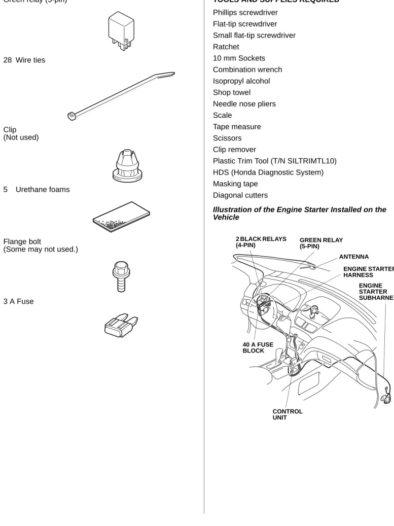
Green relay (5-pin) 28 Wire ties Clip (Not used) 5 Urethane foams Flange bolt
(Some may not used.)
3 A Fuse
TOOLS AND SUPPLIES REQUIRED Phillips screwdriver
Flat-tip screwdriver Small flat-tip screwdriver Ratchet
10 mm Sockets Combination wrench Isopropyl alcohol Shop towel Needle nose pliers Scale
Tape measure Scissors Clip remover
Plastic Trim Tool (T/N SILTRIMTL10) HDS (Honda Diagnostic System) Masking tape
Diagonal cutters
Illustration of the Engine Starter Installed on the Vehicle 920557AH GREEN RELAY (5-PIN) ANTENNA ENGINE STARTER HARNESS CONTROL UNIT 40 A FUSE BLOCK 2 BLACK RELAYS (4-PIN) ENGINE STARTER SUBHARNESS
INSTALLATION
NOTE: This antenna should be installed only if the ambient air temperature is 15°C (60°F) or above.
1. Make sure you have the anti-theft code for the radio. 2. Disconnect the negative cable from the battery.
Client Information: The information in this installation instruction is intended for use only by skilled
technicians who have the proper tools, equipment, and training to correctly and safely add equipment to your vehicle. These procedures should not be attempted by “do-it-yourselfers.”
Setting the Control Unit
3. Using a small flat-tip screwdriver, adjust the switches on the (accessory) control unit to the locations shown.
NOTE:
• The switches must be set before the control unit is plugged in.
• If the switch settings are not correct, the remote engine starter will not operate correctly.
• If you are setting the switches with the control unit installed in the vehicle, touch the metal part of the screwdriver to any metal part of the vehicle to discharge any static electricity.
• If you change the switch settings with the unit connected, you must disconnect the unit, then reconnect it before the unit recognizes the new settings. CONTROL UNIT Discharge any static electricity. SET SWITCHES SWITCHES SW:1 RR Junction unit --- > ON SW:2 Trunk or Tailgate --- > ON SW:3 Smart Entry --- > OFF SW:4 Horn or Buzzer Answerback ---- > OFF SW:5 Trunk Main SW --- > OFF SW:6 Reserve--- > ON SMALL
FLAT-TIP SCREW-DRIVER
The switches must be set before the control unit is plugged in.
4. Using isopropyl alcohol on a shop towel, clean the control unit where the protective tape will attach. Remove the adhesive backing, and attach the protective tape to the control unit over the switch opening.
Removing the Vehicle Parts
5. Open the pocket, and remove two screws.
772505AS CONTROL UNIT SWITCH OPENING PROTECTIVE TAPE ADHESIVE BACKING Clean with isopropyl alcohol. 920401AH POCKET 2 SCREWS
6. Using a plastic trim tool, remove the roof console (two clips and unplug three vehicle connectors).
7. Remove the sunvisor holders. Using a flat-tip screwdriver, push the hook, and turn the holder 90°, then pull it out.
920402AH
PLASTIC TRIM TOOL
3 VEHICLE CONNECTORS ROOF CONSOLE 2 CLIPS 920501AH FLAT-TIP SCREWDRIVER 2 SUNVISOR HOLDERS Turn.
8. Using a plastic trim tool and a shop towel, remove the cap (four tabs).
9. Pull away the weatherstrip. Remove the bolt and the washer.
10. Remove the left front A-pillar trim (two clips).
942202AH
PLASTIC TRIM TOOL
CAP WASHER BOLT WEATHERSTRIP 4 TABS 920404AH 2 CLIPS LEFT FRONT A-PILLAR TRIM
11. Turn the knob counterclockwise, then pull out the driver’s dashboard under cover (one clip and two pins). Release the vehicle harness clip and unplug the two vehicle connectors to remove the driver’s dashboard under cover.
12. Pull away the weatherstrip, and then remove the driver’s dashboard side cover (six retaining tabs).
920502AH
PIN VEHICLE HARNESS CLIP
PIN KNOB CLIP DRIVER’S DASHBOARD UNDER COVER 2 VEHICLE CONNECTORS
2 RETAINING TABS WEATHERSTRIP
4 RETAINING TABS
13. Remove the left front door sill trim (four clips, two retaining tabs and two pins).
14. Pull away the weatherstrip, and remove the left kick panel (two clips).
920422AJ
LEFT FRONT DOOR SILL TRIM
2 RETAINING TABS PIN 4 CLIPS PIN 920423AJ WEATHERSTRIP CLIP CLIP LEFT KICK PANEL
15. Using a plastic trim tool and a shop towel, remove the driver’s outer dashboard trim (four clips and vehicle connectors).
16. Using a plastic trim tool and a shop towel, remove the driver’s center trim (five clips and three retaining tabs). 920504BH DRIVER’S OUTER DASHBOARD TRIM PLASTIC TRIM TOOL 4 CLIPS VEHICLE CONNECTORS 920424BJ 5 CLIPS 3 RETAINING TABS DRIVER’S CENTER TRIM PLASTIC TRIM TOOL
17. Remove the driver’s lower dashboard cover (one self-tapping screw and nine clips). If equipped, unplug the A/C sensor (two retaining tabs).
18. Release the driver’s center console trim (eight clips) as shown below. 920505AH A/C SENSOR 2 RETAINING TABS A/C SENSOR SELF-TAPPING SCREW 9 CLIPS DRIVER’S LOWER DASHBOARD COVER 920506AH 2 CLIPS 6 CLIPS DRIVER’S CENTER CONSOLE TRIM
19. Remove the passenger’s dashboard under cover (five clips, and release two pins and two vehicle connectors).
20. Remove the right front door sill trim (four clips, two retaining tabs and two pins).
920508AH 2 VEHICLE CONNECTORS 2 PINS PASSENGER’S DASHBOARD UNDER COVER 5 CLIPS 920507AH 4 CLIPS RIGHT FRONT DOOR SILL TRIM
2 RETAINING TABS
FRONT PIN
21. Pull away the weatherstrip, and remove the right kick panel (two clips).
920509AH WEATHERSTRIP RIGHT KICK PANEL CLIP CLIP
Installing the Antenna
22. Wrap three pieces of urethane foam around the antenna cable at the measurements shown.
23. Using scissors, cut one urethane foam piece in half. Wrap the two halves of the urethane foam around the antenna cable at the measurements shown.
920510AH 380 mm (15 in.) 30 mm (1.2 in.) URETHANE FOAM ANTENNA CABLE 735 mm (29 in.) URETHANE FOAM Cut. ANTENNA
24. Measure and mark the antenna plate, using two pairs of needle nose pliers, bend the antenna plate to the angle shown.
920511AH ANTENNA 7 mm (0.25 in.) 15 mm (0.6 in.) ANTENNA PLATE SCALE NEEDLE NOSE PLIERS ANTENNA PLATE
25. Using scissors, cut out the template.
26. Secure the template to the windshield with the masking tape by aligning it with the edge of the black ceramic part as shown.
920512AH TEMPLATE Cut out. 920513AH BLACK CERAMIC PART MASKING TAPE TEMPLATE REARVIEW MIRROR WINDSHIELD
27. Using isopropyl alcohol on a shop towel, clean the area where the antenna will attach.
28. Remove the adhesive backing from the antenna. Insert the antenna plate behind the roof lining, and attach the antenna to the windshield aligning with the template. Apply pressure to the antenna base to make sure it sticks to the windshield.
29. Remove the template.
920514AH
ROOF LINING Clean with isopropyl alcohol. TEMPLATE ADHESIVE BACKING ANTENNA ANTENNA PLATE
30. Gently pull down the roof lining, and tuck the antenna cable under it. Be careful not to crease the roof lining.
31. Route the antenna cable down along the left front A-pillar and the vehicle harness.
32. Pull away the weatherstrip. Route the antenna cable down under the dashboard. Tuck the antenna cable between the left front A-pillar and the dashboard, and reinstall the weatherstrip.
920515AH ROOF LINING LEFT FRONT A-PILLAR VEHICLE HARNESS ANTENNA CABLE 920516AH WEATHERSTRIP DASHBOARD ANTENNA CABLE LEFT FRONT A-PILLAR
33. Using isopropyl alcohol on a shop towel, clean the roof panel where the urethane foam will attach.
34. Secure the antenna cable to the vehicle harness with one wire tie.
35. Secure the antenna cable to the roof panel with one urethane foam in the area shown.
36. Along the left front A-pillar, secure the antenna cable to the vehicle harness with four wire ties.
920517AH VEHICLE HARNESS ANTENNA CABLE WIRE TIE URETHANE FOAM Clean with isopropyl alcohol. 920518AH LEFT FRONT A-PILLAR VEHICLE HARNESS ANTENNA CABLE 4 WIRE TIES
37. At the dashboard area, secure the antenna cable to the vehicle harness with one wire tie.
Routing the Engine Starter Harness
38. Install the three relays to the engine starter harness relay blocks. Be careful to install the relays properly to avoid a malfunction.
39. Using isopropyl alcohol on a shop towel, clean the fuse block where the fuse label will attach. Attach the 40A ENG STARTER fuse label to the engine starter harness fuse block.
920519AH VEHICLE HARNESS ANTENNA CABLE WIRE TIE 920520AH 2 BLACK RELAYS (4-PIN) GREEN RELAY (5-PIN) 40A ENG STARTER FUSE LABEL RELAY BLOCK ENGINE STARTER HARNESS FUSE BLOCK
40. At the fuse box, locate and unlock the two vehicle connectors, then unplug them from the fuse box.
41. Unplug the vehicle 6-pin connector (green) from the fuse box.
920521BH
FUSE BOX
UNLOCK 2 VEHICLE CONNECTOR
VEHICLE 6-PIN CONNECTOR (GREEN)
42. Secure the clip on the engine starter harness to the fuse box as shown.
920522CH
CLIP
FUSE BOX
FRONT
43. Plug the engine starter harness 6-pin connector (green) into the fuse box, and plug the vehicle 6-pin connector (green) into the engine starter harness 6-pin connector (green).
NOTE: Make sure the engine starter harness and vehicle 6-pin connectors (green) are plugged in securely. A loose connector can cause the engine to stall.
44. Plug the engine starter harness 6-pin connector (blue) into the fuse box.
45. Reconnect the two vehicle connectors unplugged in step 40.
46. Attach the engine starter harness relay block to the vehicle relay block as shown.
920523BH
FUSE BOX
Pull the connector to make sure it is securely locked. VEHICLE 6-PIN CONNECTOR (GREEN) 2 ENGINE STARTER HARNESS 6-PIN CONNECTORS (GREEN) ENGINE STARTER HARNESS 6-PIN CONNECTOR (BLUE)
47. Remove the vehicle control unit (one bolt), and let the control unit hang.
48. Route the two engine starter harness 14-pin connectors over the steering shaft.
920524AH VEHICLE RELAY BLOCK ENGINE STARTER HARNESS RELAY BLOCK 920525AH BOLT VEHICLE CONTROL UNIT STEERING SHAFT
49. Directly behind the steering shaft, unplug the vehicle 22-pin connector and 6-pin connector for access, and the vehicle 14-pin connector (white).
50. Plug the engine starter harness 14-pin connector into the vehicle 14-pin connector and plug the
920526CH ENGINE STARTER HARNESS STEERING SHAFT 2 ENGINE STARTER HARNESS 14-PIN CONNECTORS 920527AH VEHICLE 6-PIN CONNECTOR unplug for access.
VEHICLE 22-PIN CONNECTOR unplug for access.
VEHICLE 14-PIN CONNECTORS (WHITE)
vehicle 14-pin connector into the engine starter harness 14-pin connector.
51. Replug the vehicle 22-pin connector.
52. Attach the engine starter harness 14-pin connector to the vehicle 6-pin connector.
53. Reconnect the vehicle 6-pin connector.
54. Secure the engine starter harness to the vehicle harness with two wire ties in the areas shown.
920528AH
VEHICLE 14-PIN CONNECTORS (WHITE) ENGINE STARTER HARNESS 14-PIN CONNECTORS VEHICLE 22-PIN CONNECTOR 920529AH VEHICLE 6-PIN CONNECTOR VEHICLE 6-PIN CONNECTOR
ENGINE STARTER HARNESS 14-PIN CONNECTORS
55. Reinstall the vehicle control unit with the bolt removed in step 47. Be sure the engine starter harness is above the control unit.
56. Secure the engine starter harness to the vehicle harness with three additional wire ties.
57. Secure the engine starter harness 6-pin connector (green) to the vehicle harness with one wire tie. Near
920530AH
2 WIRE TIES VEHICLE HARNESS ENGINE STARTER HARNESS 920531AH 3 WIRE TIES VEHICLE HARNESS ENGINE STARTER HARNESS
the relays, secure the engine starter harness (white tape) to the vehicle harness with one wire tie.
58. Secure the engine starter harness and antenna cable to the vehicle harness with one wire tie.
960201BH RELAYS ENGINE STARTER HARNESS (white tape) WIRE TIE VEHICLE HARNESS WIRE TIE ENGINE STARTER HARNESS 6-PIN CONNECTOR (GREEN) 920533CH ENGINE STARTER HARNESS VEHICLE HARNESS WIRE TIE ANTENNA CABLE
59. Route the engine starter harness 12-pin connector and antenna cable along the dashboard frame towards the center console.
60. At the center console, route the engine starter harness 12-pin connector and antenna cable connector down along the vehicle harness to the driver’s center console trim opening.
920534AH
DASHBOARD FRAME
ANTENNA
CABLE ENGINE STARTER HARNESS 12-PIN CONNECTOR 920535AH DRIVER’S CENTER CONSOLE TRIM OPENING VEHICLE HARNESS ENGINE STARTER HARNESS 12-PIN
CONNECTOR ANTENNA CABLE CONNECTOR
61. Secure the engine starter harness and antenna cable to the dashboard frame with three wire ties.
62. Secure the engine starter harness and antenna cable to the vehicle harness with one wire tie.
920536AH DASHBOARD FRAME ENGINE STARTER HARNESS WIRE TIE ANTENNA CABLE 3 WIRE TIES 920537AH ENGINE STARTER HARNESS WIRE TIE ANTENNA CABLE VEHICLE HARNESS
Routing the Engine Starter Subharness
63. At the right kick panel (removed in step 21), slide the holder on the engine starter subharness 34-pin connector onto the holder lock on the vehicle 6-pin connector.
64. Unplug the vehicle 34-pin connector, and plug the engine starter subharness 34-pin connectors in between. 920538BH RIGHT FRONT LOWER PILLAR ENGINE STARTER SUBHARNESS 34-PIN CONNECTOR VEHICLE 34-PIN CONNECTOR VEHICLE 34-PIN CONNECTOR VEHICLE 6-PIN CONNECTOR
65. If equipped, remove the vehicle connector using the clip remover.
66. Remove the vehicle ground bolt. Attach the engine starter subharness ground terminal, and reinstall the vehicle ground bolt you just removed.
67. Secure the engine starter subharness to the vehicle harness with two wire ties.
941001AH VEHICLE CONNECTOR CLIP REMOVER 920539AH ENGINE STARTER SUBHARNESS GROUND TERMINAL 2 WIRE TIES VEHICLE HARNESS ENGINE STARTER SUBHARNESS VEHICLE GROUND BOLT (Reuse.)
68. Route the engine starter subharness under the blower motor, and along the vehicle harness towards the center console.
920540AH BLOWER MOTOR ENGINE STARTER SUBHARNESS VEHICLE HARNESS
69. Pull the end of the passenger’s center console trim to release the one clip shown. Route the engine starter subharness along the vehicle harness to the driver’s center console trim opening.
NOTE: Pull carefully on the passenger’s center console trim so you do not damage it.
920541AH FRONT CLIP TOP VIEW PASSENGER’S CENTER CONSOLE TRIM ENGINE STARTER
SUBHARNESS DRIVER’S CENTER CONSOLE TRIM OPENING VEHICLE
70. Secure the engine starter subharness to the vehicle harness with four wire ties in the areas shown.
71. Behind the center console, secure the engine starter subharness to the vehicle harness with one wire tie.
920542AH ENGINE STARTER SUBHARNESS VEHICLE HARNESS 4 WIRE TIES 920543AH ENGINE STARTER SUBHARNESS VEHICLE HARNESS WIRE TIE
Installing the Control Unit
72. Install the clip of the engine starter subharness to the engine starter control unit bracket as shown.
73. Install the engine starter control unit bracket and plug the engine starter subharness 28-pin connector into the control unit. Note the direction of the bracket.
920545AH CLIP ENGINE STARTER CONTROL UNIT BRACKET ENGINE STARTER SUBHARNESS 920546AH CONTROL UNIT ENGINE STARTER CONTROL UNIT BRACKET ENGINE STARTER SUBHARNESS 28-PIN CONNECTOR
74. Connect the antenna lead to the control unit as shown.
75. Plug the engine starter subharness 12-pin connector into the engine starter harness 12-pin connector.
920547AH CONTROL UNIT FRONT ANTENNA LEAD 920548AH ENGINE STARTER SUBHARNESS 12-PIN CONNECTOR ENGINE STARTER HARNESS 12-PIN CONNECTOR CONTROL UNIT FRONT
76. Install the engine starter control unit bracket to the vehicle bracket using a flange bolt.
NOTE: If the AC inverter unit is mounted on the vehicle bracket, install the engine starter unit and bracket to the vehicle bracket by reusing the AC inverter unit mounting bolt.
Without AC inverter unit
With AC inverter unit
920549AH VEHICLE BRACKET FLANGE BOLT ENGINE STARTER CONTROL UNIT BRACKET 920550AH AC INVERTER UNIT ENGINE STARTER CONTROL UNIT BRACKET
VEHICLE BOLT (Reuse.) fastening the AC inverter unit.
77. Install the clip on the engine starter subharness 12-pin connector to the engine starter control unit bracket as shown.
78. Secure the engine starter harness, engine starter subharness, and antenna cable to the vehicle harness with two wire ties as shown. Bundle the excess antenna cable and secure it using one wire tie as shown. 920551AH ENGINE STARTER CONTROL UNIT BRACKET ENGINE STARTER SUBHARNESS 12-PIN CONNECTOR CLIP 920552AH ENGINE STARTER HARNESS Bundle the excess antenna cable. ANTENNA CABLE VEHICLE HARNESS ENGINE STARTER SUBHARNESS 3 WIRE TIES
79. Remove the fuse box lid from left kick panel.
80. Install the 3A fuse included in the kit into the No. 33 slot of the fuse box.
920553BH FUSE BOX LID LEFT KICK PANEL 920554BH No. 33 3A FUSE FUSE BOX
81. Using isopropyl alcohol on a shop towel, clean the area where the fuse label will attach. Attach the 3 A ENG STARTER fuse label to the No.33 slot on the inside of the fuse box lid.
82. Using isopropyl alcohol on a shop towel, clean the area where the caution label will attach. Attach the caution label to the under side of the hood as shown.
920555AH
No. 33 3 A ENG STARTER
FUSE LABEL
FUSE BOX LID
Clean with isopropyl alcohol. 920556AH ADHESIVE BACKING Clean with isopropyl alcohol. HOOD CAUTION LABEL
83. Check that all wire harnesses and cables are routed properly and that all connectors are plugged in. 84. Reinstall all removed parts. Check that all clips and
other fasteners are installed securely.
85. Reconnect the negative cable to the battery. Check that the electrical accessory and other electrical systems function properly.
86. Enter the client’s radio anti-theft code. 87. Reset the clock.
88. Perform “REMOTE ENGINE STARTER REGISTRATION” and “FUNCTION CHECK”.
REMOTE ENGINE STARTER REGISTRATION 1. Get the PCM Code from ISIS.
2. Connect the HDS tester to the OBD II data link connector, then turn the ignition switch on. 3. Start the HDS, and click the car icon.
4. Input the VIN and other needed information, then click the check button.
792901AH
CAR ICON
752502AS
CHECK BUTTON Input the VIN and
other information.
5. Select “Honda Systems”, then click the check button.
6. Select “R/C ENG STARTER” and click the check button.
752503AS
Select the
“Honda Systems.” CHECK BUTTON
752504AS
Select the
7. Check that “REMARKS” is shown, then click the check button.
8. Select “REGISTER REMOTE CONTROL ENGINE STARTER UNIT”, then click the check button.
752505AS
Check that “REMARKS” is shown.
CHECK BUTTON
752506AS
Select the
“REGISTER REMOTE CONTROL ENGINE STARTER UNIT.”
CHECK BUTTON
9. Check that “Obtain PCM-code (IMMOBILIZER PCM CODE) from iN. This vehicle’s VIN will be required to obtain the password. (USA)” is shown, then click the check button.
10. Input the PCM Code, then click the check button. NOTE: To ensure security, the PCM code
(password) is changed every day, so it is impossible to register the remote controlled engine starter if the date of the PCM code acquisition and registration are different. The date of the HDS tester should also be the same.
752507AS
Check that “Obtain PCM-code (IMMOBILIZER PCM CODE) from iN. This vehicle’s VIN will be required to obtain the password. (USA)” is shown.
CHECK BUTTON
752509AS
Input the PCM Code.
11. Check that “The registration of the Remote Control Engine Starter Unit has been completed” is shown, then click the check button.
12. Check that “Check that the engine can be started by the Transmitter” is shown, then click the check button.
13. Perform the function test on the next page, then remove the HDS.
752510AS
Check that “The registration of the Remote Control Engine Starter Unit has been completed” is shown.
CHECK BUTTON
752511AS
Check that “Check that the engine can be started by the Transmitter” is shown.
732904AY DISPLAY STOP BUTTON COMMAND BUTTON START BUTTON TRANSMITTER FUNCTION CHECK Operating Conditions • Hood is closed • Shift lever in park
• The key is outside of the vehicle
• All doors and tailgate are closed and locked Inspection
1. Press the command button, and then, within 1 second, press the start button on the transmitter. The engine should start if all operating conditions are met.
Does the engine start?
2. Press the command button on the transmitter, and within 1 second, press the stop button. The engine should stop. Does the engine stop?
Yes - Operation is normal. No:
• Make sure all “Operating Conditions” are met. • Check the engine starter harness connections. • Connect the HDS and check for an indicated failure.
(Refer to the appropriate service manual for details.)
Yes - Operation is normal.
No - Check the engine starter harness connections.
3. After the engine has stopped, start the engine again, and check that the engine stops after each of the following conditions:
NOTE: After each test the driver’s door must be opened and closed.
• Move the shift lever out of the P position. • Unlock or open the doors or the tailgate. • Open the hood.
• Insert the key in the ignition switch. • Press the brake pedal.
Does the engine stop after each of these tests?
4. When the engine is started with the transmitter, make sure the power windows and the moonroof do not function, and Yes - Operation is normal.
No - Check the engine starter harness connections.
that the shift lever cannot be moved out of the P position.
5. Press the command button on the transmitter two times, and check the vehicle condition on the display. 6. Check the operation of the transmitter when the vehicle is 61 m (200 ft.) away and in direct sight.