Proceedings of the
12th International Workshop on Graph Transformation
and Visual Modeling Techniques
(GTVMT 2013)
The ScenarioTools Play-Out of Modal Sequence Diagram Specifications
with Environment Assumptions
Christian Brenner, Joel Greenyer and Valerio Panzica La Manna
14 pages
Guest Editors: Matthias Tichy, Leila Ribeiro
Managing Editors: Tiziana Margaria, Julia Padberg, Gabriele Taentzer
The ScenarioTools Play-Out of Modal Sequence Diagram
Specifications with Environment Assumptions
Christian Brenner1, Joel Greenyer2and Valerio Panzica La Manna3
Software Engineering Group, Heinz Nixdorf Institute,
University of Paderborn, Zukunftsmeile 1, 33102 Paderborn, Germany.
Software Engineering Group,
Leibniz Universität Hannover, Welfengarten 1, 30167 Hannover, Germany.
Dependable Evolvable Pervasive Software Engineering (DEEPSE) Group, Dipartimento di Elettronica, Informazione e Bioingegneria, Politecnico di Milano,
Piazza Leonardo Da Vinci, 32, 20133 Milano, Italy
Abstract: Many software-intensive systems consist of multiple components that provide complex functionality by their interaction. The scenario-based languages LSCs and MSDs are intuitive, but precise means to specify interactions; the engi-neers can specify how a system can, must, or must not react to events in its envi-ronment. A key benefit of LSCs/MSDs is that they can be executed via the play-out algorithm, which allows engineers to perform an early automated analysis of the specification. However, LSCs/MSDs lack support for expressing also what can or cannot happen in the environment. This is crucial especially in embedded sys-tems: very often, the software will only be able to satisfy its requirements if certain assumptions are made about the behavior of mechanical parts or the physical en-vironment. We extend MSD specifications to formally express such environment assumptions, and propose a corresponding extension of the play-out algorithm. The concepts are implemented in a novel, Eclipse-based tool.
Keywords:scenario-based specification, visual modeling, reactive systems, embed-ded systems, simulation algorithm
1
Introduction
Modern embedded systems in areas like transportation, traffic, or production typically consist of multiple components that interact to provide complex functionality in diverse and some-times safety-critical situations. The scenario-based languages Live Sequence Charts (LSCs)
[DH01, HM03] and a recent variant, Modal Sequence Diagrams (MSDs) [HM08], give
One key benefit of using LSCs/MSDs is that the specification can be executed via theplay-out
algorithm [HM02]. This supports engineers in the early validation of a specification: by simu-lation, the engineers can check for contradictions among the scenarios and whether the behavior that emerges from the interplay of multiple scenarios reflects the stakeholders’ intentions.
The original definition of LSCs and MSDs, however, does not include any means to also de-scribe what can or cannot happen in the environment. But especially in embedded systems, where software controls physical processes, it is crucial to also consider that, due to the mechan-ical principles and the laws of physics, events in the environment cannot occur in arbitrary ways. In fact, often a software cannot satisfy its requirements unless certain assumptions about its environment are made. For a meaningful simulation, such constraints must also be considered.
As an example, we consider the simplified specification of the RailCab system1, which is
de-veloped at the University of Paderborn. Here, small, autonomous rail vehicles, calledRailCabs,
transport passengers and goods on demand. They travel ontrack sections, each controlled by a
track section control. Imagine the case of a RailCab approaching a crossing, which is a special kind of track section. Thecrossing controlis responsible for closing the barriers before a Rail-Cab is allowed to enter the crossing. The requirements, simplified, are as follows: When the RailCab approaches the end of its current track section, it must send a request to the crossing control for the permission to enter. The crossing control must then order the barriers to close and, if this was successful, should allow the RailCab to enter the crossing. The barriers can also be blocked; then the RailCab must not be allowed to enter. The reply, however, must be sent before the RailCab is no longer able to brake before the crossing, in case that there is a problem. In this example, we need to assume that the barriers, once ordered to be closed, will eventually be closed or blocked. Also, we assume that the barriers close or block before the RailCab reaches the point beyond which it is no longer able to brake before entering the crossing. If these assump-tions are not modeled explicitly, we have to assume that environment events occur in arbitrary order, which could easily violate the requirements and leads to meaningless simulations.
The contribution of this paper is threefold. First, we present an extension of MSDs to specify not only system requirements, but also environment assumptions. These assumptions can be
specified byassumption MSDs, which allow the engineer to flexibly describe what can or cannot
happen in the environment of a system, or how the environment of a system in turn reacts to events in the system. Second, we describe a novel extension to the play-out algorithm, which considers the environment assumptions. Third, we present a new, model-based tool suite, called
SCENARIOTOOLS, which integrates the extended play-out in the Eclipse Debug-Framework.
Our paper is structured as follows. After explaining the foundations in Sect.2, we introduce
our extension to model environment assumptions in MSD specifications in Sect.3. Section 4
presents the extended play-out algorithm and Sect. 5 reports on the tool implementation. We
discuss related work in Sect.6and conclude in Sect.7.
2
Foundations
MSDs were proposed by Harel and Maoz as a formal interpretation of UML sequence diagrams, based on the concepts of LSCs [HM08]. MSDs also generalize some concept of LSCs (see
[HM08] for details). In the following, we explain the basics of MSDs and the play-out algorithm.
2.1 MSD Specifications
An MSD specification consists of a set of MSDs. An MSD can be existential or universal
[HM03]. We focus on universal MSDs in this paper, by which engineers can specify temporal properties for all sequences of events that occur in the system. Each lifeline in an MSD represents an object in anobject system; an object can be anenvironment objector asystem object. The set of system objects is called thesystem; the set of environment objects is called theenvironment.
The objects can interchange messages. A message has a sending and receiving object and
refers to an operation which must be defined for the receiving object. Thenameof the operation
is also that of the message. Here we consider onlysynchronousmessages where both sending
and receiving is a single event. We call the sending and receiving of a message amessage event
or simplyevent.
A message in an MSD, also called adiagram message, has a name and a sending and a
receiv-ing lifeline. The messages in an MSD have atemperatureand anexecution kind. The temperature
can be eitherhotorcold; the execution kind can be eithermonitoredorexecuted.
Intuitively, an MSD progresses as messages occur in the system as described in the MSD. If the progress reaches a message that is monitored, this message may or may not occur. If the message is executed, the message must eventually occur. If the message is hot, no message must occur that the scenario specifies to occur earlier or later. If the message is cold and a message occurs that is specified to occur earlier or later, this “aborts” the progress of the MSD. Messages that are not specified in the MSD are ignored.
More specifically, the semantics of the messages is as follows: An event can beunifiedwith
a message in an MSD iff the event name equals the message name and the sending and the receiving objects are represented by the sending resp. receiving lifelines of the message. When
an event occurs in the system that can be unified with the first message in an MSD, anactive
MSDis created. As further events occur that can be unified with the subsequent messages in
the diagram, the active MSD progresses. This progress is captured by thecut, which marks for
every lifeline the locations of the messages that were unified with the message events. If the cut reaches the end of an active MSD, the active MSD is terminated.
If the cut is in front of a message on its sending and receiving lifeline, the message isenabled. If a hot message is enabled, the cut is alsohot. Otherwise the cut iscold. If an executed message is enabled, the cut is alsoexecuted. Otherwise the cut ismonitored. An enabled executed message is called anactivemessage. Aviolationoccurs if a message event occurs that can be unified with a message in the MSD that is not currently enabled. If the cut is hot, it is a safety violation; if the cut is cold, it is called acold violation. Safety violations must never happen, while cold violations may occur and result in terminating the active MSD. If the cut is executed, this means that the active MSD must progress and it is aliveness violationif it does not. Instead, an active MSD is not required to progress in a monitored cut.
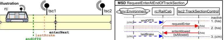
Figure1shows an MSD. We indicate the temperature and execution kind of diagram messages
by labels (e.g.(c/m)or(h/e)). Additionally, the red/blue color indicates the hot/cold temperature of a message; monitored messages have a dashed arrow, executed messages have a solid arrow.
reachable cuts, which are cold and monitored or hot and executed, labeled accordingly. Intu-itively, this MSD expresses the following requirements. We consider a scenario where a RailCab
moves along its current track section. At some point the RailCabrc detects that it reaches the
end of the current track section. This is modeled as the message endOfTSsent between the
environment and the RailCabrc. Now the RailCabrc must sendrequestEnterto the next
track section controltsc2, which must reply withenterAllowed. These two messages must
be sent before the RailCab reaches a point where it is possible for the last time to safely brake
before entering the switch (modeled by the environment messagelastBrake).
rc tsc2
illustration
endOfTSlastBrake
enterNext
tsc1 rc:RailCab tsc2:TrackSectionControl
MSD RequestEnterAtEndOfTrackSection
1. (h/e)
2. (h/e)
3. (c/m) inactive endOfTS
requestEnter
enterAllowed (isAllowed) lastBrake
env:Environment
(h/e)
(h/e) (c/m)
(c/m)
Figure 1: The MSDRequestEnterAtEndOfTrackSectionwith illustration
Messages are typically either cold and monitored or hot and executed, but they can for ex-ample also be hot and executed to express that something need not necessarily ever happen, but
until it does, something else is not allowed to happen. We will discuss an example in Sect.3.
Our message semantics differs slightly from the original definition of MSDs [HM08] where hot messages represent both the safety and the liveness aspects, i.e., it must eventually occur and must not be violated. Separating the two aspects makes the formalism more versatile.
Messages can also have parameters of certain types. Message events must then carry corre-sponding parameter values. In our approach, we only allow messages with at most one parameter.
This simplifies certain concepts explained in Sect.4and poses no fundamental restriction.
Mes-sages in the MSDs can either specify a concrete value for parameters, or they can besymbolic
and specify no concrete parameter value [HM03, pp. 91]; this is done by specifying as
param-eter value an unbound variable. Here the messageenterAllowedhas a Boolean parameter,
representing the choice to allow or deny the RailCab to enter. In this MSD, the message specifies
as parameter value the unbound variableisAllowed, thus the message is symbolic.
A message event and a diagram message that are unifiable are alsoparameter unifiableiff the
diagram message is symbolic or specifies the same parameter value as the message event. If a parametrized message is enabled, the cut progresses if the event is parameter unifiable with the enabled diagram message. In the case of a symbolic message, the unbound variable is then bound to the parameter value of the sent message. It is a violation (in addition to the previous notion of violation) if the event is unifiable, but not parameter unifiable with the an enabled diagram message.
2.2 Play-Out
Harel and Marelly defined an executable semantics for the LSCs, called the play-out
messages, then the algorithm non-deterministically (or by user interaction) chooses to send a corresponding message if that will not lead to a safety violation. The algorithm will repeat sending system messages until no active MSDs with active system messages remain. Then the algorithm will wait for the next environment event, and this process continues. (It is assumed that the system is always fast enough to send any finite number of messages before the next en-vironment event occurs.) If the play-out algorithm reaches a state where there are active system messages, but they all lead to safety violations, the algorithm terminates unsuccessfully. The
play-out algorithm is implemented in the PLAYENGINE[HM03] and the PLAYGOtool [Pla].
2.3 MSDs with Symbolic Lifelines
For systems like the RailCab, we can imagine many different instances, with different track layouts and different numbers of RailCabs. In addition, through the movement of RailCabs, the communication relationships among the objects can change.
When specifying the behavior of such dynamic systems, it is often impractical to consider
MSDs where each lifeline refers to a concrete object. Instead, symbolic lifelines were
intro-duced by Marelly et al. [MHK02,HM03], which refer to a class of objects; there can also be
inheritance relationships among classes [Mao09]. MSDs with symbolic lifelines are also called
symbolic MSD; MSDs with non-symbolic lifelines, also calledconcrete lifelines, are called con-crete MSDs. Here, concrete lifelines, in contrast to symbolic ones, have an underlined label.
In an active MSD with symbolic lifelines, a symbolic lifeline can bebound to an object that
is an instance of the class referenced by the lifeline. For a given object system, the semantics of a symbolic MSD is equivalent to a set of concrete MSDs where for each possible combination of bindings of the symbolic lifelines, there exists a corresponding concrete MSD. Typically, we want to restrict a symbolic MSD to specify the behavior only for objects with certain relation-ships or properties. Then,binding expressionsare added to restrict the possible lifeline bindings. Harel and Marelly extended the play-out algorithm to handle the dynamic binding of symbolic
lifelines, supporting a simple form of binding expressions [HM03, pp. 209]. In SCENARIO
-TOOLS, we implement similar mechanisms and consider binding expressions of the form
<life-line-name> := <expr>where<lifeline-name>is the name of a lifeline, also called
theslot lifeline, and<expr>is an OCL expression, also called thevalue expression. The value expression can evaluate to an object that is an instance of the slot lifeline’s class. Lifeline names can be used as variables within value expressions. If a lifeline is bound to an object, so is the corresponding variable. Also variables bound in the course of progressing symbolic diagram
messages (see Sect.2.1) can be used in the binding expressions. Value expressions can only be
evaluated when all the variables in the value expression are bound.
During play-out, symbolic MSDs and binding expressions are interpreted as follows: As a message event can be (parameter) unified with a first message in an MSD, an active MSD is created with the sending and receiving lifelines of the first message bound to the sending and receiving object of the message event. Then the value expressions of the binding expressions are evaluated as soon as possible, and the corresponding slot lifelines are bound to the resulting objects. It must not happen that a cut is before a message on its sending or receiving lifeline, but the receiving resp. sending lifeline is unbound.
shown on the right of Fig.2, executed in the context of an object system as illustrated on the left.
If the message endOfTSis sent from the environment objecte to the RailCab rc1, an active
MSD is created with the lifelineenvbound toeand the lifelinercbound torc1. Now the binding expression can be evaluated, which results in binding the lifelinenextto the objecttsc2.
endOfTS
rc:RailCab next:TrackSectionControl
requestEnter enterAllowed (isAllowed) MSD RequestEnterAtEndOfTrackSection
lastBrake
next := rc.current.next
tsc2:Track SectionControl next next tsc1:Track SectionControl rc1:RailCab ...next registered-RailCabs current ... (dynamic) object system
e:Environment endOfTS link message event env:Environment (c/m) (c/m) (h/e) (h/e)
Figure 2: A dynamic object system and the symbolic version of the MSD
RequestEnterAtEnd-OfTrackSection
We also consider that the value expression can evaluate to a set of objects. Then for each object in the set a copy of the active MSD is created with the slot lifeline bound to that object (as already defined by Harel and Marelly [HM03, pp. 215]).
3
Environment Assumptions and Other Extensions
While the concepts described above are already very powerful, they only allow us to specify constraints on the system behavior, but not over the possible environment behavior.
This is a limitation, as already motivated in the introduction by the example of a RailCab
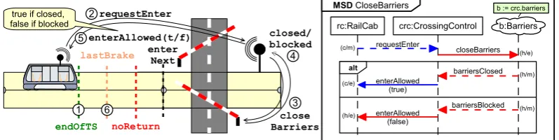
approaching a crossing. Let us consider this example in more detail. Figure3 illustrates the
example on the right. Upon notification that the RailCab approaches the end of its current track section (1), it must send a request to the crossing control for the permission to enter the crossing (2). The crossing control must then order the barriers to close (3) and, if this was successful (4), should allow the RailCab to enter the crossing (5). The barriers can also be blocked (4); then the RailCab must not be allowed to enter (5). The reply, however, must be sent before the RailCab reaches the point where it is no longer able to brake before the crossing (6).
enter Next requestEnter enterAllowed(t/f) close Barriers closed/ blocked 2 4 5 3 true if closed,
false if blocked rc:RailCab crc:CrossingControl
MSD CloseBarriers requestEnter enterAllowed (true) (h/e) (c/m) closeBarriers barriersClosed alt enterAllowed (false) barriersBlocked (h/m) (h/m) (c/e) (h/e)
b := crc.barriers
b:Barriers
endOfTS lastBrake
1 6
noReturn
Figure 3: The MSD defining the requirements for closing the barriers and an illustration
These requirements are captured formally by the MSD CloseBarriers shown on the right in
Fig.1and its interplay with the MSDRequestEnterAtEndOfTrackSection(Fig.2): Upon
RequestEnter-AtEndOfTrackSection requires the RailCab to sendrequestEnterto the next track section, which is in this case the crossing control. The crossing control class inherits from the track section control class; we omit the class diagram for brevity. In this case, where the recipient of
requestEnteris a crossing control, an active MSD ofCloseBarriersis created.
We suppose that the crossing control has a barriers object linked to it via the association
barriers, so the lifelineb:Barriers is bound immediately to this object. This object is an actua-tor/sensor component that closes the barriers and detects whether the barriers are closed, opened, or blocked. It is an environment object, because we, from the perspective of the software, can send commands to this component, but cannot control whether the barriers will be closed or blocked.
Next, the crossing control must send the message closeBarriers. Now there are two
alternatives, modeled by analternative fragment. An alternative fragment can span several life-lines and contains two or moresub-interactions, divided graphically by solid horizontal lines. If no conditions are specified, they model non-deterministic choices. If the first messages inside the sub-interactions are system messages, the choice can be made by the system; if the first messages are environment messages, the environment makes the choice, i.e., the system has to react dif-ferently to different things that can happen in the environment. In this case, the sub-interactions model that, when ordered to be closed, the barrier must either be closed or blocked, and then the crossing control should either allow or must deny the RailCab to enter the next track section.
(Note thatshould allow is modeled by a cold message, which may be violated if yet another
MSD would specify that for some other reason the RailCab must not be allowed to enter.)
Unfortunately, there are two problems with the above requirements. First, the MSDs
Request-EnterAtEndOfTrackSectionandCloseBarriers(Fig.1and2) can be easily violated as follows. In
a state where the crossing control sent the message closeBarriers, the system must wait
for the environment eventsbarriersClosed orbarriersBlockedto occur, before the
crossing control can send the replyenterAllowedto the RailCab. However, it is not
guar-anteed that the environment (the barriers, more specifically) will sendbarriersClosed or
barriersBlocked. The environment could, for example, send lastBrakeinstead. This
would lead to a safety violation in the MSDRequestEnterAtEndOfTrackSection. The
require-ments can only be satisfied if we can assume, for example, that the barriers will report to be
closed or blocked beforelastBrakeoccurs. Thus far, we are not able to express this formally.
Second, the play-out algorithm, even if we consider such an assumption, will not be able to execute the MSDs successfully. This is because, as described in Sect.2.2, the system must always immediately send active system messages without waiting for the environment. However, after
the crossing control sent the messagecloseBarriers, sending the active message
enter-AllowedbeforebarriersClosedorbarriersBlockedoccurred would lead to a safety
violation. Thus, the regular play-out algorithm is not suited to execute such specifications. To overcome these problems, we propose, first, a more flexible extension of the play-out algorithm that allows the system to wait for environment events also in the presence of active system messages. Second, we propose to explicitly model assumptions about the environment
behavior throughassumption MSDs.
The syntax and semantics of assumption MSDs is the same as for requirement MSDs, with only the following differences. Syntactically, assumption MSDs have an additional stereotype
not lead to a safety or liveness violation in any requirement MSD or if it leads to a safety or lifeness violation in at least one assumption MSD.
In practice, requirement MSDs are typically used to specify constraints over system messages, or how the system must react to environment events. Assumption MSDs are, by contrast, typ-ically used to specify constraints over environment events or how the environment will again react to system messages. Intuitively, we can then say that the system is only obliged to satisfy the requirement MSDs if the environment satisfies all assumption MSDs.
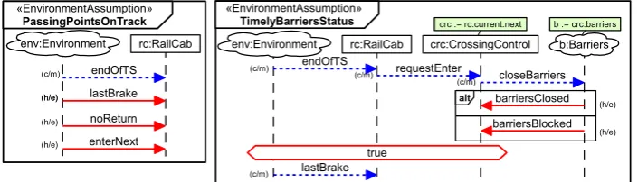
Figure4shows two assumption MSDs which explicitly formulate environment assumptions
that are necessary to make it possible for the system to satisfy the specification. Details on the play-out of MSD specifications with assumption MSDs are explained in the next section.
endOfTS rc:RailCab
lastBrake «EnvironmentAssumption»
PassingPointsOnTrack
enterNext noReturn
(c/m)
(h/e)
(h/e) (h/e)
«EnvironmentAssumption» TimelyBarriersStatus
rc:RailCab crc:CrossingControl
b := crc.barriers crc := rc.current.next
endOfTS requestEnter
closeBarriers
alt barriersClosed
barriersBlocked b:Barriers env:Environment
true lastBrake env:Environment
(c/m)
(h/e)
(c/m)
(c/m)
(c/m)
(h/e)
(h/e)
Figure 4: Assumption MSDs for the RailCab crossing example
Figure4shows on the left the assumption MSD PassingPointsOnTrack. It expresses the
as-sumption that the RailCab will pass the points on the track section as shown in Fig.3always in
the indicated order. (We assume, simplified, that the RailCab will not brake or reverse.)
On the right, Fig.4shows the MSDTimelyBarriersStatus. It specifies that the environment’s
reaction tocloseBarriers(i.e.,barriersClosed orbarriersBlocked) will occur
before the RailCab passes the point of the last safe brake.
With these environment assumptions, the system can satisfy its requirements. By considering these assumptions also in the play-out algorithm, the specification can be executed successfully. The extension of the play-out algorithm to also consider environment assumptions is explained in the next section.
4
Extended Play-out
The play-out algorithm of SCENARIOTOOLSdiffers from the play-out algorithm in the PLAY
ENGINEand the PLAYGOtool conceptually in two ways. First, it explicitly considers
environ-ment assumptions that can be specified as introduced above. Second, after each step, it collects for each message event information about its effect in the next step. This way, the user can for example see whether a message will progress cold or hot messages, or whether the message will lead to a cold or safety violation in an assumption or requirement MSD. This information is highly valuable for the user to understand the consequences of choosing particular steps.
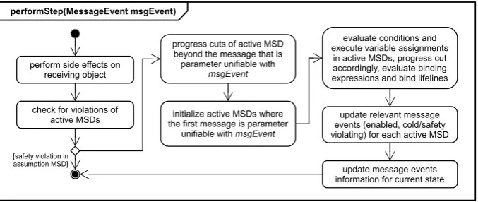
The SCENARIOTOOLSplay-out algorithm basically consists of repeated executions of
event is computed by calls of theperformStepoperation. The activity diagram in Fig.5 gives an overview of the steps within this operation. First, a message event can have side effects
on a receiving object in the object system. SCENARIOTOOLSuses a convention that messages
of the formset<feature-name>(<value>)will assign the receiving object’s attribute or reference with the name <feature-name> the value specified by <value>. Of course the parameter type
must match the type of the feature. SCENARIOTOOLScurrently supports Boolean, Integer, and
String attributes. Set-operations for single-valued links are supported and support for modifying many-valued links e.g. viaadd/remove<feature-name>(<value>)is under development.
Second, it is checked whether the event leads to a cold or safety violation in any active MSD. As usual, cold violations of an active MSD lead to its termination. Safety violations in assump-tion MSDs lead to a terminaassump-tion of the play-out algorithm since, if the assumpassump-tions are violated, the system does not need to fulfill its requirements anymore, which renders a further simulation pointless. Instead, and different from usual play-out algorithm, safety violations in requirement MSDs do not lead to a termination of the play-out algorithm. The reason is that, subsequently, it may turn out that it is impossible for the environment to satisfy the environment assumptions, i.e. the environment drove the system to violate the requirements, but at the expense of inevitably violating the environment assumptions later. To check for such a case, the execution is there-fore continued after safety violations in requirement MSDs. The occurrence of the requirement safety violation is remembered, but, similar to cold violations, just lead to the termination of the respective active MSD.
performStep(MessageEvent msgEvent)
perform side effects on receiving object
check for violations of active MSDs
progress cuts of active MSD beyond the message that is parameter unifiable with
msgEvent
initialize active MSDs where the first message is parameter
unifiable with msgEvent
[safety violation in assumption MSD]
evaluate conditions and execute variable assignments
in active MSDs, progress cut accordingly, evaluate binding expressions and bind lifelines
update relevant message events (enabled, cold/safety violating) for each active MSD
update message events information for current state
Figure 5: Overview of theperformStepoperation
Third, the active MSDs are progressed where the message event can be parameter unified with an enabled message. Fourth, active MSDs are created where the message event can be param-eter unified with the first message. Fifth, any enabled assignments are executed and conditions are evaluated. Furthermore, lifeline binding expressions are evaluated, which may lead to new lifeline bindings. This step is repeated (internally, not shown in the diagram) as long as cuts are progressed or new lifelines are bound. Sixth, for every active MSDs, it is determined which message events are enabled in it and which ones will lead to a cold or safety violation.
Last, the operation collects the following global information about the message events in the
state after the step. A message event isassumption/requirements, hot/cold, monitored/executed
in at least one active assumption/requirements MSD. Furthermore, a message event is assump-tion/requirements initializingif it is the initial message of at least one assumption/requirement MSD. This results in 14 different flags that we decorate each message event with.
More specifically, collecting the global information about the message events works as fol-lows. We iterate over all enabled and violating events of all active MSDs as well as all events that initialize active MSDs. These messages are added to a list and annotations are created, de-pending on whether they are for example initializing a requirement MSD or hot and executed enabled in an assumption MSD. We call this list theannotaton listin the following. If a message
event is already contained in the annotation list, its annotations are updated, for example the
same message event that is initializing a requirement MSD may also be safety violating in an assumption MSD.
Collecting the information about message events in the presence of parametrized and symbolic messages requires some extra care, especially if corresponding symbolic and concrete message
events may be enabled at the same time.Correspondinghere means that they have the same
mes-sage name, but they carry a different (or no) parameter value. For example, if a hot parametrized
concrete message is enabled, likeenterAllowed(false), this implies that the other
con-creteenterAllowedmessage events, with another parameter value, are safety violating. (In
the case of a Boolean parameter, there can of course only be one other concrete message event,
enterAllowed(true)). An enabled parametrized and concrete or symbolic message event
is added/updated to the annotation list according to the following rules:
1. the enabled message is parametrized and concrete:
(a) If the concrete message event is not yet in the annotation list, add it. Set/update the annotations according to the enabled message.
(b) Also add an entry representing the corresponding symbolic message event to the
an-notation list, if not already such an entry exists. For example, if
enterAllowed(-true)is enabled, we will also addenterAllowed(?)to the list.
(c) If there are already annotations for the corresponding symbolic message event in the annotation list, the concrete message event inherits these annotations. For example,
if enterAllowed(?) is already contained in the annotation list, because it is
hot+executed enabled in some requirement MSD, these annotations would also be set
for the message evententerAllowed(true)when we add it to the annotation
list. The reason for this is that an occurrence of any corresponding concrete message event will also progress the enabled symbolic messages.
(d) The corresponding symbolic message event is set to be cold/safety violating an sumption/requirements MSD if the concrete message is hot/cold enabled in an as-sumption/requirements MSD. Furthermore, so are update all the annotations for all other corresponding concrete message events (because of to the explanation already given above).
2. the enabled message is parametrized and symbolic:
(b) If there are corresponding concrete message events in the annotation list, these inherit the annotations created for the symbolic message event.
SCENARIOTOOLS uses this information in the two different play-out modes as described
above. First, SCENARIOTOOLSsupports the classical play-out as described in Sect.2.2, where
the system must always immediately send active system messages. More specifically, in the presence of assumption MSDs, the play-out executes system messages if they are requirement
active. Second, SCENARIOTOOLSsupports the play-out mode where the system can also decide
to wait for environment events if there are active system messages.
The simulation can be driven by step-by-step user interaction or by an automated, repeated random choice of events. In the second play-out mode, however, the random choice of the system will never be to wait for the environment, with one exception: this choice is only taken
if all requirement active system messages are also requirement safety violating. SCENARIO
-TOOLSalso supports an execution where the system can also execute message events that are
not requirement active.
The process of gathering the above information is essential to determine all events that can have a side effect on the simulation state: unless a message event has a side effect on the receiving object, messages where all flags are false will not change the simulation state. It is immensely useful to display for the user only message events that could be relevant, i.e, state-changing.
5
Realization
SCENARIOTOOLSconsists of several Eclipse plug-ins. The simulation’s user interface is based
on the Debug Framework of Eclipse to provide a familiar look-and-feel. Editing and visualization of MSDs is supported by a profile for the UML editor Papyrus.
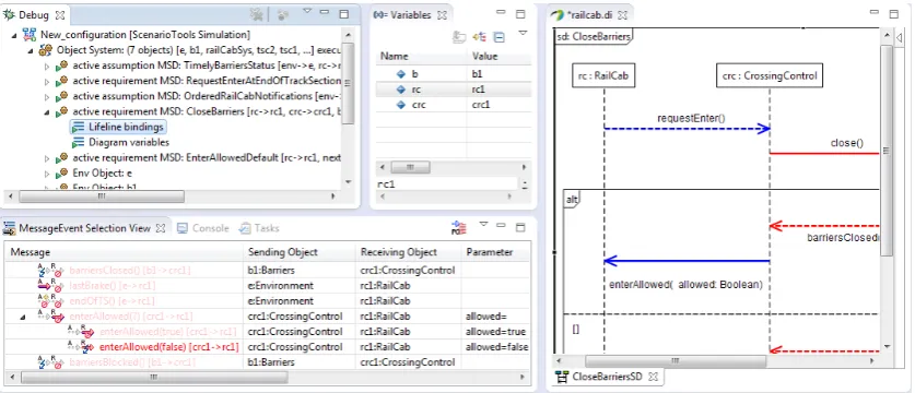
Figure 6: A Screenshot of the simulation in SCENARIOTOOLS
Figure6shows a screenshot of the simulation’s user interface in the SCENARIOTOOLS
SCENARIOTOOLSsimulation for the specification of our RailCab example. It lists the currently active assumption and requirement MSDs. For each active MSD, it displays the current lifeline
bindings in the form[lifeline->object]. It also shows the current position of the cut on
each lifeline in the formlifeline:index (not visible in this screenshot). After the active
MSDs, the list displays all objects in the simulation.
On the bottom left, the MessageEvent Selection View shows the currently enabled,
violat-ing, or initializing message events. In the shown situation, all message events except
enter-Allowed(false) are safety violating in the requirements and therefore “greyed-out”. The
icons on the left of the message name visualize the flags introduced in Section 4for
assump-tions and requirements, respectively. Note thatenterAllowedis only non-violating for the
parametertrue, whilefalseleads to a safety violation. For parametrized messages, all message
events referring to same operation and with the same sending and receiving object, but different parameter values are grouped together.
On the right, the UML editor Papyrus shows an MSD. SCENARIOTOOLSextends Papyrus by
a plug-in to correctly display temperature (red/blue color) and execution kind (dashed or soil arrow) of messages.
6
Related Work
The PLAYENGINE[HM03] and PLAYGOtool [Pla] support the play-out of LSC specifications,
very similar to SCENARIOTOOLS. In the PLAYGO tool, the play-out is based on a
compila-tion of LSCs to AspectJ [MH06], different from the direct interpretacompila-tion of the UML models
in SCENARIOTOOLS. PLAYGO is also Eclipse-based and also supports rich LSC constructs.
However, to the best of our knowledge, SCENARIOTOOLSpresents the first tool to extend the
play-out to also regard environment assumptions. A more in-depth comparison of the tools would be interesting, but exceeds the scope of this paper.
Brill et al. [BBD+04] were the first to mention the use of LSCs to also describe environment
assumptions. They, however, did not consider the execution of LSCs, but only their use for verification.
The second-listed author introduced assumption MSDs and described an automated approach for consistency-checking MSD specifications with assumption MSDs [Gre11]. Within this work, however, no extension of the play-out algorithm was elaborated.
Maoz and Sa’ar recently proposed an approach for incorporating environment assumptions within the LSCs [MS12]. In contrast to our approach, they do not introduce a special kind of LSC. Instead, they interpret hot environment messages as messages that the environment will send. This “inline” formulation of environment assumptions can be easier in some cases. However, in our experience, it is more useful to consider environment assumptions explicitly and independently of the requirements. This way, the assumptions can be validated separately and there is less danger to specify over-optimistic environment assumptions.
In their work, Maoz and Sa’ar elaborated a technique for synthesizing controllers from the extended LSCs. Code can be generated from a resulting controller that can be executed in the
PLAYGO tool. However, a direct play-out of the specification is not supported. Due to
assumptions and other, richer language features, especially dynamic lifelines, is not supported.
7
Conclusion
This paper presents an extension of the play-out algorithm for MSDs with environment
assump-tions that can be specified in the form ofassumption MSDs. These allow engineers to specify
mandatory and forbidden behavior of the system’s environment. As our example illustrates, the ability to model environment assumptions explicitly is crucial because often a system can only satisfy its requirements if the environment does not behave in an arbitrary way.
To the best of our knowledge, we are the first to extend play-out to consider environment assumptions. We implemented the concepts in a novel Eclipse-based tool and evaluated them
using several example specifications (available on our website2). The extended algorithm and
the user interface of SCENARIOTOOLSdisplay detailed information about the effect of different message events. This supports the engineers in making informed choices about the next step.
For future work, we plan further extensions of the MSD formalism and the play-out. For example, we observed that there are two different kinds of environment event: such that can occur spontaneously and such that only occur in reaction to certain steps of the system. Specifying this explicitly could in many cases simplify the specification of the environment assumptions.
Acknowledgements: This research is partially funded by the European Commission, Pro-gramme IDEAS-ERC, Project 227977 SMScom. Christian Brenner is supported by the Inter-national Graduate School “Dynamic Intelligent Systems”.
References
[BBD+04] M. Brill, R. Buschermöhle, W. Damm, J. Klose, B. Westphal, H. Wittke. Formal
Verification of LSCs in the Development Process. In Ehrig et al. (eds.),
Integra-tion of Software SpecificaIntegra-tion Techniques for ApplicaIntegra-tions in Engineering, Prior-ity Program SoftSpez of the German Research Foundation (DFG), Final Report. LNCS 3147, pp. 494–516. Springer, 2004.
[DH01] W. Damm, D. Harel. LSCs: Breathing Life into Message Sequence Charts. InFormal
Methods in System Design. Volume 19, pp. 45–80. Kluwer Academic, 2001.
[Gre11] J. Greenyer.Scenario-based Design of Mechatronic Systems. PhD thesis, University
of Paderborn, October 2011.
[HM02] D. Harel, R. Marelly. Specifying and Executing Behavioral Requirements: The
Play-In/Play-Out Approach.Software and System Modeling (SoSyM)2:2003, 2002.
[HM03] D. Harel, R. Marelly.Come, Let’s Play: Scenario-Based Programming Using LSCs
and the Play-Engine. Springer, August 2003.
[HM08] D. Harel, S. Maoz. Assert and negate revisited: Modal semantics for UML sequence
diagrams.Software and Systems Modeling (SoSyM)7(2):237–252, May 2008.
[Mao09] S. Maoz. Polymorphic Scenario-Based Specification Models: Semantics and
Appli-cations. In Schürr and Selic (eds.),Proc. 12th Int. Conf. on Model Driven
Engineer-ing Languages and Systems, MODELS 2009, Denver, CO, USA, October 4-9, 2009.
LNCS 5795, pp. 499–513. Springer, 2009.
[MH06] S. Maoz, D. Harel. From Multi-Modal Scenarios to Code: Compiling LSCs into
AspectJ. In Proc. 14th Int. Symp. on Foundations of Software Engineering.
SIG-SOFT ’06/FSE-14, pp. 219–230. ACM, New York, NY, USA, 2006.
[MHK02] R. Marelly, D. Harel, H. Kugler. Multiple Instances and Symbolic Variables in
Ex-ecutable Sequence Charts. In Proc. 17th Conf. on Object-Oriented Programming,
Systems, Languages, and Applications (OOPSLA ’02). ACM SIGPLAN Notices 37, pp. 83–100. November 2002.
[MS12] S. Maoz, Y. Sa’ar. Assume-Guarantee Scenarios: Semantics and Synthesis. In
France et al. (eds.),Model Driven Engineering Languages and Systems. LNCS 7590,
pp. 335–351. Springer Berlin Heidelberg, 2012.
[Pla] PlayGo Tool. last accessed Dec. 2012.